






Abstract
A unified formulation that accounts for the dynamics of a general class of aquatic multi-body, soft-structured robots is presented. The formulation is based on a Cosserat formalism where the description of the ensemble of geometrical entities, such as shells and beams, gives rise to a multi-soft-body system capable of simulating both manipulation and locomotion. Conceived as an advanced tool for a priori hardware development, n-degree-of-freedom dynamics analysis and control design of underwater, soft, multi-body, vehicles, the model is validated against aquatic locomotion experiments of an octopus-inspired soft unmanned underwater robot. Upon validation, the general applicability of the model is demonstrated by predicting the self-propulsion dynamics of a diverse range of new viable combinations of multi-soft-body aquatic system.
1. Introduction
Fostered by the growing needs of the marine and maritime industry to perform increasingly daunting tasks in always more forbidding environments, a renovated effort is being made nowadays to endow underwater robots with enhanced manoeuvring capabilities. On the one hand this has entailed the revision of traditional systems (Elvander and Hawkes, 2012; Vaganay et al., 2009; Vasilescu et al., 2010), or by improving navigation and positioning systems, i.e. by combining data collected jointly from doppler velocity logger (DVL), GPS, pressure-depth sensors, synthetic aperture sonars, and multi-beam echo sounders (Hover et al., 2012). On the other hand, alternative design criteria have been taken in consideration by capitalizing on the study of water-dwelling organisms.
In recent times underwater robotics has largely benefited from the growing fascination for bioinspired aquatic locomotion and, motivated by the abundance of outstanding feats that aquatic animals display, has started to pave the way for the development of new vehicles capable of feats yet to be seen in commercially available unmanned underwater vehicles (UUVs). Hovering, short radius turning, fast start/slowdown, and low-speed manoeuvring are just few examples that highlight how the design of underwater robots can profit massively from the investigation of the swimming strategies, hydrodynamics, and physiology of aquatic animals.
Several examples exist of aquatic organisms which have been taken as the source of inspiration for designing a trustworthy robotic replica. These include flagellates (Abbott et al., 2009), turtles (Licht et al., 2004), eels (Yu et al., 2012), and, of course, fish. The finned and caudal flapping of fish (e.g. Conte et al., 2010; Saimek and Li, 2001), has gathered the most recognition in the scientific community, in part because of the sound understanding of the underlying physics involved in their locomotion (Colgate and Lynch, 2004).
The locomotion of aquatic organisms and their robotics counterparts commonly involves periodic oscillatory deformations of one or more body parts that, in turn, give rise to the unsteady hydrodynamics responsible for generating thrust. The actuation mechanisms that enable these deformations in the bioinspired water-dwelling robots has, in most cases, entailed the replacement of continuously deforming bodies by reducing the number of degrees of freedom (DOFs) with a finite sequence of rigid links and joints. Alternatively, the compliant nature and the multi-DOF bending capability of the biological counterpart has been accounted for by resorting to continuously deforming soft structures and actuators (Marchese et al., 2014). The effort in designing structurally compliant underwater robots is fostered, to a large extent, by the acknowledgement that safe physical human–robot interaction and manoeuvring in highly perturbed, unstructured scenarios can effectively be handled via the recourse to soft-bodied components rather than by making the control finer (Mortl et al., 2012; Wang and Iida, 2015; Woodman et al., 2012). Indeed, commercial underwater robots are safe traveling in open stretches of sea, but suffer from non-negligible limitations when navigating close to the seabed or in close proximity to submerged structures where unintended impacts must be prevented consistently. The exploitation of soft-bodied vehicles that benefit of the assets from bioinspired propulsion and manipulation systems can provide a viable solution to complex tasks that existing remotely operated underwater vehicles (ROVs) and autonomous underwater vehicles (AUVs) are unfit for such as operations in current-perturbed domains, performing maintenance over the hull of ships and harbors and working in synergy with divers.
This has encouraged the authors to design and develop an innovative class of soft-bodied, bioinspired, underwater robots (Figure 1). These consist of octopus-resembling machines endowed with a number of continuous manipulators (element 4 in Figure 2), and a central unit devoted to thrust generation (element 1 in Figure 2), which essentially defines an underwater multi-limbed soft vehicle (Giorgio-Serchi et al., 2017). The robot is composed by as much as 90% in volume by elastomeric materials and actuation is provided by electric motors and cable transmission thus enabling the robot to profit from a high overall degree of structural compliance. In analogy with its biological source of inspiration, this kind of robot is capable of performing basic manipulation, legged locomotion, and waterborne propulsion. On one_ hand, this kind of design offers a number of assets due to its structure and mode of actuation that have been covered at length by Giorgio-Serchi et al. (2016, 2015), as far as propulsion is concerned, and by Renda et al. (2014) for manipulation. On the other hand, however, the morphology of the robot also requires an ad hoc formulation in order to treat the dynamics of this flexible multi-body system. This represent the focus of the present work. The mechanical system of Figure 1, with its articulated configuration and its combination of flexible and rigid components represents the state-of-the-art paradigm for developing and validating an advanced mathematical framework capable of dealing with such complexity.
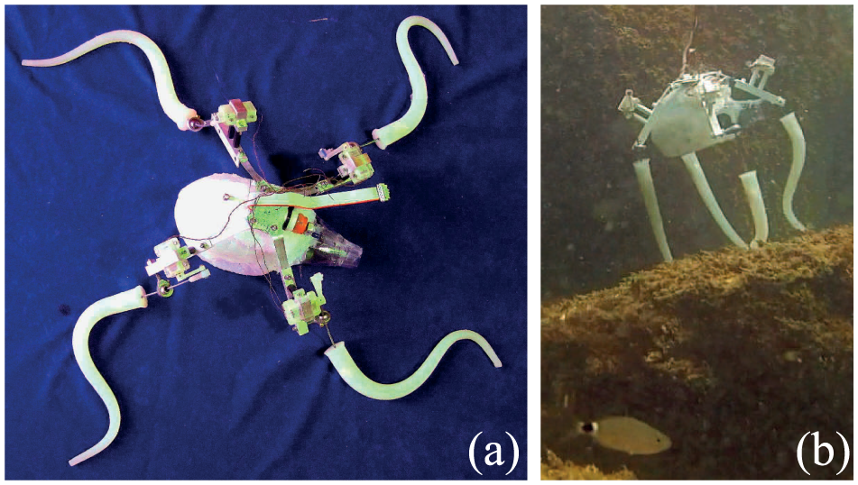
(a) The soft, multi-body aquatic robot developed by the authors. (b) During testing at sea.
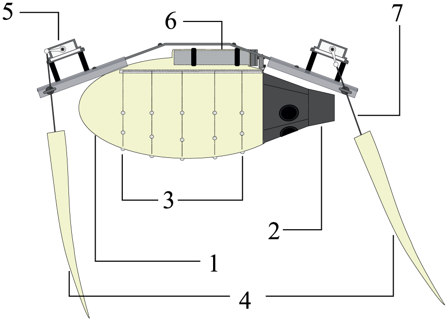
A schematic of the soft, multi-body aquatic vehicle developed by the authors. Numbers refer to: (1) pulsed-jet thruster; (2) the nozzle; (3) the cables that drive the shell collapse; (4) the continuum manipulators; (5) the actuators of the manipulators; (6) the actuator of the shell; and (7) the cable that drives manipulator actuation.
With the advancement in bioinspired robots, increasingly sophisticated mathematical models have been developed with the scope of accounting for the growing complexity of such systems (Krieg et al., 2015). As far as aquatic robots are concerned, the swimming routine commonly entails caudal or finned flapping and whole-body undulatory oscillations. An extensive literature exists that accounts for the dynamics entailed with these kinds of swimming routines, as well as with the associated accurate flow features. Whereas a rigorous treatment of these kinds of systems requires the solution of a full hydroelastic problem, physically sound and less numerically intensive approaches have been found to be well suited for the purpose of control and design optimization. These have entailed the reduction of the problem to a coupling between the body, regarded either as a series of rigid links or as continuously deforming beams, and the fluid as a quasi-inviscid one, where reactive inertial terms are computed via potential flow theory and resistive viscous terms are derived from empirically determined coefficients.
This approach has been applied in recent years to the swimming of fish via an extended Lighthill model that expands the large-amplitude elongated body theory (LAEBT) of (Lighthill, 1970) to the case of self-propelled three-dimensional swimming (Boyer et al., 2010). This latter formulation has been employed to encompass the case of non-quiescent ambient flows, such as in the Von Karman vortex street from which a dead fish is shown to extract energy in order to passively propel itself upstream (Candelier et al., 2013). This model accounts for most of fish morphologies (anguilliform, carangiform) by treating the fish body as a nonlinear Cosserat beam in finite transformations (deformations and rotations), i.e. an infinite set of rigid cross-sections (thus modeling, in a way, the fish vertebrae) regarded as continuously stacked along the vertebral axis of the animal. It can be shown (Candelier et al., 2011), by exploiting the tapered shape of the body, that the fluid forces exerted on a beam cross-section only depend on the fluid velocities and acceleration of the water slice that prolongs the beam cross-section in the fish surrounding. Based on this remark, it becomes possible to extend the Newton–Euler-based approach of rigid discrete multi-body systems dynamics to the case of continuous systems where the cross-sections label stand for the body index of the discrete case. In this context, the inverse (computed torque) algorithm of Luh et al. (1980) has been extended to the locomotion of continuous elongated systems in Boyer et al. (2006). Remarkably, the resulting dynamics approach exploits the topology of these continuous systems to design fast dynamics algorithms where the usual recursions of the Newton–Euler algorithms are replaced by ordinary differential equations (o.d.e.s) that are solved forward and/or backward along the beams axisin a global time loop. Furthermore, compared with other approaches, such as those based on the floating frame (Canavin and Likins, 1977), they can naturally tackle the finite deformations observed in soft animals, an advantage that is crucial in the context of this article.
Whereas modern modeling paradigms essentially pertain to the multi-body or continuous approach, the need arises to reconcile these supposedly divergent perspectives into a more general view capable of encompassing both counterparts. In the present work, of which a preliminary version has been presented in Renda et al. (2018), the dichotomy between the multi-rigid-body and the single-continuous-body paradigms is relaxed by expressing the whole-body dynamics of an octopus-like robot via a multi-soft-body formulation. To do so, we expand on the state-of-the-art geometrical models of archetypal elements, such as beams and shells, to construct a unified framework where various appendages are allowed to participate to the dynamics of a single entity. As a mean of validating this construct, the model is employed to replicate the robot depicted in Figures 1 and 2 and compare the simulated with the experimentally observed dynamics during aquatic self-propulsion. The versatility of the mathematical framework introduced is demonstrated by extending it to account for a set of diverse geometrical configurations and actuation routines.
The first section of this paper entails an extended general description of the mathematical frames exploited throughout. In Section 3 this is employed to illustrate the modeling formalism adopted for beams and shell-shaped soft bodies, which are later considered in a unified system (Section 5). The model thus formulated is then validated for the case of a four-limbed, self-propelling, soft robot closely resembling one of the vehicles developed previously by the authors (Section 6). Eventually, in Section 7 we demonstrated how this unified model for multi-soft-body vehicles can be exploited with the purpose of exploring innovative design paradigms by predicting the locomotion performances of two distinct soft underwater vehicles.
2. Model description
The basic structure of the model is made by a rigid body, called rigid root-body, and several soft appendages attached to it through one extreme or boundary of the soft body (beams and axisymmetric shells in this work). The rigid root-body is not kinematically attached to any hard frame, but instead it is free to move in the 3D space, whereas the soft appendages are not connected to each other preventing the realization of closed-loop mechanisms. This kind of multi-body system is said to have a star structure (Selig, 2007).
Let us call
Each of the soft appendages are modeled as Cosserat medium, which can be intuitively considered as a continuous staking of a rigid small solid named “microstructure” along one (beam) or two (shell) material dimensions. As a result, the configuration space of such a medium can be intrinsically defined as the set of maps (Figure 3):

where g is a field of rigid transformations mapping the inertial frame onto the frames attached to each of the microstructures that constitute the medium. This definition holds for beams (p=1) and shells (p=2).
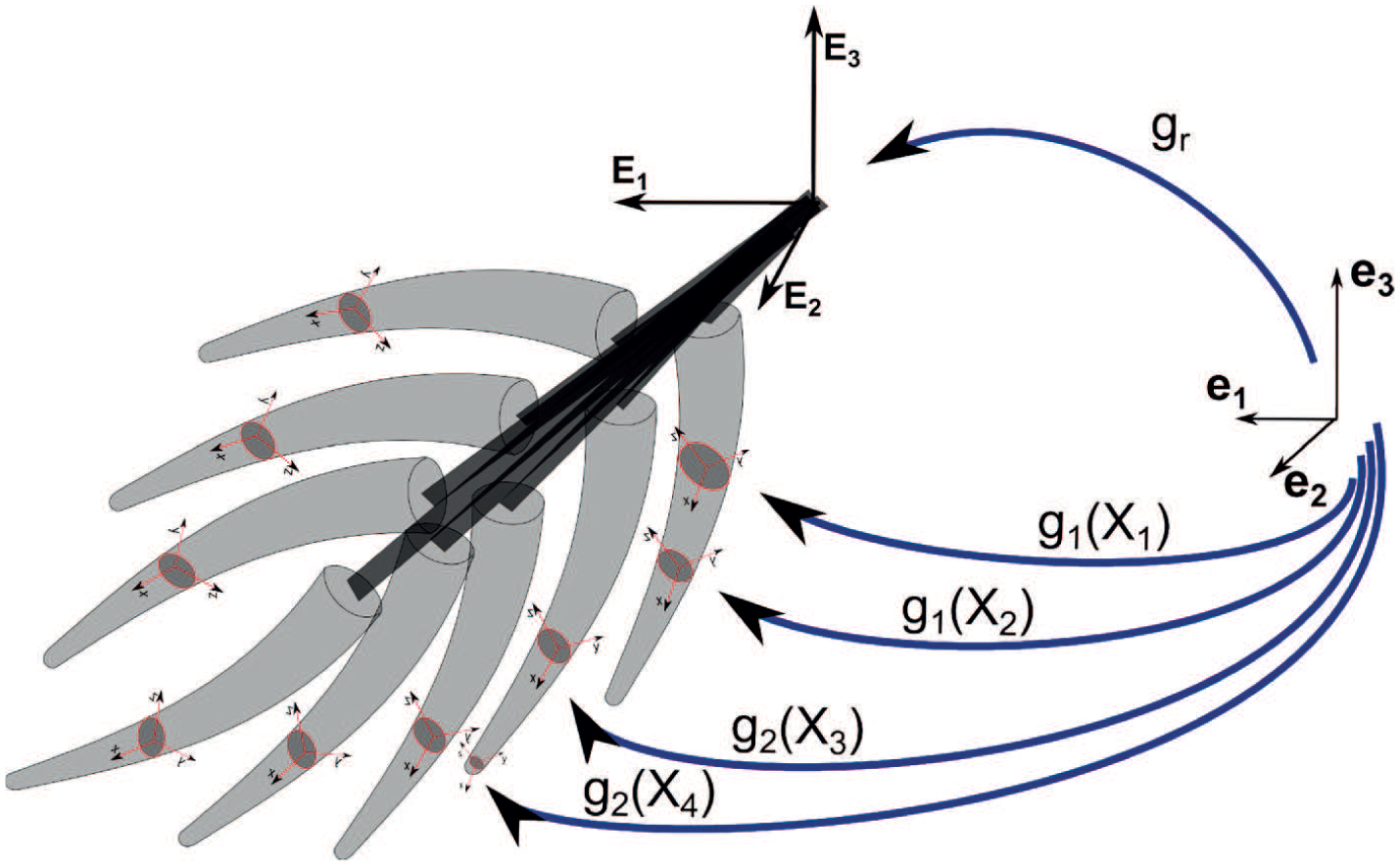
Schematic description of the general configuration of a multi-soft-body system.
2.1. Multi-soft-body configuration space
In our definition of the configuration space of the multi-soft-body system, the net motion is separated from the deformation of the soft subsystems and the configuration space of the system is defined as
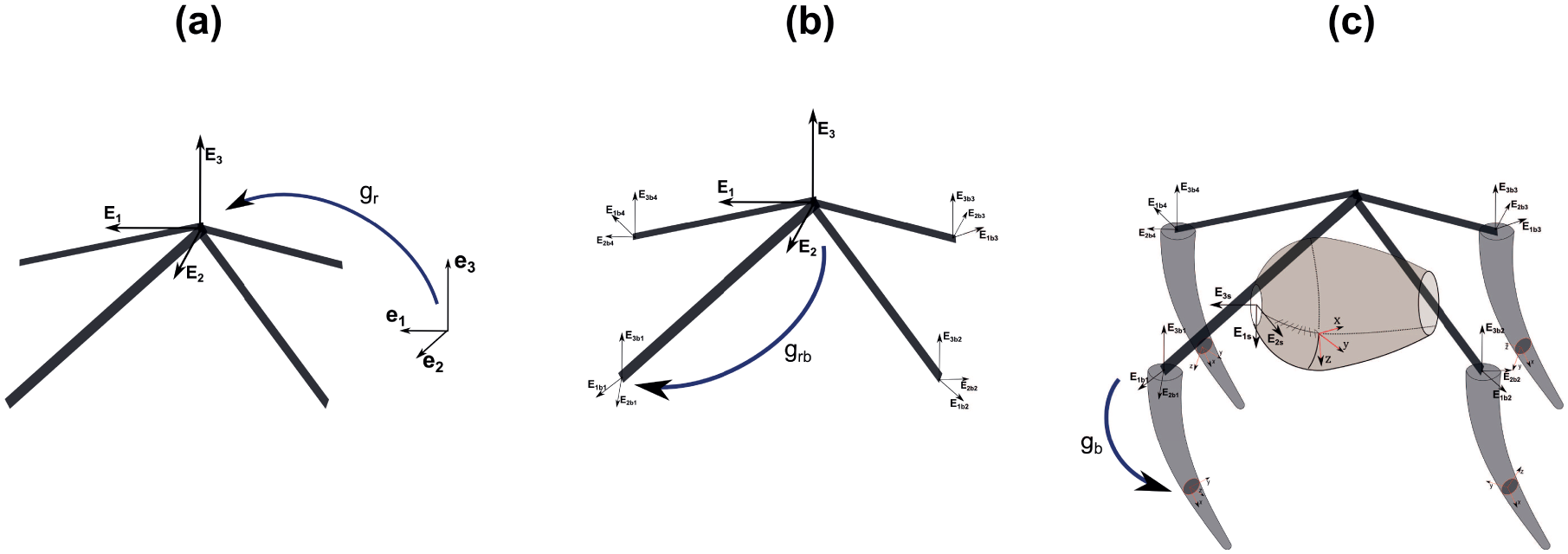
Schematic description of the multi-soft-body configuration and the map’s hierarchy between the frames used in the model.
It is worth noting that the configuration spaces of the constitutive bodies (soft or rigid) sharing as common structure the Lie group SE(3), their dynamic models can be encompassed in a common framework that is presented in the subsequent developments.
3. Cosserat model for soft robotics
In this section, a brief description, based on the authors previous works (Renda et al., 2014, 2015c), of the kinematics and dynamics of soft robot arms (SRAs) and soft shell mantles (SSMs) for underwater soft robotics is given.
3.1. Kinematics
In the Cosserat theory, according to Equation (1), the configuration of a micro-solid of a soft body with respect to the inertial frame at a certain time is characterized by a position vector u and a material orientation matrix R, parameterized by the material abscissas, that are

As described in the previous section, the map g is the composition of three transformations,
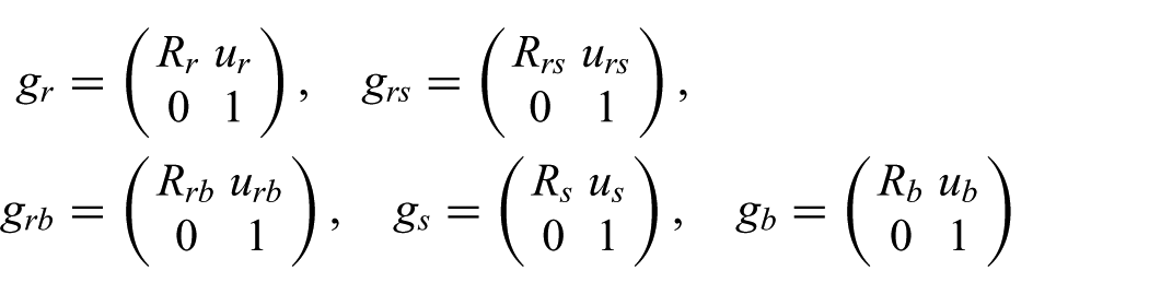
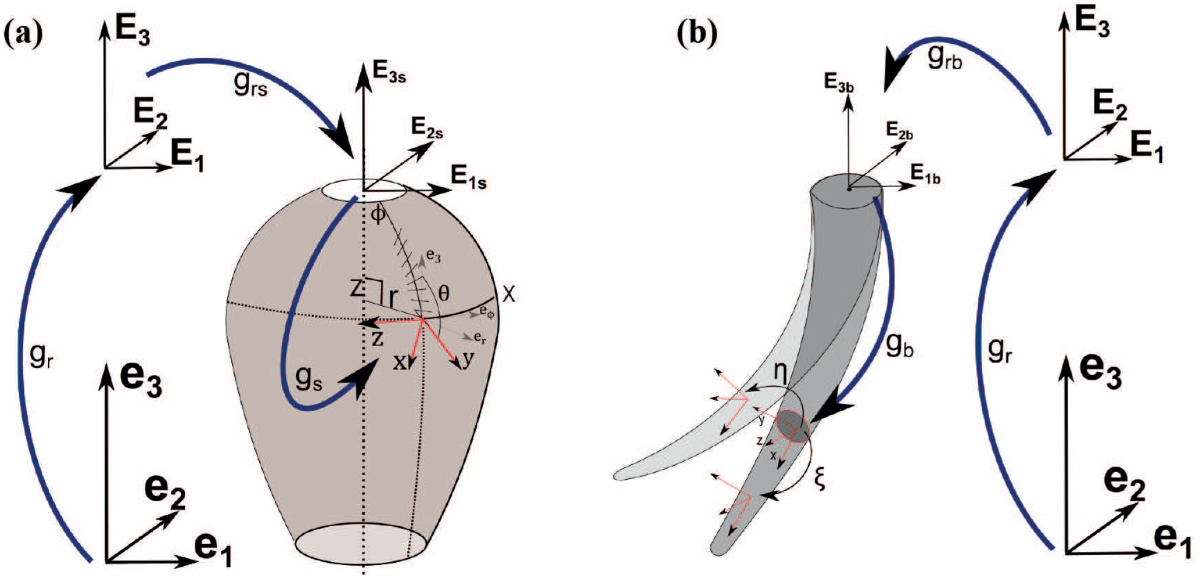
Sketch of the kinematics which show the geometrical meaning of the elements g,
Furthermore, exploiting the axisymmetry of the shell, the transformation
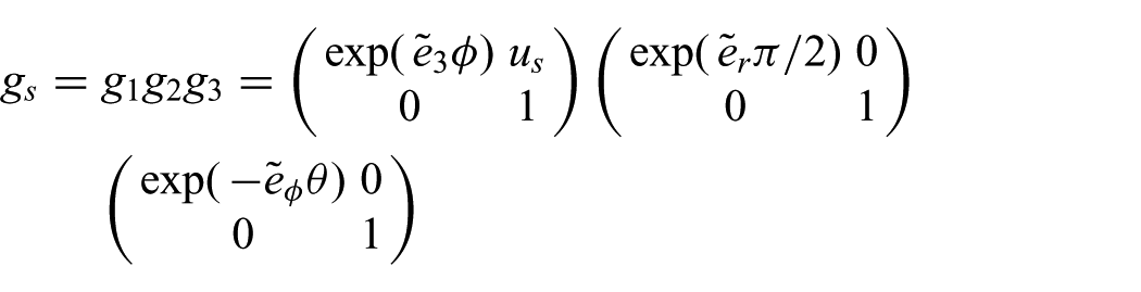
where
Based on these kinematics, the strain state of the beam is defined by the vector field along the curve
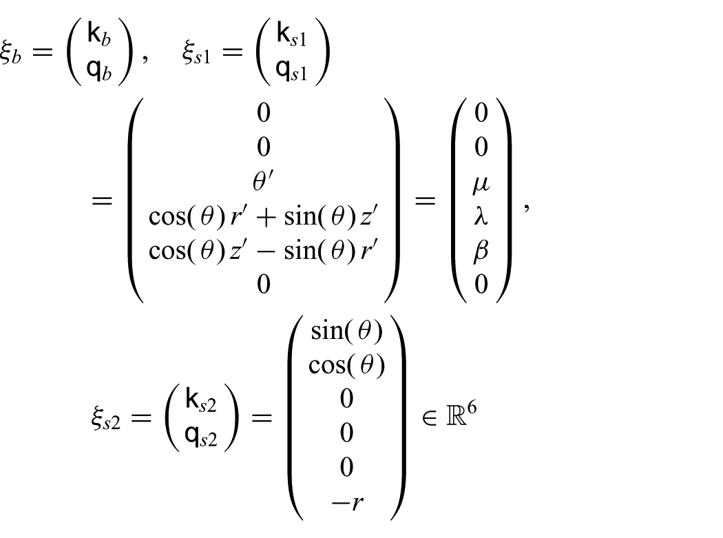
where
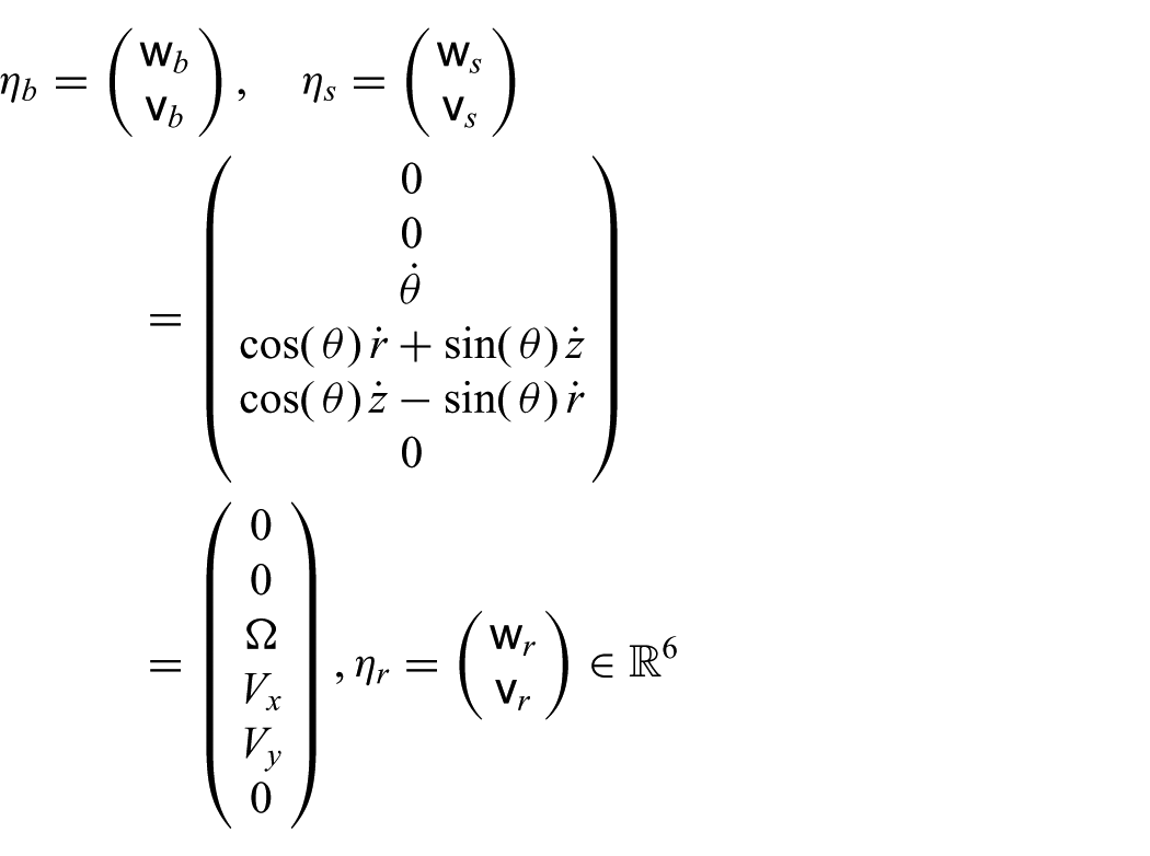
where

3.1.1. Strain measures
There are different ways to measure the strain of a continuous media, we choose the most commonly used in the specialized literature for the beam (Simo, 1985) and shell (Simo and Fox, 1989), respectively.
For the SRA, the strains are defined as the difference between the X -rate of g in the deformed configuration
For the SSM, in accordance with Simo and Fox (1989) as described in Renda et al. (2015c), the strain tensor field which describes the membrane strain state in the mid-surface is
3.2. Compatibility equations
We have seen above that

Then, we can simplify these equations by noting that


which remarkably depend only on the “shape” component of the multi-soft-body configuration space.
3.3. Dynamics
The partial differential equations (p.d.e.s) describing the evolution of a Cosserat rod and shell (not necessarily axisymmetric) have been derived by Reissner (1990) and exploited in Simo (1985) and (Simo and Fox, 1989), respectively, for nonlinear finite element analysis. More recently, they have been used in the context of continuous and soft robotics in Boyer et al. (2006) Candelier et al. (2013), Renda et al. (2014), and Renda et al. (2015c). Boyer and Primault (2005); Boyer and Renda (2016) showed that these beam (respectively, shell) p.d.e.s, together with their boundary conditions, can be derived directly from an extension of a variational calculus on Lie groups historically introduced by Poincaré (1901):
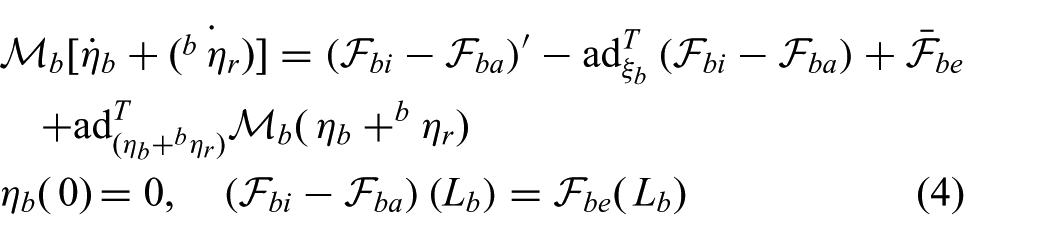
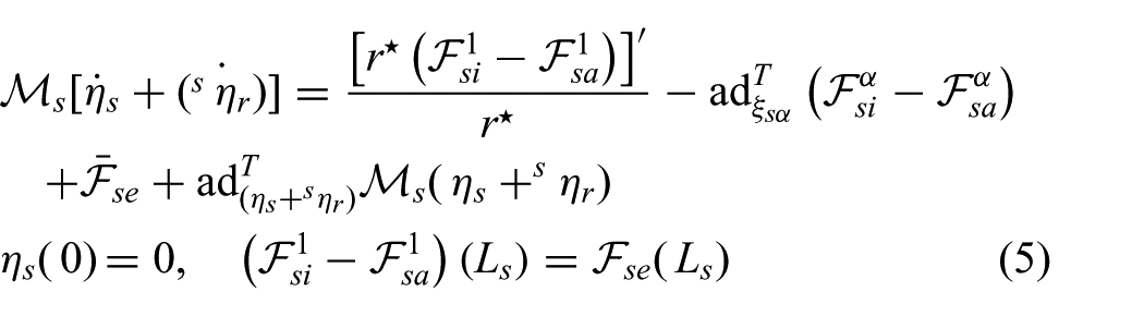
where
Let us specify the angular and linear components of the internal and external wrenches (for the axisymmetric shell refer to Renda et al. (2015c) and Antman (2006)):
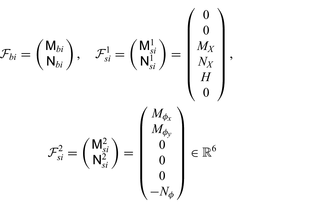
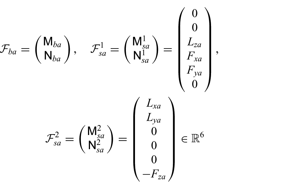
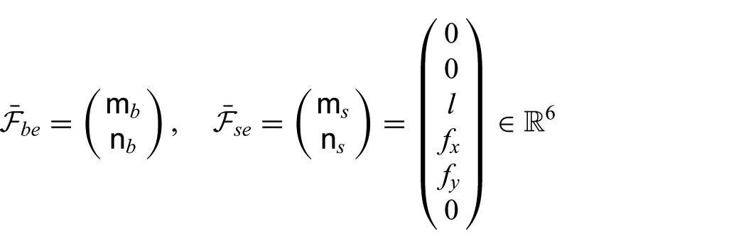
where
As for the compatibility equations, we have
The imposed internal actuation wrenches (
3.4. Constitutive equations
A linear viscoelastic constitutive equation, based on the Kelvin Voigt model, is chosen. Following Linn et al. (2013) for the SRA and Simo and Fox (1989) for the SSM we respectively obtain

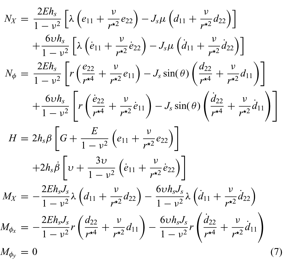
where
3.5. External loads
The external loads taken into account are those exerted by the fluid (i.e. drag, added mass, buoyancy, and thrust) in addition to the gravity load. Mathematically, we have


where
An exhaustive derivation and interpretation of the fluid force model for the SSM has been presented in Renda et al. (2015b), based on the usual model of net external forces exerted on a rigid rocket, uniformly distributed overthe mantle. In this formulation, certain terms which participate in the definition of the total propulsive thrust are neglected. These concern, in particular, the internal pressure contribution associated with the dynamics of the cavity collapse, referred to by Krieg and Mohseni (2015) as total jetting force (see also Anderson and DeMont (2000)), as well as the positive feedback from the added mass variation of the collapsible shell (Giorgio-Serchi and Weymouth, 2016a,b). Here only the final equation is reported, whereas the SSM gravity and buoyancy loads are accounted for together with the rigid root-body so that the shell symmetry is not broken. For the SRA, the fluid force models have been originally derived in Boyer et al. (2006) and then introduced in a soft robotics context in Renda et al. (2014).
Gravity and buoyancy are simply the product between the mass per unit of

where G is the gravity acceleration vector, equal to
The drag load vector is proportional to the square of the velocity vector and is directed in the opposite direction. The amplitude of the drag load is also determined by the geometry of section


where
The added mass load vector is proportional to the acceleration vector and is directed in the opposite direction. The amplitude is also determined by the geometry of section
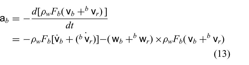
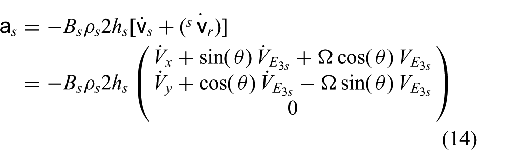
where
The thrust load is

where
4. Rigid root-body model
We here seek the dynamic model of the system net motions controlled by the shape deformations of the soft subsystems (Boyer and Porez, 2015). To do that, the kinematics and dynamics of the rigid root-body that connects the soft bodies in a star system are presented, together with the reaction wrenches due the soft appendages. This leaves to the following equation:

where

which plays the role of a reconstruction equation. For our soft unmanned underwater vehicle (SUUV), the rigid root-body is composed by four rectangular parallelepiped bars in a pyramidal configuration (Figure 6), hence, the inertia matrix takes the form

where
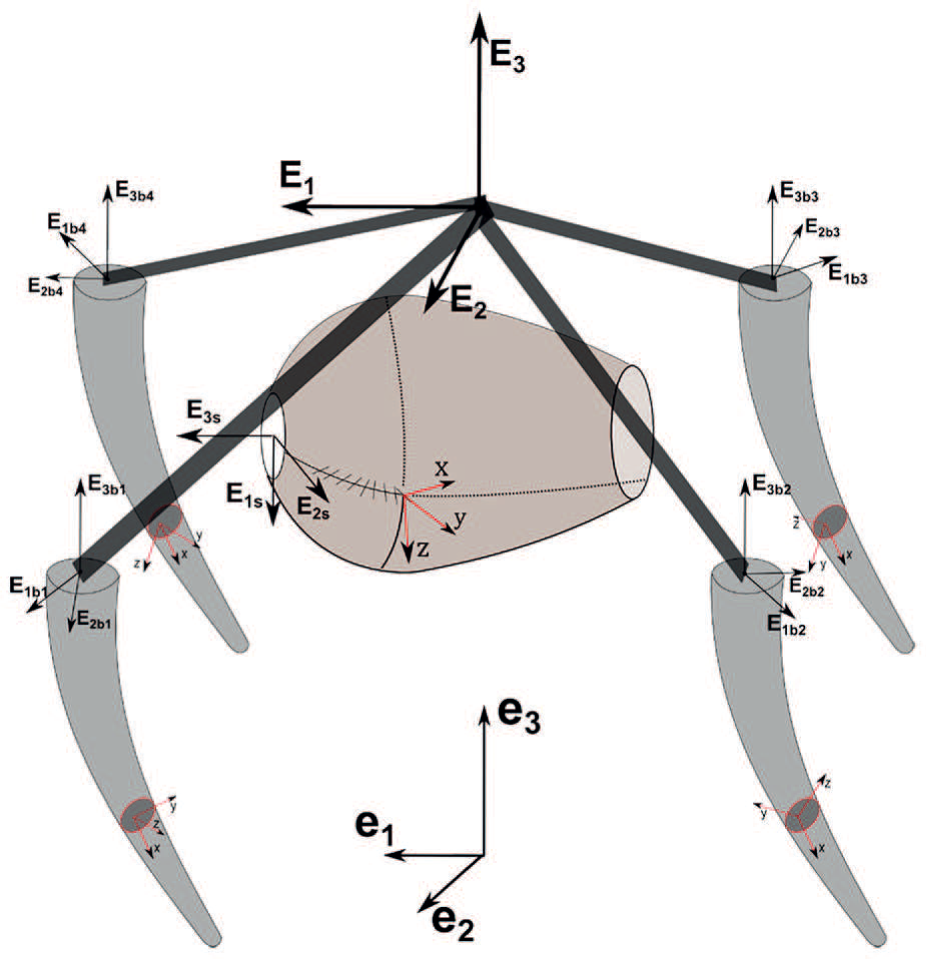
illustrative scheme of the soft unmanned underwater vehicle (SUUV) kinematics, where
4.1. Root-body external loads
The external loads comes from the interaction of the rigid root-body with the environment. In our case, they are equal to

where
Similarly to Section 3.5, for the external loads we have



where
4.2. Root-body reaction loads
For what concern the reaction loads due to the attached soft appendages (
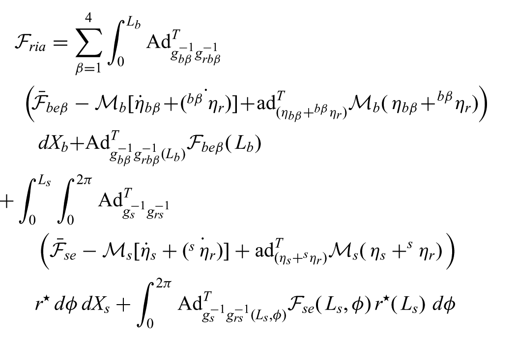
where
Making use of the dynamic equations (4) and (5) (and their boundary condition), the right-hand side of the equation above can be derived by integrating the internal and actuation loads of the soft bodies leading to
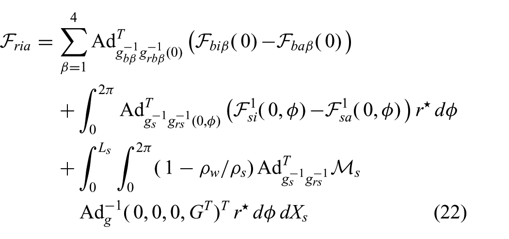
where the neglected gravity and buoyancy loads of the SSM have been recovered.
5. Multi-soft-body dynamic model
In Section 3, the kinematics, compatibility, and dynamic equations for two type of soft bodies, i.e. the SRA and the SSM, have been given, whereas in Section 4, the rigid root-body kinematics and dynamics governed by the reaction wrenches of the soft appendage have been developed. Finally, here we are able to present the multi-soft-body system model and outline the solution algorithm that leads to the complete motion of the underwater soft vehicle.
5.1. Star system dynamic model
The final system of equations is composed by the o.d.e.s of the root-body and the second-order p.d.e.s of the soft bodies. The system of o.d.e.s for the root-body is composed by the kinematic equation (17) and the dynamic equation (16), endowed with the reaction load (22) and external loads (19), (20), and (21). The system of p.d.e.s for the SSM and the SRA is composed by the kinematics equation presented in Section 3.1, the compatibility equations (3) and (2), and the dynamic equations (5) and (4), in turn complemented with the internal elastic stresses (7), (6) and the external loads (10), (11), (12), (13), (14), and (15). Finally, in the state form
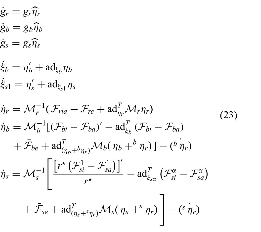
In Figure7 a diagram of the time integration loop is shown. The input of the model, directly function of time, are the actuation loads
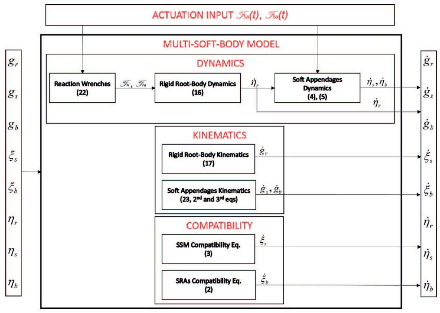
Diagram of the time integration loop algorithm. On the left, the current status of the state variables is plug into the multi-soft-body model where
The algorithm has been implemented in MATLAB®. The numerical scheme used is a decentralized (for the SRA) and centralized (for the SSM) space differentiation finite difference method, based on a fourth-order Runge–Kutta time integration with variable time step (by means of the MATLAB® ode45 function) (Renda et al., 2014, 2015b). A spatial distribution of one material point for every 5 mm (for SRA) and 1 mm (for the SSM) was adopted. Our implementation of the MATLAB® code is available on GitHub (github.com/federicorenda/Unified-Multi-soft-body-Dynamics) under the permissive BSD 3-clause license.
6. Experimental results
Having defined the modeling framework valid for an arbitrary multi-soft-body system, it is necessary to assess the degree of accuracy of such formulation with respect to experimental data. With this purpose in mind, the data collected from experimental trials of the vehicle depicted in Figures 1 and 2 are employed. Upon assessment of the degree of accuracy of the formulation presented, the model can be employed for innovative design exploration, as later demonstrated in Section 7, design optimization and control purposes.
Tests on the vehicle were performed in a controlled environment to provide the basis for model verification. The tests entailed the robot moving along a straight track inside a working space with the shape of a rectangular box delimited by eight markers, see Figure 8. By making use of two cameras and three additional markers (see element [2] in Figure 8) fitted on the central part of the robot, a three-dimensional reconstruction of the body position and orientations is derived via direct linear transformation.
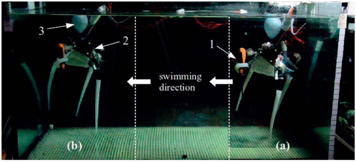
Two screenshots from the digital camera recordings taken during robot testing at (a) the start and (b) end point of the experiment. The robot is portrayed with an arm twirled around a screwdriver [1]; the variable buoyancy module [3] and the LED markers for 3D tracking [2] are visible.
The experiments were performed in a 1150 mm long, 590 mm wide, and 500 mm deep tank filled with fresh water. The tests consist in recording the displacement of the body as it propels itself from one end of the tank to the other. Recordings are performed with a digital camera at 25 fps and later processed with an image tracking software and a Savitzky–Golay low-pass filter eventually yielding the displacement and velocity in the surge direction.
The robot is allowed to travel along a straight line inside the tank by letting the motor revolve at a quasi-constant angular velocity. The overall body of the vehicle is slightly negatively buoyant, thus requiring the use of an inflatable buoyancy module (see element [3] in Figure 8) fitted to the dorsal part of the robot to achieve a condition of consistent neutral buoyancy. Tests were repeated at motor angular velocity ranging from 5 to 15 rad/s, i.e. from 0.8 to 2.4 pulsations per second (pps). The vehicle is allowed to translate along the surge direction only, whereas the motor is supplied with a constant voltage. The result of the pulsed-jet mode of propulsion generates a quasi-sinusoidal velocity signal.
In addition, from the recordings of electric current, the tension of the cable bundle at the crank is derived; this is taken as the input force in the elastodynamics model. The electric current supplied to the motor throughout the pulsation cycle was measured in the case of a forcedly stationary prototype. This grants that the dynamic effect of the external flow during vehicle displacement could not affect the load acted upon the shell during actuation. A short section of the recordings of the cable tension pattern during actuation of the prototype is shown in Figure 9.
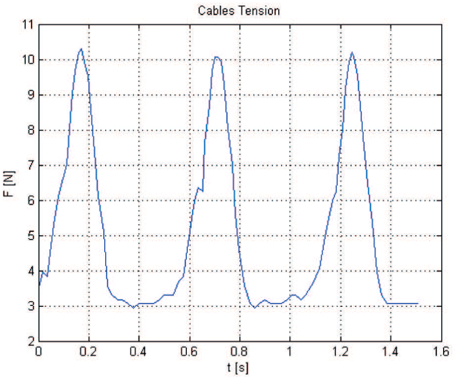
Cables tension of a forcedly not moving prototype with a motor frequency of 2 pps (pulsations per second).
6.1. Underwater locomotion comparison
The separated model for the SRA and the SSM have been experimentally validated in Renda et al. (2014) and Renda et al. (2015b), respectively (see also Renda et al. (2015a) for the SSM in steady-state condition). Taking advantage of this fact, the same mechanical and dynamical parameters obtained there are applied here to the new geometries. The geometry of the SSM has been represented with an half sphere with a radius
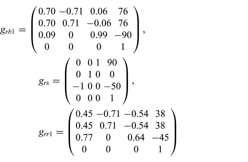
whereas
Parameters of the SRA and the SSM.

Parameters of the rigid root-body for the Poseidron, Quadropus, and Monopus.

To derive a force input for the model, readings from the motor encoder are employed. Given a torque constant of 6.6 mNm/A, a motor maximum efficiency of 79% and a gearhead transmission efficiency of 73%, the estimate of time-varying experimental torque output, and hence model force input, is computed from current data as depicted in Figure 9. The harmonic oscillations depicted in Figure 9 are associated with the stages of inflation and deflation of the elastic shell which result in the periodic pull and release exerted upon the cables, as discussed at length in Giorgio-Serchi et al. (2016). The input of the model is the rhythmic actuation of the SSM provided by the cables. This can be modeled by taking the radial force
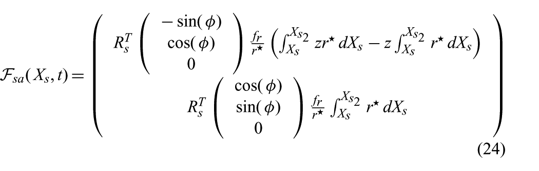
where the lower bound of the integral therein becomes equal to
The results of the comparison for three motor frequencies (1.89, 1.51, and 1.26 pps) are shown in Figure 10. The distance between the two values has been evaluated with respect to the mean swimming velocity
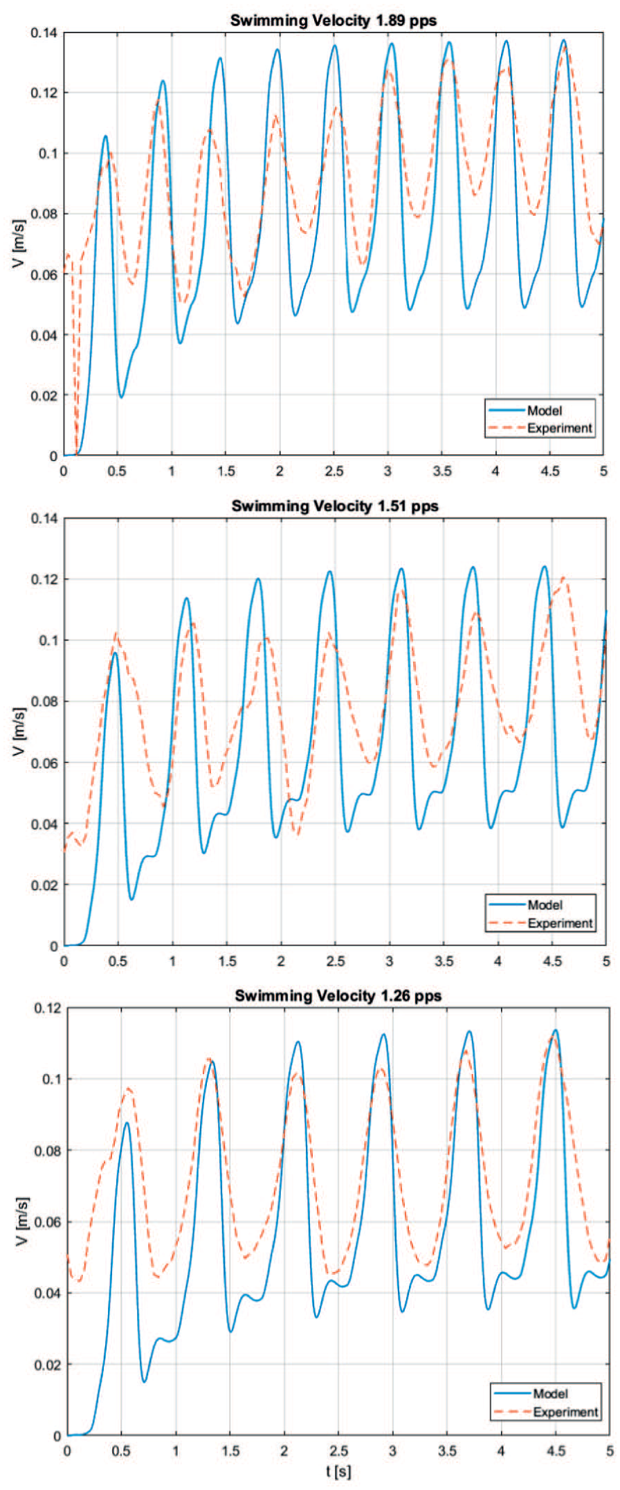
Real and simulated swimming velocity of the soft robot for tests performed at 1.89, 1.51, and 1.26 pps.
At present, the main source of error pertains to the hydrodynamic loads prediction that is largely affected by the difficulty to estimate in closed-form solution the contribution from the time-varying shape variations inside and around the SSM body. Inertial and viscous effect during expulsion and suction of fluid from the cavity do represent prominent terms in the dynamics of the shell. However, given the accuracy of the validation, it is reasonable to expect that, for the range of actuation frequencies investigated, neglecting these terms may represent an acceptable assumption.
7. Exploration of alternative designs
In this section, we explore the capabilities of the model to predict the dynamics of new conceptual prototype which are based on different arrangements of the baseline reference structures. In particular, the behavior of an underwater soft robot, referred to as Quadropus due to its four-limbed structure, with four SRAs stacked at the back of the SSM is analyzed, and the navigation capabilities of a vehicle, called Monopus, with one single SRA used as a steering mechanism are shown. These examples demonstrate the capability of the model to deal with simultaneous actuation of different modules during six-dimensional underwater swimming scenarios. Whereas these analyses are not meant to be conclusive, we aim at demonstrating the flexibility of the present model to treat a broad range of geometrical configurations and actuation routines and how these can be used to infer critical design parameters relevant to robot design such as power consumption and control optimization. Ultimately, this kind of analysis may be of value to study aquatic living organisms to derive an accurate biomechanical characterization of their swimming strategies.
In Figure 11, the new configurations of the soft bodies and the rigid root-body for the Quadropus and the Monopus is illustrated. From a modeling perspective, the description of these new morphological configuration is reflected in the value of the constant transformations
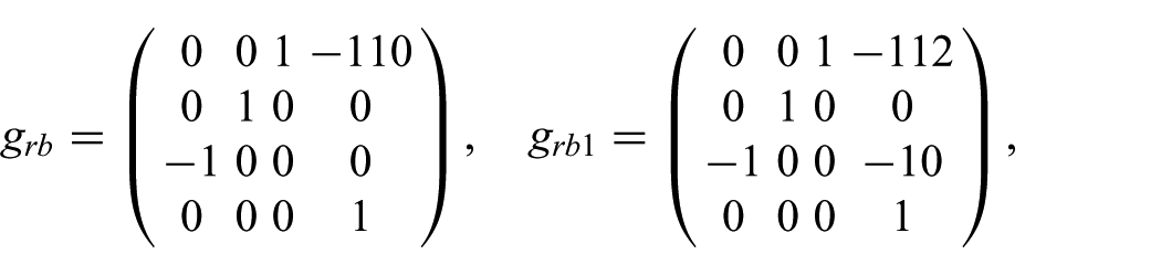
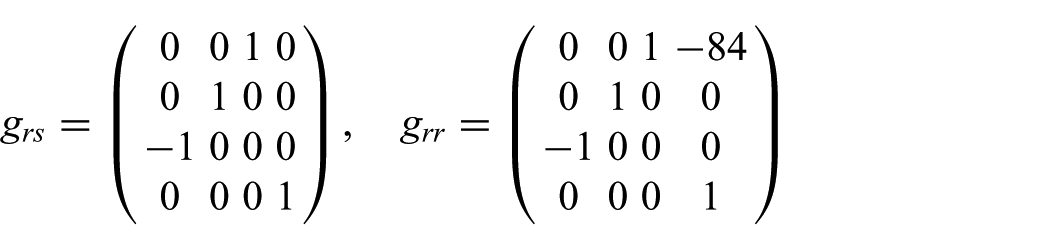
whereas
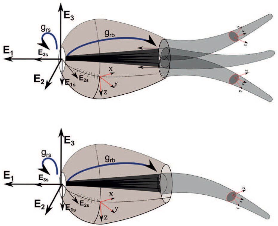
illustrative scheme of the kinematics of the new structures explored. The new structures are obtained simply by modifying the value of the constant transformations
For both of these designs, the parameters that define the SRA and SSM are kept as in the previous section and summarized in Table 1. The rigid root-body, on the other hand, is now a solid cone 112 mm long, with a base radius of 20 mm and the same mass and hydrodynamic coefficients of the prototype root-body (Table 2). Hence, the only variation introduced in terms of parameters lies in the different rotational inertia of the cone geometry with respect to the four-bar system.
7.1. Quadropus dynamics
The Quadropus represents an octopus-like body that is able to exploit the combined effects of pulsed-jetting as well as the sculling of its tentacles. Pulsed-jet activation is implemented as a force acting along the circumference of the shell and given by
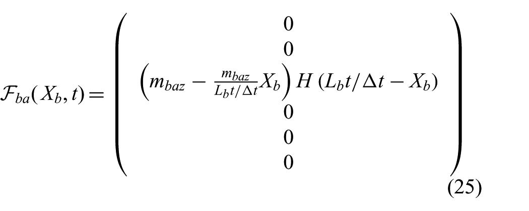
for
The employment of different amount of torque in the actuation of the SRMs for
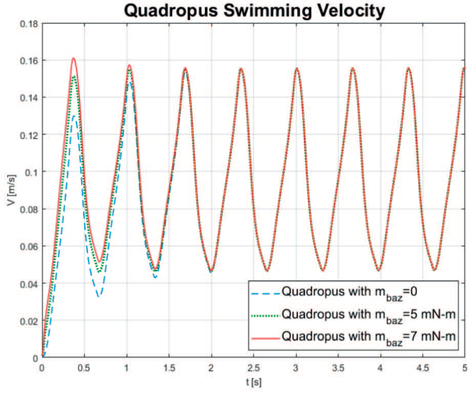
Comparison between the swimming performance of the Quadropus under different SRAs actuations.
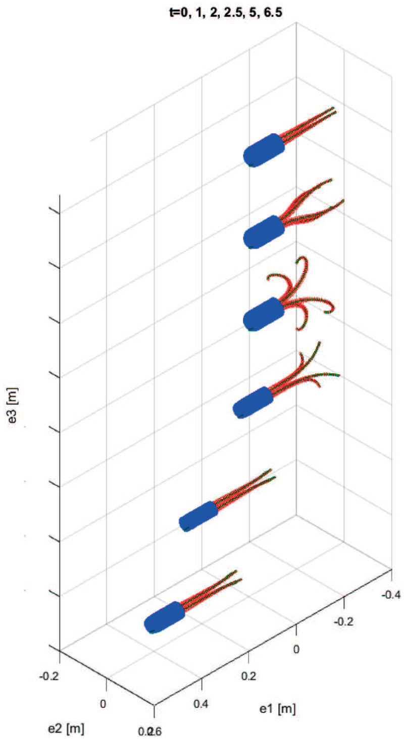
Few snapshots of the fast escaping maneuver of the Quadropus with active arms (
Decomposition of the force contributions to the whole-body dynamics from the actuated components can be observed in Figure 14. The force exerted by the arms at the three actuation values can be appreciated during the initial phase of arm expansion (
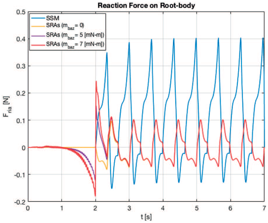
Comparison of force exchange between the arms and root-body in the three actuation scenarios. The load exerted by the pulsating shell is also reported.
We estimate efficiency of this system by using the definition of Maertens et al. (2015) for fish. This is the quasi-propulsive efficiency
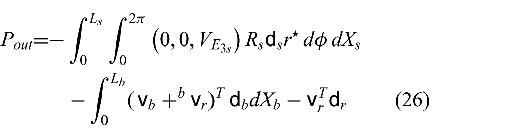
and the power required to actuate the pulsed jetting with

Because the analysis must be performed at steady state, the initial contribution from the sculling arms does not participate in the estimation of the quasi-propulsive efficiency. The comparison between actuation power and steady-swimming power is portrayed in Figure 15. Based on these, an estimate efficiency of 31% is inferred, which falls within the range of values observed for fish in Maertens et al. (2015).
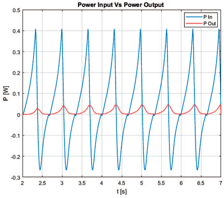
Comparison between the input and output power during swimming at steady-state conditions.
7.2. Monopus dynamics
A further example of the capabilities of the presented model is provided by the case of a sperm-like body actuated by the synergic actuation of a pulsed-jetting shell and by the flapping of a rear-pointing soft manipulator. The SRA, in this case, is studied as a mean of steering actuator for the system. This example lends itself to the analysis of the turning moments generated by the actuation of differential parts within the system. In this case, the SSM of the Monopus is actuated as in the previous example with a frequency of 1.51 pps, whereas the SRA is bent in different directions to produce a 6D underwater turning motion. The actuation wrench for the SRA takes the form
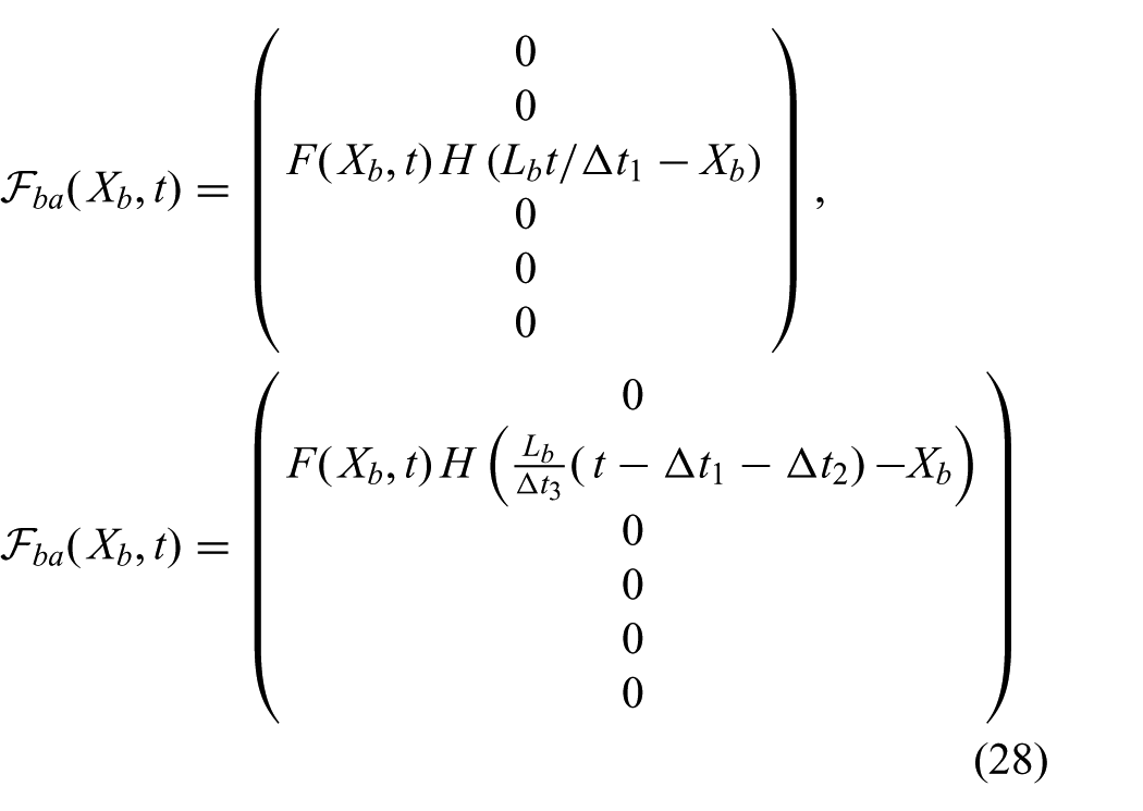
respectively for
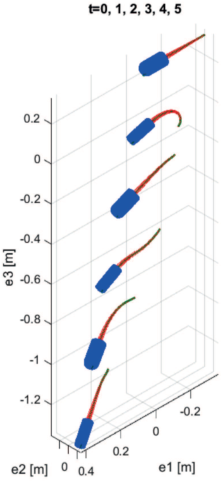
Few snapshots of the 6D underwater locomotion of the Monopus (
The dynamics of the Monopus is decomposed with the purpose of inferring baseline metrics that are commonly employed in manoeuvring tests of aquatic vehicles. With reference to the screw parameters (Murray et al., 1994):
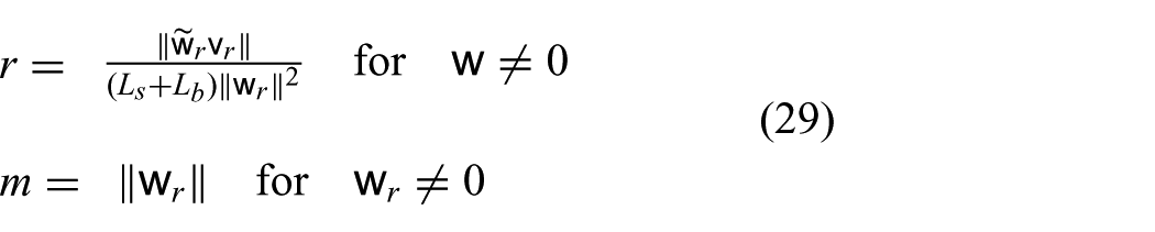
These enable the derivation of the non-dimensional time-dependent radius of curvature defined as the distance from the axis of rotation scaled by the total length of the Monopus (
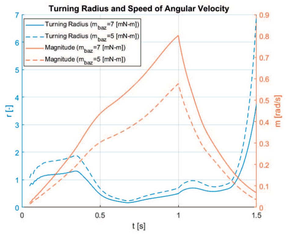
Turning radius and speed of angular velocity of the Monopus for two values of the SRA actuation.
8. Conclusion
In this work, a geometrically exact model for underwater soft robots is presented. The model is capable of representing a group of soft bodies connected together via a rigid root-body; this is done by taking into account the geometrical nonlinearity of the soft bodies (treated here as a Cosserat medium) along with the elastic responses, the mechanical actuation and the inertial loads exchanged by the interconnected bodies. This model is of general applicability since the dynamic equations of the soft bodies are derived from the unique knowledge of the Lagrangian density by means of a continuous extension of Poincaré’s equations. To the best of the authors’ knowledge, this is the first example in the literature where such a multi-soft-body geometrically exact model has been presented and used for the a priori evaluation of possible robotics design.
The work described in this manuscript constitutes the first milestone in our road map to the modeling and control of soft robots inspired from flexible aquatic organisms such as cephalopods. The difficulty to exhaustively address the coupled fluid–solid interactions acting upon the shell currently represents the major limitation of this formulation.
In particular, the model of the internal and external pressure due to the soft robot motion is simplified using the well-known solution of a one-dimensional momentum equation for a neutrally buoyant, rigid body translating in water (as explained in Renda et al. (2015b)) that drastically neglects potentially significant dynamical terms associated with body-shape modification. Indeed, the formal definition of the total propulsive force is simplified. Although it does not prevent the model from capturing the overall dynamics of the vehicle in surge motion, further refinements are sought for in order to attain a more sound representation of the complex physics involved in the system. Evidence is emerging that a substantial contribution to the total thrust of jetting bodies lies in the linked internal–external fluid dynamics of the collapsing shell. To acknowledge these terms in detail, a fully coupled fluid–structure interaction solver is mandatory. However, for the purpose of controller design and quick dynamics investigation, a fast and computationally inexpensive alternative must be looked into. This can be found from a coupled model that encompasses a quasi-analytic solutions of unsteady potential flows of radially varying slender, axisymmetric bodies (see Karamcheti (1966) and Anderson et al. (2001)) and an integral description of the internal pressure of the deforming cavity body, as in (Krieg and Mohseni, 2015). In this formulation, a prescribed kinematics of the shape-changing body enables the estimation of the added-mass variation as well as supplying the condition for accurate estimation of the forces generated by the expulsion of fluid across the nozzle. Despite the limited degree of reproducibility of the experiments, the model has been experimentally compared with a real multi-soft-body prototype with satisfactory results and then used to explore the design space of underwater soft robots characterized by different morphologies and actuation strategies. We show the varied range of dynamical analysis that can be performed on the newly designed conceptual prototypes by deriving quasi-propulsive efficiency of a four-arm pulsed-jetting octopus-like body and the time-dependent radius of curvature of a sperm-like vehicle. These demonstrate the capability of this mathematical formulation to represent an unlimited range of possible designs as well as to perform a priori evaluation of their maneuvering capabilities and swimming performances.
The authors believe that the versatility, accuracy and conceptual simplicity of the model presented here make this approach one of the most suitable in the frame of mobile soft robotics.
