
Abstract
Agile maneuvers are essential for robot-enabled complex tasks such as surgical procedures. Prior explorations on surgery autonomy are limited to feasibility study of completing a single task without systematically addressing generic manipulation safety across different tasks. We present an integrated planning and control framework for 6-DoF robotic instruments for pipeline automation of surgical tasks. We leverage the geometry of a robotic instrument and propose the nodal state space to represent the robot state in SE(3) space. Each elementary robot motion could be encoded by regulation of the state parameters via a dynamical system. This theoretically ensures that every in-process trajectory is globally feasible and stably reached to an admissible target, and the controller is of closed-form without computing 6-DoF inverse kinematics. Then, to plan the motion steps reliably, we propose an interactive (instant) goal state of the robot that transforms manipulation planning through desired path constraints into a goal-varying manipulation (GVM) problem. We detail how GVM could adaptively and smoothly plan the procedure (could proceed or rewind the process as needed) based on on-the-fly situations under dynamic or disturbed environment. Finally, we extend the above policy to characterize complete pipelines of various surgical tasks. Simulations show that our framework could smoothly solve twisted maneuvers while avoiding collisions. Physical experiments using the da Vinci Research Kit validates the capability of automating individual tasks including tissue debridement, dissection, and wound suturing. The results confirm good task-level consistency and reliability compared to state-of-the-art automation algorithms.
1. Introduction
Assisting multi-step dexterous manipulation tasks like minimally invasive surgical procedures is one of the primary directions in robotic applications. The well-identified advantages of augmented precision and stabilization, compared to manual handling, inherently offer advancement for positioning of surgical instruments. However, the up-to-date paradigm of robot-assisted minimally invasive surgery (RAMIS) still requires the surgeon to fully teleoperate the instruments throughout the surgery, or could only automate a single positioning step in ex-vivo environment (Kwoh et al., 1988). The surgeon’s mental concentration remains greatly demanded during the surgery, where the inconsistency in skill proficiency appears among novices and experts. Once they are automatically planned and executed under surgeon’s supervision, the human workload could then be effectively liberated and benefits task effectiveness.
The main goal of surgical task operation is to perform instrument motions and target contact safely according to task guidelines. Many surgical tasks in MIS (e.g., tissue dissection and suturing) comprise sequences of highly interactive motion sub-steps towards different targets. To cater for the minimally invasive setup, the instruments usually own a long, slender tool shaft with a wrist-like distal structure to enhance motion dexterity. However, task motions commonly encounter highly twisted motions (e.g., consecutive contacts to tissue/needle with inverted orientation). One or more states in SO(3) space might experience large-scale variation(s)
The challenges are then to define and ensure motion safety throughout the pipelines across different tasks. The primary concern is that there must be theoretical proof to support that the robot trajectory is feasible and also reachable to admissible target states. Each motion should also own re-planning strategy upon specific motion constraints to ensure proper contact to a (moving) target during multi-arm coordination. Other features including avoidance of obstacle collision and joint limits, real-time implementation, etc. should be solved as well. More importantly, the above features should be applicable to every elementary task motion throughout the pipeline of surgical tasks to avoid execution-level uncertainties. Planning trajectories for robot manipulators has been widely studied in industrial and/or domestic applications. Prevailing methods include generation of roadmaps (Siméon et al., 2004; Amato and Wu, 1996) and sampling-based methods (Berenson et al., 2009; Berenson et al., 2009) to directly explore the 6-DoF feasible trajectories. Meanwhile, on-the-fly planning/control schemes could be more efficient and reactive, for example, the potential field (Hwang and Ahuja, 1992) to attract/repel workspace constraints, but is subject to local minima that hinders target reachability. Aiming for surgery autonomy, most works adopt the above approaches to execute specified motions (Marinho et al., 2019) and/or a certain task (Sen et al., 2016) in surgery. Learning from demonstration is also utilized to deal with complex maneuvers like knot tying (Osa et al., 2017) and suturing (Schulman et al., 2013) to avoid direct path planning. We are unaware of any existing works that define generic safety motion constraints emerged from surgical tasks and apply them using a unified framework.
In this article, we present an integrated planning and control framework for 6-DoF robotic instruments for surgical task automation. The framework covers a globally stable manipulation controller, a reactive manipulation planning policy, and a generic motion primitive to characterize different surgical tasks. We first classify task-relevant surgical motions into two typical types. The first type is called tool-centric actions, where the robot end-effector is manipulated between (feasible) initial and final configurations without tentative contact to the target but might avoid obstacles. The second type is the target-centric actions, where the end-effector is delicately guided upon certain motion constraints to zero the remaining distance to the target for final contact. By leveraging the kinematic property of the instrument’s wrist geometry, the nodal vectors could directly parametrize the robot’s present-to-goal situation by a new set of parameter space, namely, the nodal state space (NSS). This avoids generating the (coupled) 6-DoF poses as a high-dimensional nonconvex manifold analysis that hinders globally stable manipulation. The robot trajectory is then generated and executed upon regulation of the states in NSS encoded by a dynamical system. The leading robot motion could be rigorously guaranteed stable and smooth under Lyapunov stability theory, and is further globally viable once the state regulation is coordinated by sequential motion allocation (SMA). We verify its capability to smoothly operate twisted maneuvers, which include drastic orientation changes inevitably occurred in surgical motions. Moreover, elementary motions within the task should be coordinated with situation awareness. To this end, we introduce a dynamic attraction state (DAS), whose dynamics is designed by NSS, as a “tunable” instant goal for active guidance of the robot’s movements. This transforms motion autonomy into a goal-varying manipulation (GVM) problem, which we could further detail the robot’s in-process trajectory through extra motion constraints for path versatility. We apply GVM as a reactive planning policy to ensure target-centric actions (e.g., repetitive needle grasping in suturing). By defining a bounded and robust DAS, GVM could adaptively proceed or rewind the contact motion based on on-the-fly situations. This could avoid hazardous movements while yielding a constrained path (e.g., unnecessary space intrusion or premature target collision). The framework provides a close-form motion output for tackling online motion constraints with guaranteed trajectory feasibility and target reachability. Such features are available for each elementary motion without using iterations. Finally, to elevate task-level generality, we extend such scheme to form different modes of behavior (MoBs), which facilitates depicting and automating pipelines of different tasks.
The main contributions of this work are summarized as follows: • A robot state model with skeleton nodes and the NSS for direct formulation of the present-to-goal situation for a robotic instrument based on its kinematic constraints. • A DS-based robot controller with synthesized SMA which provides global asymptotic stability proof that guarantees in-process trajectory feasibility and target reachability to an arbitrary (admissible) target. • The GVM reactive planning policy to facilitate bilateral transition between target contact and path following to smoothly deal with disturbed targets. • The motion primitive and its five MoBs which could define pipelines of different surgical tasks. • Simulations and physical experiments on different tasks are conducted for comprehensive validation.
Our previous works have addressed a few individual problems that target surgery autonomy. We have proposed an efficient and autonomous robot-camera calibration approach to compute the robotic instrument’s pose from a monocular camera for vision-guided instrument manipulation (Zhong et al., 2020). Aiming for autonomous suturing, a monocular-based 6-degree-of-freedom (6-DoF) pose estimation algorithm of a surgical needle has been developed (Zhong et al., 2016; Zhong & Liu, 2018), which was later implemented to a dual-arm needle insertion control scheme to increase needle insertion accuracy under deformation (Zhong et al., 2019).
The structure of this article is summarized as follows. Section 2 reviews the related works from manipulation planning and control approaches to surgery-specific explorations. Section 3 shows the problem formulation for this work. Section 4 introduces the new robot kinematics model for the robotic instrument using nodal state space. Section 5 elaborates the motion-level planning and control strategy and guaranty of safety and in-process constraints. In Section 6, we elevate the strategy to task-oriented modelling by characterizing different MoBs to form pipelines of different surgical tasks. Section 7 demonstrates the simulation results concentrating on motion-level performance study, and the experimental results in Section 8 show the overall task-level performance. Finally, discussions and conclusions are presented in Section 9.
2. Related works
Manipulation planning and control of 6-DoF manipulators subject to in-process constraints has been widely exploited in industrial and domestic applications. Most works target general workspace constraints, mainly for obstacle avoidance (Siméon et al., 2004; Stilman et al., 2007) and/or optimizing characteristics (e.g., avoiding singularities and deadlocks) (Li and Latombe, 1997; Ferbach and Barraquand, 1997), or to decide the sequence of motion profiles for a task (e.g., pushing a box and fetching an object) (Billard and Kragic, 2019; Fang et al., 2020). On the other hand, the motion pipeline required by a surgical task is complicated but clearly given in clinical practice (Cao et al., 1996). However, the wristed structure of the instrument and limited joint ranges render a smaller size of feasible space manifold and makes it challenging to coordinate the end-effector and whole-body motions. Only a few existing works tackle 6-DoF motion control of a robotic instrument, including learning from demonstration to perform a complex but single motion step like looping for knot tying (Osa et al., 2017). However, it requires collection of totally 4 datasets with
2.1. Automating basic motions
Pioneer works of robot-enabled instrument manipulation in surgical applications have targeted positioning of an instrument to registered poses, for example, the tissue cutter in prostatectomy (Kwoh et al., 1988) and the biopsy probe in neurosurgery (Davies et al., 1991). Combining clinical CT data, planning an optimal port placement and/or admissible path of the instrument becomes available to provide a safe referenced position for localized treatment (Schweikard et al., 1993; Adhami and Coste-Manière, 2003). Among these works, the concept of motion planning is limited to generating a deterministic path using an industrial robot arm for the instrument through admissible space without actual manipulation process or constraints. Funda et al. (1996) computed the optimal robot motion of for adjusting the gaze of the laparoscope subject to the remote center-of-motion constraint, which is widely adopted in MIS procedures. To include online feedback, Wei et al. (1997) applied visual servoing to adjust the robot-mounted laparoscope by tracking the instruments from the images. The method is also adopted in Krupa et al. (2003); Osa et al. (2010) to actuate a surgical instrument to a feature-defined target by minimizing image-based errors. However, the main disadvantage is that it requires continuous monitoring of visual features during manipulation, which could not robustly define a 6-DoF goal pose during the motion or provide re-planning strategy. To deal with multi-instrument environment, Preda et al. (2015) used sampling-based planning scheme (RRT-connected algorithm) for planning collision-free motion step for multiple instruments. Sozzi et al. (2019) proposed a DS-based approach with waypoint selection to actuate a non-wristed instrument with collision-free path to another instrument. The work in Marinho et al. (2019) proposed vector fields to guide the motion of a regular instrument with RCM constraint. Aiming for task-specific motion constraints, a few works adopt the method of learning from demonstration (LfD) to automate complex multi-arm coordinated trajectories like suture looping in knot tying or needle insertion (Osa et al., 2017; Schulman et al., 2013; Schwaner et al., 2021) to avoid modelling complex trajectories. However, it requires pre-recorded motion data for each type of task and is unable to deal with unexpected changes of task process. Notably, most above works used robot-mounted regular surgical instrument with only 4-DoF motions instead of a wristed robotic instrument. More recently, the work in Chiu et al. (2021) further introduced reinforcement learning (RL) policy to generate robotic instrument motions. To feed the online robot states to the system, continuous visual tracking of the instrument features is required via stereo images.
All previously mentioned works only focused on feasibility study completing a certain motion/task successfully, but failed to define generic safety features to be required by surgery automation to avoid execution-level uncertainties, which is of highest priority in surgeon’s perspective (Narazaki et al., 2006). There also lacks a unified solution to deploy those safety features across different tasks as well. In this work, we provide a DS-based framework with rigorous proof of global motion stability and trajectory reachability, such that it could handle stable motions to all task-relevant motions.
2.2. Automating contact motions
Interacting surgical instruments to the environment also constitutes a majority of motion steps in surgical tasks. In MIS, legitimate contact include non-invasive contact (e.g., palpation for tumor localization), grasping (e.g., toward a piece of tissue debris or surgical needle), and invasive contact (e.g., inserting a needle into tissue). To this end, Patil and Alterovtz (2010) addressed manipulation required for tissue retraction by selecting optimal grasping point, but didn’t specify the exact motion to safely grasp the tissue in advance. Since then, there are works addressing 6-DoF instrument-based manipulation of soft tissues for tissue dissection (Murali et al., 2015; Nagy et al., 2018) and deformation control (Li et al., 2020). The works in Kehoe et al. (2014); Hwang et al. (2020) automated target grasping in a peg transfer task, which is commonly used in surgical training for novice surgeons. Among them, the instrument targeting and grasping process were executed separately to avoid unsafe tool-target contact, and the grasping orientations highly resembled each other. Meanwhile, efforts have been made to needle grasping in wound suturing. Schulman et al. (2013) introduced LfD to automate manipulation and grasping of a needle with pre-recorded trajectories. The process had also been automated in terms of direct pick-up (D’Ettorre et al., 2018) and needle hand-off (Chiu et al., 2021; Pedram et al., 2020) using VS and LfD, respectively. A static needle was targeted and grasped using visual feedback as the motion input, which could reduce reliability when dealing with awkward grasping poses.
One mutual limitation of these works is that they all regarded grasping as separated steps with a fixed sequence rather than a reactive process, which could be re-planned under sensing/motion disturbances. The motion constraint during target contact should be embedded as well with the aforementioned safety features, but remains an unmet problem in surgery autonomy. We interleave manipulation and contact motion together as a GVM model, such that the robot will adaptively transit between tool-centric or target-centric actions with global stability.
2.3. Automating task-level procedures
Completing the pipeline of a surgical task based on step-level automation is the main goal to achieve task-level autonomy. Researchers have approached various individual surgical tasks with different sub-steps and different controllable DoFs required for the tasks. Works include autonomous field of view control of endoscope in Agustinos et al. (2014); Nageotte et al. (2006); Voros et al. (2006); Yang et al. (2019) that used VS technique to track a predefined visual feature to allow hands-free adjustment intraoperatively. In Kehoe et al. (2014) and Hwang et al. (2020), the authors targeted simulated surgical debridement with the instrument trajectories being performed using model predictive control and pose-to-pose interpolations, respectively. Given the targets’ positions, the instrument autonomously manipulated, grasped, and cleared the debris sequentially. Meanwhile, there are efforts targeting autonomy of tissue-based procedures, including non-invasive tasks like tissue palpation (McKinley et al., 2015; Nichols and Okamura, 2015) for tumor localization, and invasive tasks like tumor ablation (Hu et al., 2015), tissue dissection (Murali et al., 2015; Nagy et al., 2018), blood area detection, and suctioning from vessel rupture (Richter et al., 2021). Targeting more complex tasks like knot tying, Osa and Van Den Berg (Osa et al., 2010; Van Den Berg et al., 2010) automated single knot tying in suturing based on LfD.
Suturing is one of the most common but complicated tasks to be performed in MIS. It contains a long sequence of motion steps, involving dexterous manipulation of a needle and dual-arm coordination. Automating such tedious task could significantly reduce human workload, and thus has gained attention from researchers. For example, the works in Kapoor and Taylor (2008); Nageotte et al. (2005) have planned an optimal trajectory to automate the insertion process of a half-circle surgical needle into the tissue. A complete stitching automation process was given by Nageotte et al. (2009) including entry point planning, pose sensing, manipulation, and stitching of the suturing needle. However, these only constitute incomplete steps required by the suturing guideline. There are also studies addressing hand-off of the needle between two instruments using human–robot collaborative approach (Mikada et al., 2020; Watanabe et al., 2016, 2017), and also autonomous approach (Varier et al., 2020; Chiu et al., 2021) using RL-generated motions. Zhong et al. (Zhong et al., 2019) further addressed active tissue deformation during needle insertion to improve insertion accuracy. Lenard and Shademen (Leonard et al., 2014; Shademan et al., 2016) proposed a suturing device to inherently simplify the suturing task while ensuring a firm stitch. However, the needle size and stitch width could not be customized restricted by the tool. Meanwhile, only a few works have completed a throw of wound suturing. Sen et al. (Sen et al., 2016) provided an optimization-based approach to automate a four-throw suturing task, but does not support online trajectory re-planning due to tool-target motion disturbances with theoretical proof for motion stability. Pedram et al. (Pedram et al., 2020) completed an automatic single-throw suturing process using dual-arm coordination using a VS-based control framework. The instruments are visually tracked during the manipulation, which was reported to own accurate targeting accuracy. However, continuous visual sensing might hinder its applicability to deal with large orientation change. We are unaware of any existing works that provide systematic safety features for complex instrument manipulation in one or more surgical tasks.
3. Preliminaries
3.1. Problem formulation
Performing a surgical task is essentially to manipulate a robotic instrument from pose to pose in SE(3) space across all motion steps. Under any (instant) robot configurations, a 6-DoF goal pose of the robot’s end-effector (i.e., the instrument’s distal tool) is assumed to be available. It could be either computed from online sensoring feedback or from user input. One common method is to add image-based markers on the display (e.g., labeling the tissue’s dissecting trajectory or the wound position for suturing), as a surgeon’s decision and supervision remains critical to reduce uncertainties of target recognition in supervised robotic surgery (Haidegger, 2019). Although computerized surgical image analysis has gained considerable attention to assist target localization (Loukas, 2018), we emphasize that our aim in this work is an autonomous framework to perform robot motions safely and reliably instead of comprehensive detection algorithms.
Due to the delicate nature of surgical tasks, we define safety for task autonomy to be decomposed into the following two parts: 1) There must be theoretical proof to globally guarantee that the robot motion is admissible in every (future) time instant, and the goal state can be smoothly and stably arrived. The term “global” indicates it should apply for any admissible initial/final robot states, and 2) the robot motions must be able to deal with obstacle avoidance (both tool-tool and tool-tissue), joint limit avoidance, etc. The first part is of primary concern which has not been systematically addressed. The second part consists of basic safety properties. We especially target “twisted” motions where the distal articulated joints experience large-range adjustment
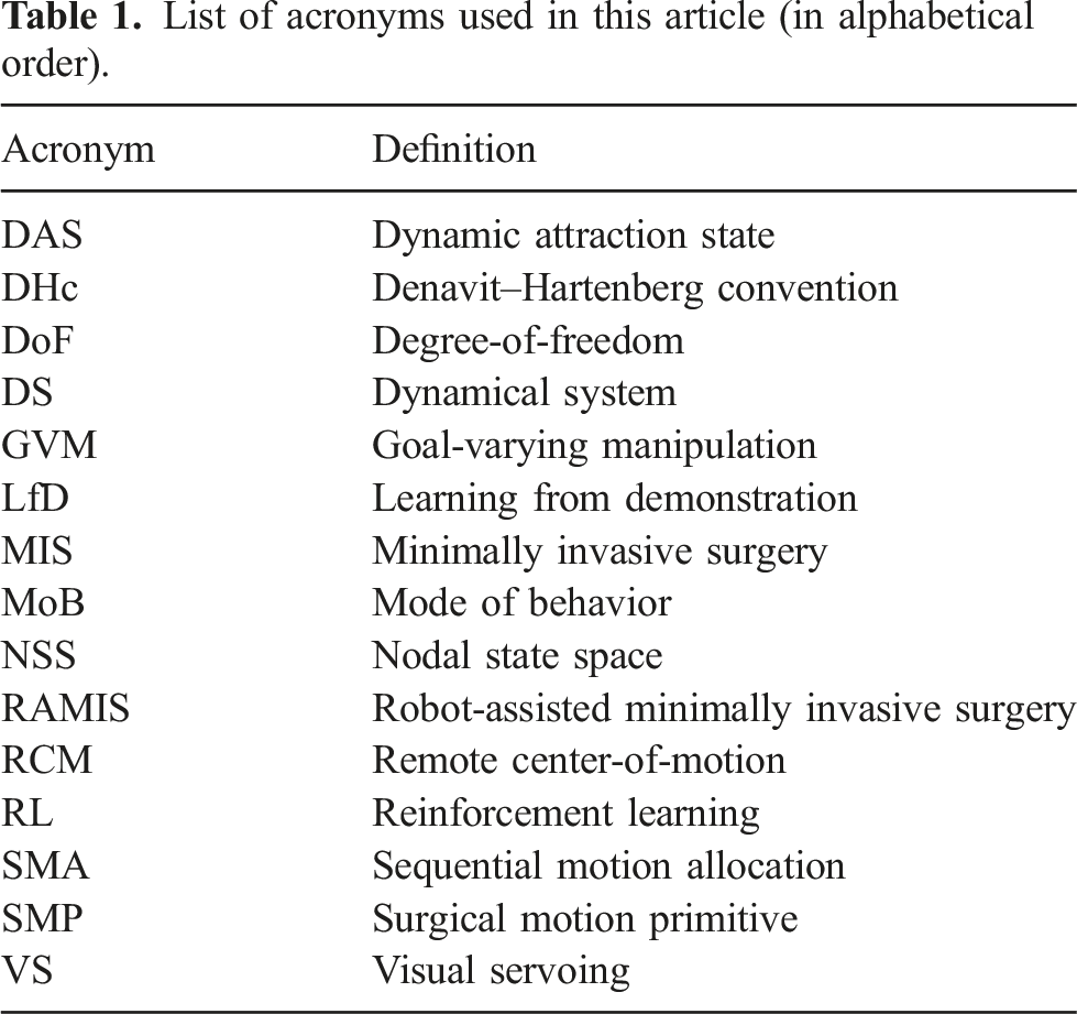
3.2. Nomenclature
List of acronyms used in this article (in alphabetical order).
4. Robotic instrument model
We begin by derive the kinematics of a robotic surgical instrument based on its mechanical properties. A typical serial-link manipulator generally owns six joints to fully determine the 6-DoF pose of the end-effector (SE(3) space) in 3D Cartesian space modelled by a coordinate frame 

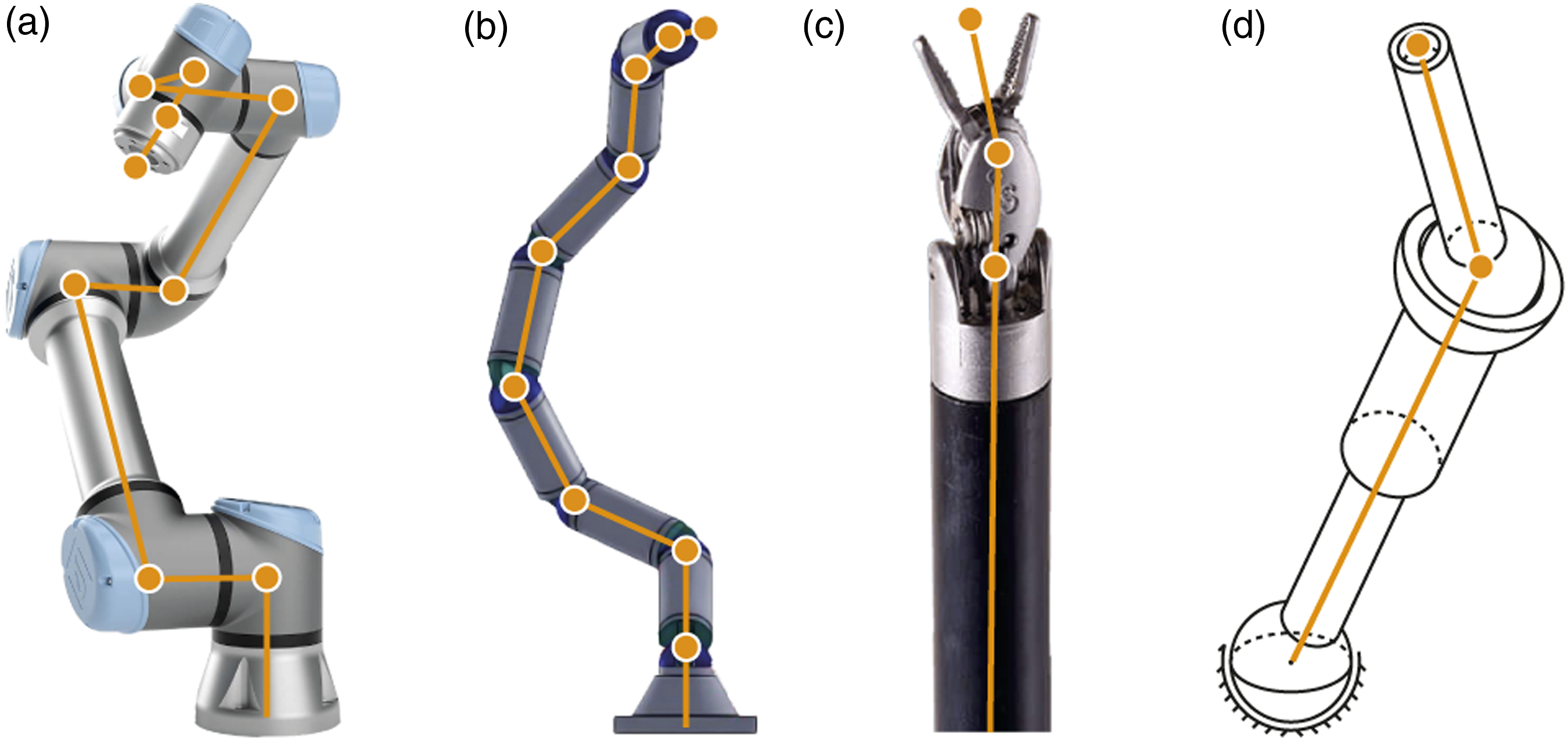
Then, adjustment of the end-effector’s pose will inevitably lead to movements for all six joints. Considering a complex motion step, the more “twisted” trajectory the end-effector undergoes, the more details are to be planned for describing its profile. Moreover, the limited joint motion ranges (±90° for the last two joints) results in a nonconvex reachable workspace manifold, where the path should be further refined to avoid all infeasible regions. Existing approaches deal with such trajectory complexity using a priori workspace analysis (Mirrazavi Salehian et al., 2018) or iterative optimization (Zucker et al., 2013), which could not guarantee real-time and/or theoretically feasible output in such high-dimensional space, and are unsuitable for surgical applications where the environment is usually temporarily set up and must not sacrifice efficiency. Thus, a new parametrization method is to be developed to reformulate the kinematic relationship between the robot’s proximal parts and its end-effector. Here, we introduce the concept of skeleton node analysis that regards each junction (or the “elbow”) between two consecutive links (or the “limbs”) along the robot skeleton as a point of interest. Specifically, we define a 3D point • It is the intersection point of the rotary axes of two consecutive robot joints. • It is the intersection point of the rotary axis of a robot joint and the geometric centerline of a link (regarding straight rigid links). • It is the origin of the end-effector’s 3D Cartesian coordinate frame.
Meanwhile, we disqualify a candidate if it overlaps an existing node which has already been defined from proximal robot parts. The general form of a node set considering a 6-DoF serial robot manipulator could be given as follows: The definition of “nodes” on different types of serial robot manipulators: a) the UR5 as a typical robot arm; b) a hyper-redundant robot arm (Li and Chen, 2015); c) the EndoWrist as a representative of robotic surgical instrument; and d) a highly wristed non-redundant robot with only three links (with DoFs being 3R-P-2R).

Normally, for an arbitrary node n i , i ∈ [1, k], there always exists a nonlinear and variable transformation between it and the end-effector (except ν k ) regarding its distal joints. No consistent geometric relationship between the nodal vectors and the end-effector could be derived.
We then use the skeleton nodes to analyze a robotic surgical instrument implemented to MIS. Without loss of generality, we consider the structure of the EndoWrist (by Intuitive Surgical Inc) which has been widely adopted for designing robotic surgical systems, and regard it as a typical example to study surgery autonomy.
1
The instrument owns a slender cylindrical shaft that provides 4-DoF RCM-constrained motions to yield the minimally invasive setup, a 2-DoF wristed joint set to provide wristed motions, and one extra DoF for tool actuation. Such kinematics leads its skeleton node set to be degenerated into the following form sufficed by k = 3: Kinematics of the wristed instrument and the illustration of the nodes and nodal vectors according to our definition.


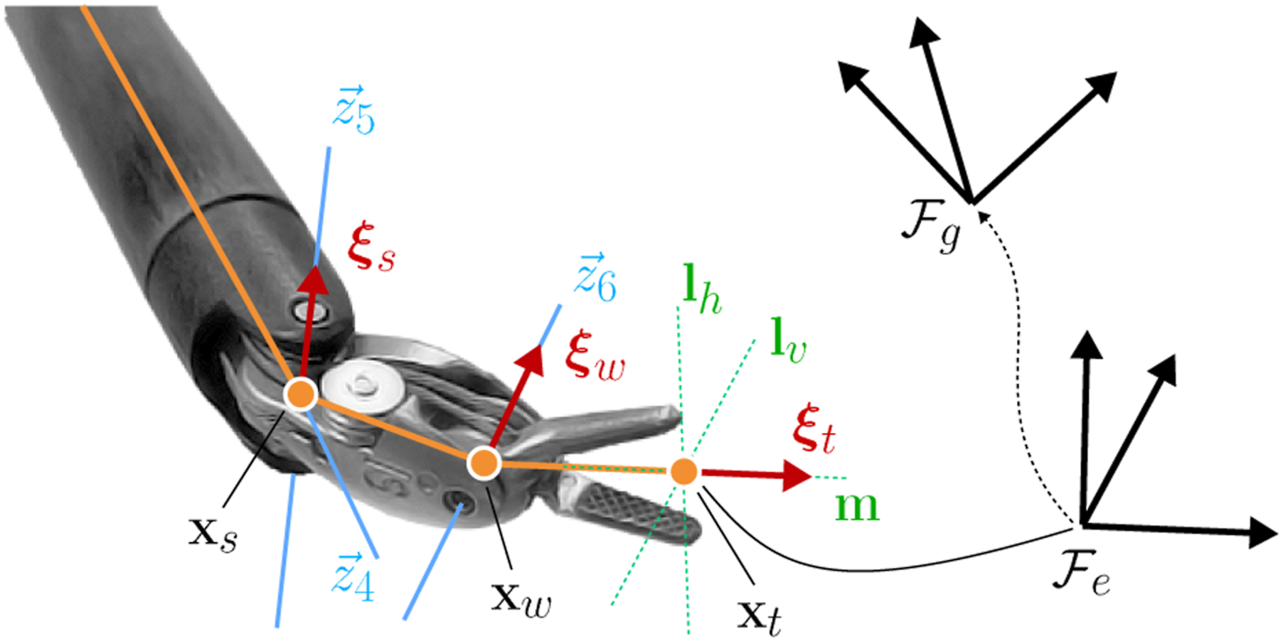
We decompose the robot joints correspondingly into the following:
5. Motion-level autonomy architecture
Based on the above modelling, we first aim to regulate the robot’s end-effector to reach an arbitrary (but feasible) goal pose by proposing a basic control architecture to provide safety features to the robot’s motions. We then extend it to yield more task-relevant motion constraints and utilize the derived properties to integrate a series of dexterous maneuvers into a single motion step.
5.1. DS-guided instrument manipulation
5.1.1. End-effector control system
The DS is an effective mathematical approach to generate stable, convergent robot motions which are efficiently reactive to instant state variations and/or disturbances. This endows DS-guided manipulation with powerful adaptability in motion re-planning without the need to analyze the entire trajectory (compared to optimization-based approaches), which is superior to tackle robot manipulation once the motion constraints are embedded into the system model.
We aim to incorporate the instrument’s kinematic property using NSS analysis to the DS to enable globally guaranteed safe instrument manipulation planning. We start by giving the general form of a time-invariant nonlinear dynamical system as follows:
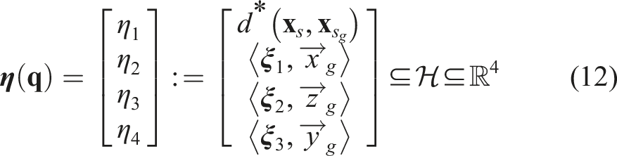

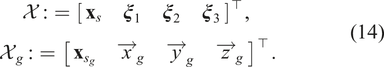
Now, we will use “state” in (14) to describe the robot’s status which is equivalent to a 3D Cartesian space, as we aim to solve automation via Cartesian workspace analysis. Several properties that NSS could contribute to robot motion guidance are highlighted.
Regarding η1, any given (feasible)
Given a 3D unit vector
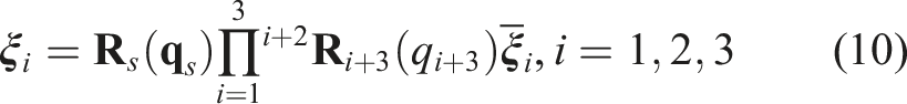
According to (10), the derivation of the nodal vector Now, we establish a dynamical system to guide the instrument end-effector to its target pose. The NSS 


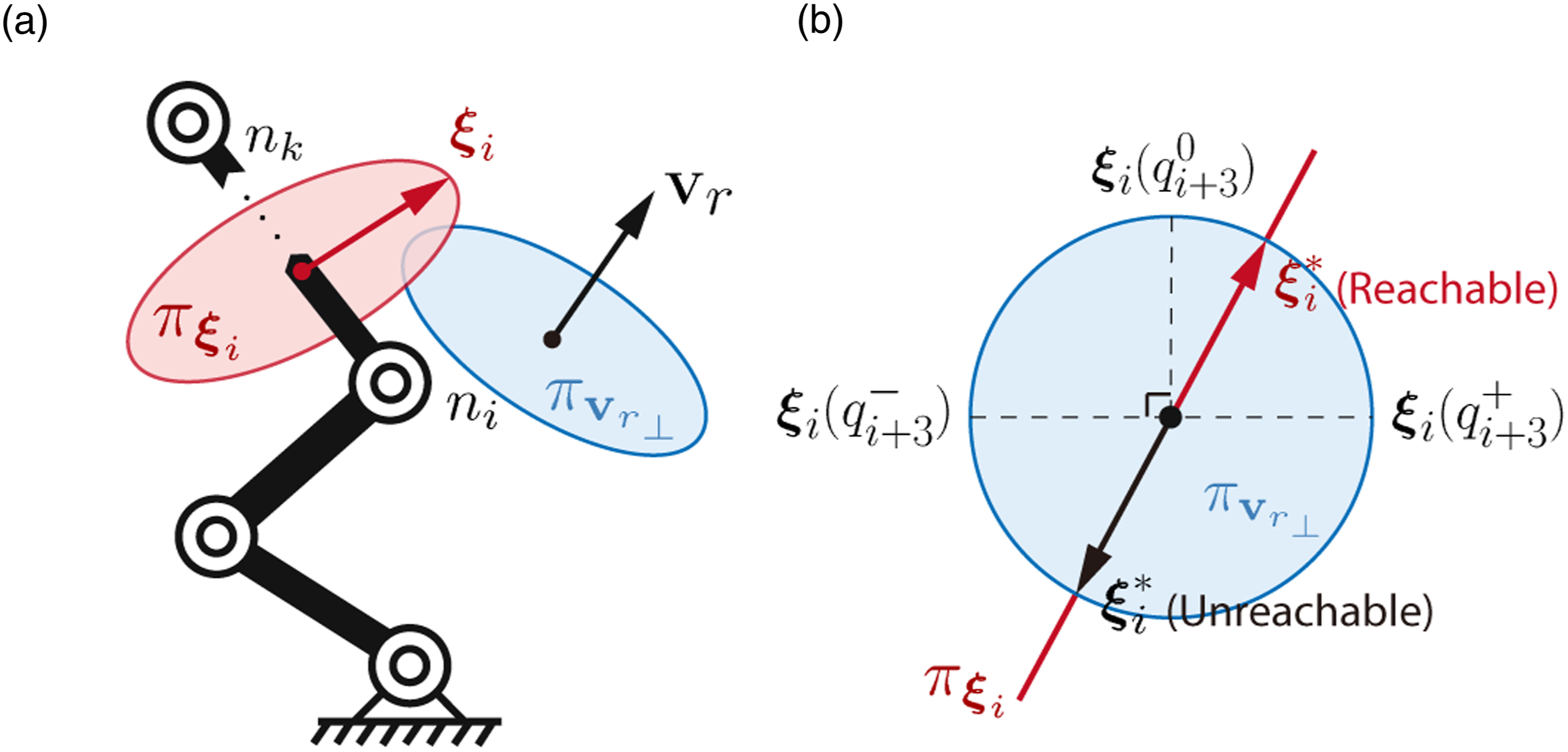
Geometric representation of the variability of
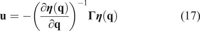
Deploying the controller (17) to robot’s target-reaching control requires interpretation of a
5.1.2. Sequential motion allocation (SMA)
The current form of DS only addresses the convergent motion of the end-effector to a goal pose and does not necessarily guarantee the feasibility of the in-process trajectory. Surgical tasks commonly require grasping the needle and tissue from specific poses to minimize potential trauma. When transitioning between awkward poses, the robot might encounter joint limits and/or near-singular configurations. In terms of a serial robot manipulator, one robot joint could parallelly tune different η. Therefore, regulating a specific η
i
might cause disturbances to other (distal)
To solve the above issues, new constraints must be added to the system improve the instrument’s manipulation delicacy. Here, we introduce the sequential motion allocation (SMA) that progressively allocates the regulation output from proximal to distal robot joints. This will facilitate “rhythmic” movements of the robot’s body parts and avoid “clumsy” joint motions, which could be harmful to both the robot and the environment. We achieve SMA by proposing a new set of state-based parameters 1. We set all coefficients to 2. To achieve sequential actuation of the skeleton nodes, the λ
i
that allocates the regulating motions to the current η
i
should initiate posterior to the elevation of the previous (proximal) λi−1. This is interpreted as λi−1 ≥ λ
i
∀λi−1, λ
i
∈ [0, 1]. 3. To incorporate SMA to whole-body coordination, λ
i
needs to open a gap to the rising λi−1 ahead, but also needs to catch up with λi−1 as λi−1 → 1 to eventually enable full regulation. This indicates the boundary conditions of λ
i
(x) to yield
All λ will constitute a space
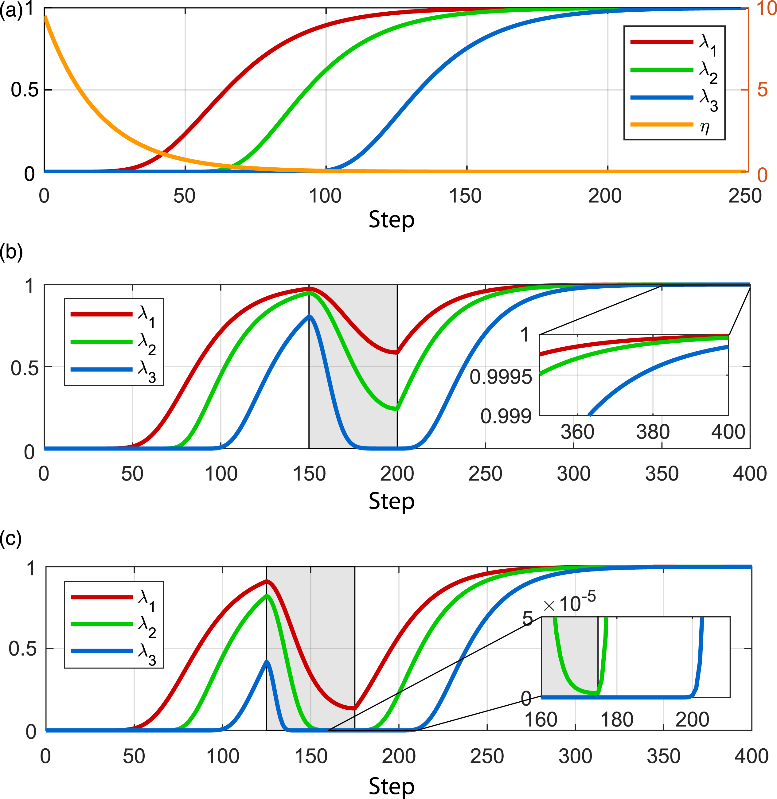
A feasible mathematical form of λ to achieve SMA could be given as follows: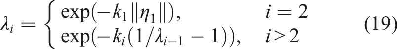

In (28), λ1 is only used as a reference to proceed the SMA under ||η1|| → 0, and at any time instant, deviation of η1 off 0 will suspend and restart the whole SMA process until η1 converges again. This implies the instrument’s position (via η1) is always regulated prior to the orientation (via η2,3,4) due to the “weak coupling” effect of the instrument’s end-effector pose. This is a demanding motion constraint in instrument manipulation, as the position misalignment of the end-effector caused by η1 becomes significantly larger than that by η2,3,4, also thanks to the “weak coupling” effect (see Appendix A for mathematical explanations how “weak coupling” appears on a wristed robotic instrument). One main advantage of introducing SMA to the DS-guided instrument manipulation is that the whole-body robot trajectory subject to (18) becomes always feasible. This is led by (28) which enforces the regulation of a specific η
i
, i > 1 to be always accompanied by a settling ηi−1. This further transforms the state space representation (12) into: Another explicit advantage of SMA is that the motion control of the robot’s end-effector and body parts does not rely on computing inverse kinematics and thus allows a differentiable system, which could guarantee efficiency and smoothness when dealing with complicated motions. Recall the goal position of 
Evolution of
5.1.3. Collision avoidance
In this part, we briefly introduce our framework to deal with obstacle avoidance. In robotic surgery, obstacle avoidance mainly solves two scenarios: tool-tool collision when performing dual-arm surgical tasks within a shared workspace, and tool-tissue collision to prevent trauma to surrounding tissues. As the obstacles might be described as a single obstacle 
5.2. Integrated planning and control
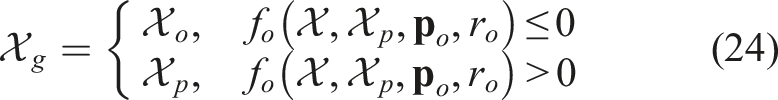
Apart from instrument manipulation, a majority of surgical instrument tasks (e.g., dissection and suturing) involve reaching and contact a specific target. The end-effector is normally manipulated to a proper candidate pose first (i.e., the tool-centric action) and then proceed to the final contact phase (i.e., the target-centric action) to could avoid unnecessary collisions or hazardous movements (Cao et al., 1996; Jun et al., 2012). Coordination between these two actions should be based on online awareness of the tool-target situation such that it could adaptively decide whether the robot is ready for contact or requires further adjustment. To this end, instead of regarding them as separated steps, we propose a unified strategy that integrates the tool-centric and target-centric actions to a single motion step to facilitate safer, smoother, and more efficient motion performance.
Recall the instrument’s goal configuration described by frame • • • 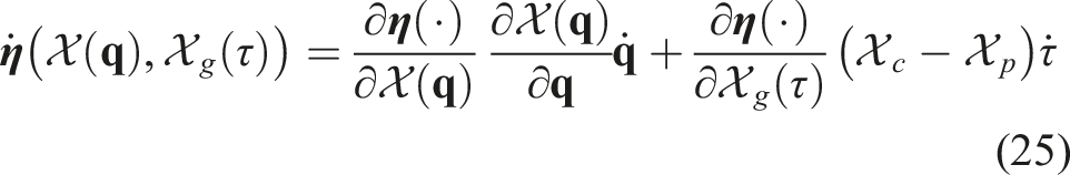
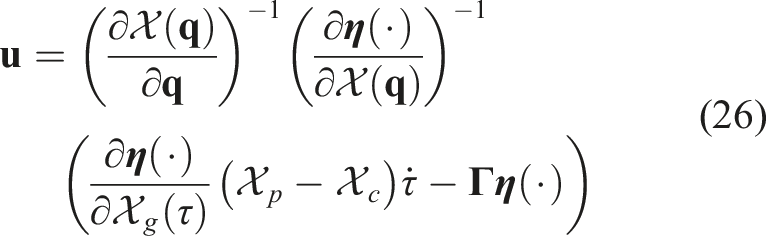


During the adjustment of τ, we regard
The above GVM framework could be used to automate typical instrument motions in robotic surgery. First, it could solve delicate motions required for target contact. We can simply define The schematic diagram of our integrated planning and control framework using NSS 
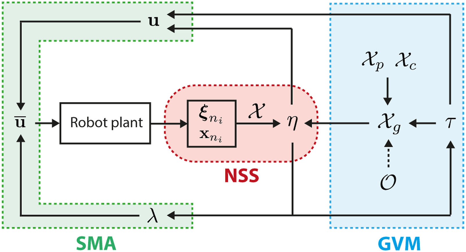
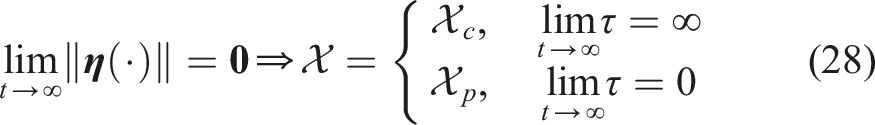
We briefly emphasize the superiority of our architecture from a combined technical and practical perspective that contributes to surgical applications. The introduction of NSS to represent the robot's present-to-goal variation provides distinct modelling advantages. The global asymptotic stability of (18) and (25) guarantees that the robot can be stably maneuvered to any arbitrary feasible state with smooth positions and velocities. Incorporating SMA then provides versatile planning of the robot’s goal-reaching trajectory as well. They solve the issues of “the robot could reach a goal” and “the robot knows how to reach a goal” simultaneously using our framework via a mathematically determined solver without prior knowledge or online iterations. GVM then plays a role to solve “the robot knows when to act” which picks up the last components required for a motion-level architecture. Its capability to transfer robot motion through different types of motions is illustrated in Figure 6. Conceptual illustration of different types of motion behavior achievable by using the GVM structure. The orange curve indicates the guided motion by the dynamic 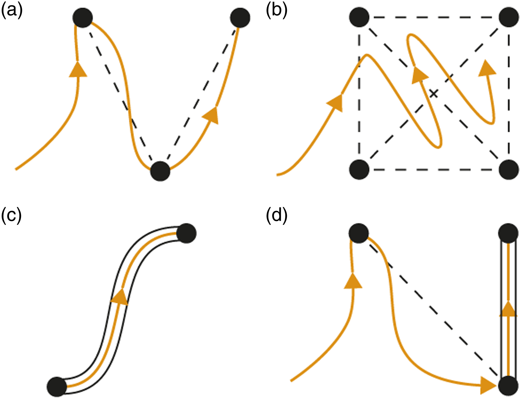
For surgical applicability, GVM allows motion constraints applied to the in-process trajectory, which makes it powerful to solve delicate target contact motions, where a constrained path is required to contact tissue via specified poses to avoid unnecessary tissue trauma. Particularly, the tool-centric action guarantees avoidance of premature contact to the target, and the instrument will not approach the target (at
6. Task-level autonomy architecture
In this section, we extend our approach to task-level automation such that it could complete the whole pipeline of one or more surgical tasks. The key issue is to further define a powerful motion descriptor that reveals the mutual behavior among individual motion steps while tolerating their underlying differences. GVM has enabled safe target contact by constraining the instrument motion delicately during the final motion phase. However, how to guide the instrument for clearance of the target or interact via specific path are similar but different steps to be considered.
6.1. Surgical motion primitive (SMP)
To systematically entail these motion details, we propose the notion of surgical motion primitive (SMP) based on GVM as a generalized model to define surgery-related instrument motions. The SMP characterizes a single-instrument manipulation step into three progressive phases:
•
•
•
The current setting of our GVM can only achieve consecutive execution across Phase II and Phase III. Thus, we must modify GVM such that it is applicable to the whole SMP. In this regard, we extend the validity of τ to Phase I such that it must retract the end-effector from the target to a safe position prior to Phase II. We define the initial pose as 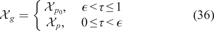
6.2. Modes of behavior (MoBs)
Finally, we utilize SMP to define and automate the entire pipeline of instrument motion sequences for different surgical tasks. Although we define three consecutive phases that form the single SMP, some instrument motion steps might only involve one or two of them. For example, an off-target manipulation can be fully performed by initiating only Phase II. Retracting the instrument from an object to a stand-by contact-free target could be done by using Phase I and Phase II. To make SMP customizable to such motion differences, we combine different motion phases and generate the following five typical modes with their application scenarios: • • • • •
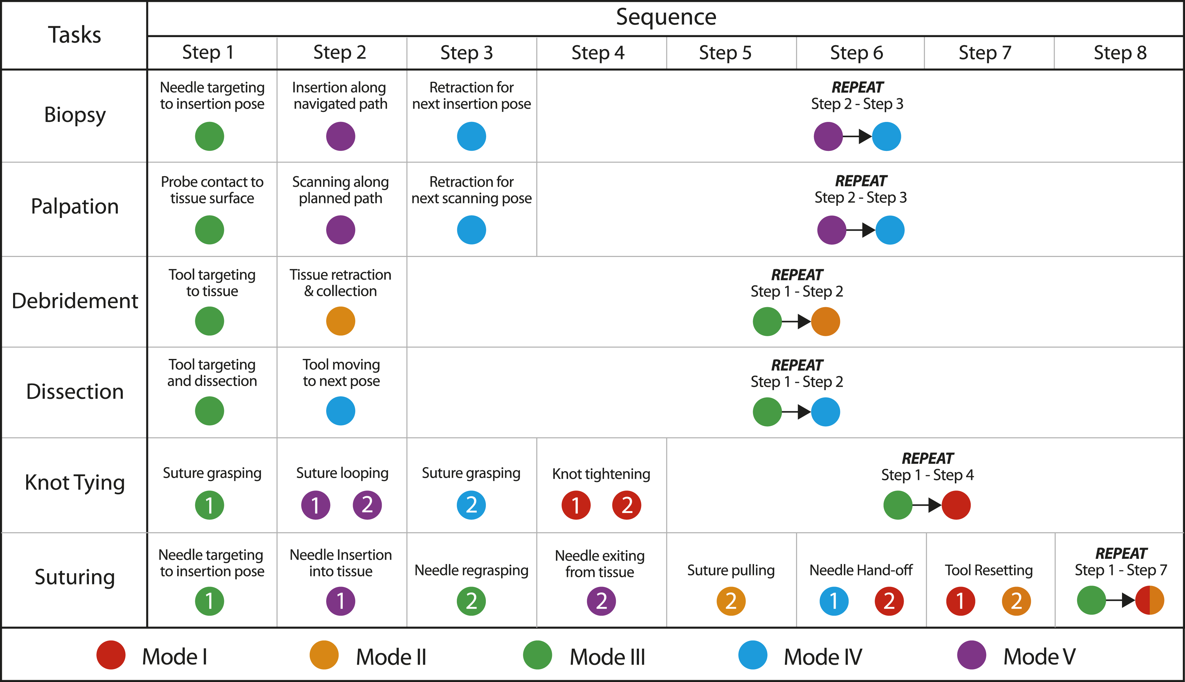
They are also defined as the MoBs, as they exhibit own motion constraints while sharing the identical control architecture, and are available to each SMP (see Figure 7 for conceptual illustration). To achieve task-level autonomy, we first utilize a chain of SMPs that govern each motion step in the surgical task to construct the whole pipeline. Then, we equip each SMP (or each motion step) with a specific MoB according to its prescribed functionality. As the guidelines for surgical tasks are already mature in clinical practice, the MoBs could be preset for each task such that it could successfully follow the procedure. In Figure 8, we demonstrate the applicability of our framework to characterize many different existing surgical tasks by selecting different SMPs and MoBs, based on clinically adopted surgical guidelines (Cao et al., 1996). The validity covers not only intra-corporeal MIS procedures (e.g., tissue dissection, wound suturing, and knot tying) but also other procedures like robotic palpation and biopsy, which is generalized framework compared to existing task-specific approaches. Although each elementary motion has different constraints, they could be set by five modes of behavior to form a pipeline. For example, the specification for dual-arm suturing could be easily interpreted as 3-5-0-0-0-4-1 for PSM 1 and 0-0-3-5-2-1-2 for PSM 2 (where 0 means staying idle in this step). This could all be preset in the framework as long as the task type to be automated is determined, which is very easy to specify. We will show later in our experiments that the ability of coordinating motion execution process adapting to the online robot-environment situation is critical to improve the success rate and reliability of task autonomy. The five modes of behaviors (MoBs) proposed based on our planning and control framework to define individual motion steps in various tasks. Mode I: free reaching, Mode II: constrained retraction with free reaching, Mode III: constrained reaching, Mode IV: constrained retraction and reaching, Mode V: trajectory tracking. Demonstration of complete pipelines of various independent surgical tasks which could be fully formulated by our framework using the five MoBs for task automation.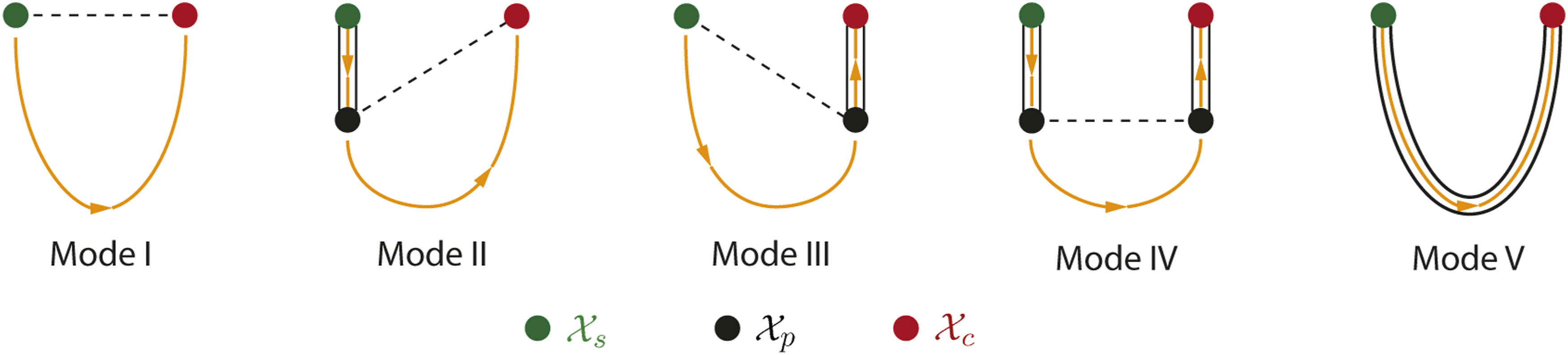
7. Simulations and Results
In this section, we present our simulation setup and results to demonstrate the motion-level performance of robotic instrument manipulation. The simulations will be conducted to reveal the following two main aspects of our approach: How the robot motions are actuated to deal with delicate and drastic manipulation steps, and how the strategy reacts to different tool-target configurations when attempting to perform interaction to a physical target.
7.1. Overview
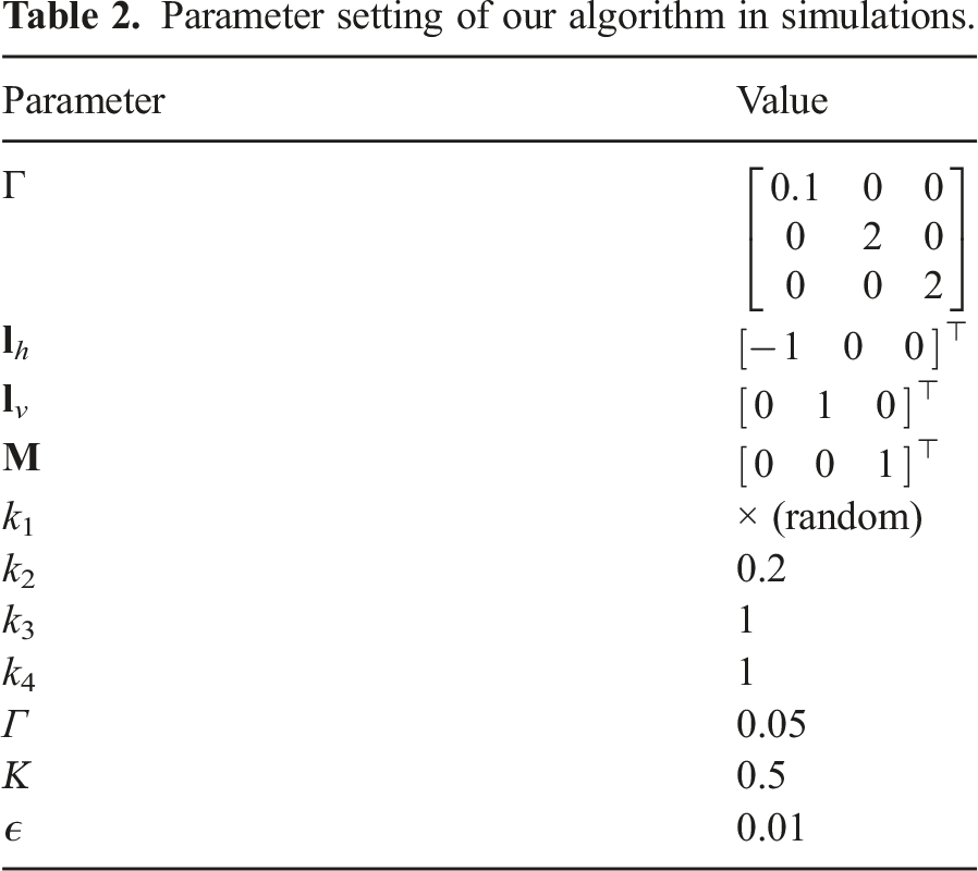
Parameter setting of our algorithm in simulations.
7.2. Scene I: Complex tool manipulation
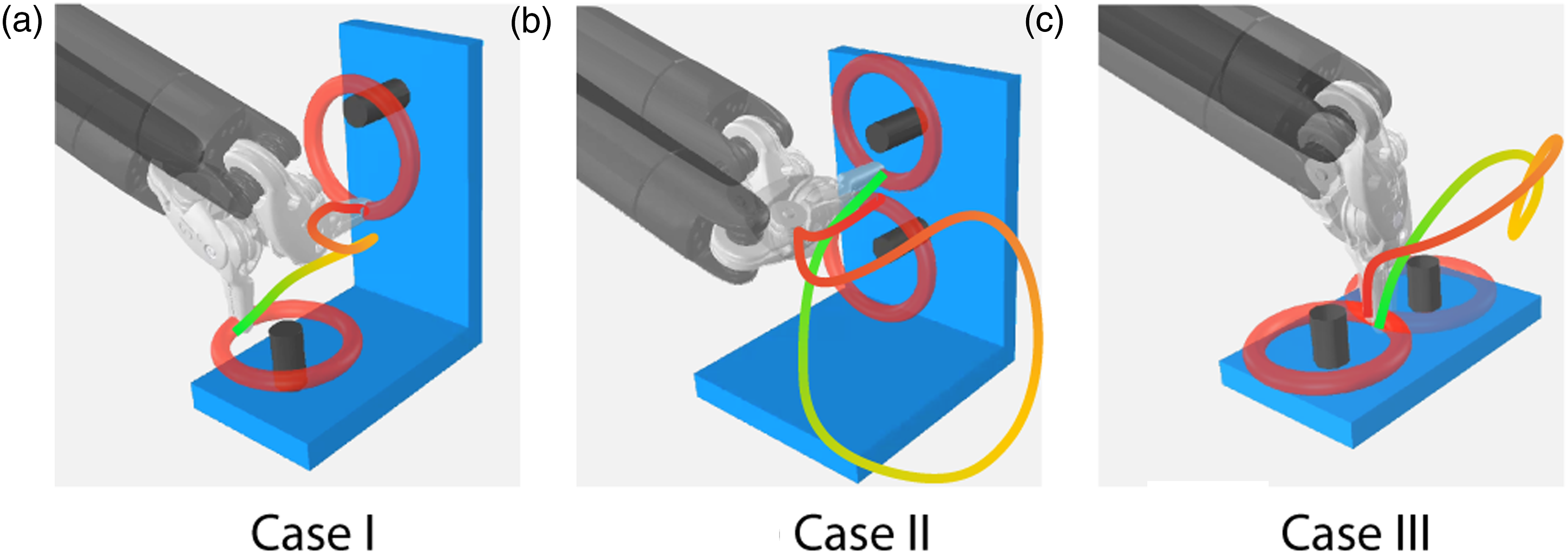
We first simulate a peg-transfer setup where a plastic ring is to be manipulated by the robot from one peg to another, which is commonly used in surgical skill training for novice surgeons. The initial/final state of the pegs is usually selected that corresponds to awkward robot configurations (i.e., either near-singularity or near-limit joint states). The robot trajectory needs to experience large-range orientation adjustment in order to align the ring to the peg to finish the manipulation properly, which might be hard to plan within confined space. To verify the validity of our framework to tackle such extreme scenarios, we assign three typical cases, as shown in Figure 9: • Case I: Transfer the ring from a horizontal peg to an adjacent vertical peg. • Case II: Transfer the ring from a horizontal peg to another horizontal peg by twisting the shaft through 180 degrees. • Case III: Transfer the ring from a vertical peg to another vertical peg by twisting the shaft through 180 degrees. The three cases of pose-to-pose manipulation for simulated peg transfer tasks where the instrument needs to drastically twist the wrist. The end-effector trajectories are visualized from green to red along the evolution of time.
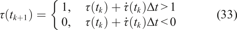
The target states of the robot are known and remain static at this stage of simulation. The process is actuated using Mode III for our proposed SMP. Particularly, the differences between initial and final positions of the distal joints Evolution of distal joint positions for three cases of complex manipulation. The gray areas denote the −π/2, π/2 feasible joint range available to both q5 and q6, where motion control without SMA tends to overshoot the joint positions before convergence, which might enter unreachable regions under near-limit configurations.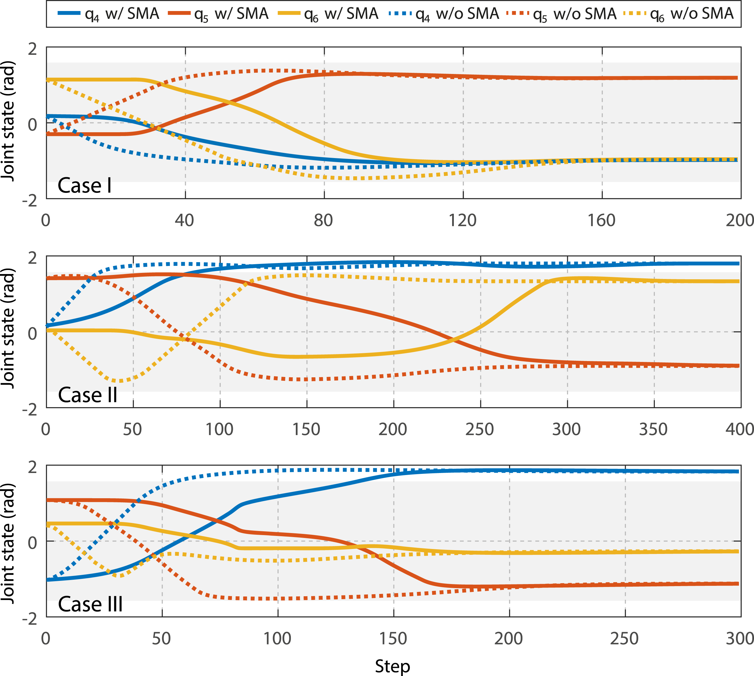
Then, we verify the capability of GVM to inherently avoid unnecessary contact to the target during manipulation. The main symbol of inadvertent tool-target collision is the time instant(s) that the end-effector position goes behind the target contact point, which is mathematically interpreted by the following metric:
Guiding the end-effector through Instrument end-effector position error during target-reaching manipulation in the three cases with and without using GVM-based guidance. The red parts indicate the time instants where target intrusion happens (i.e., ϕ < 0).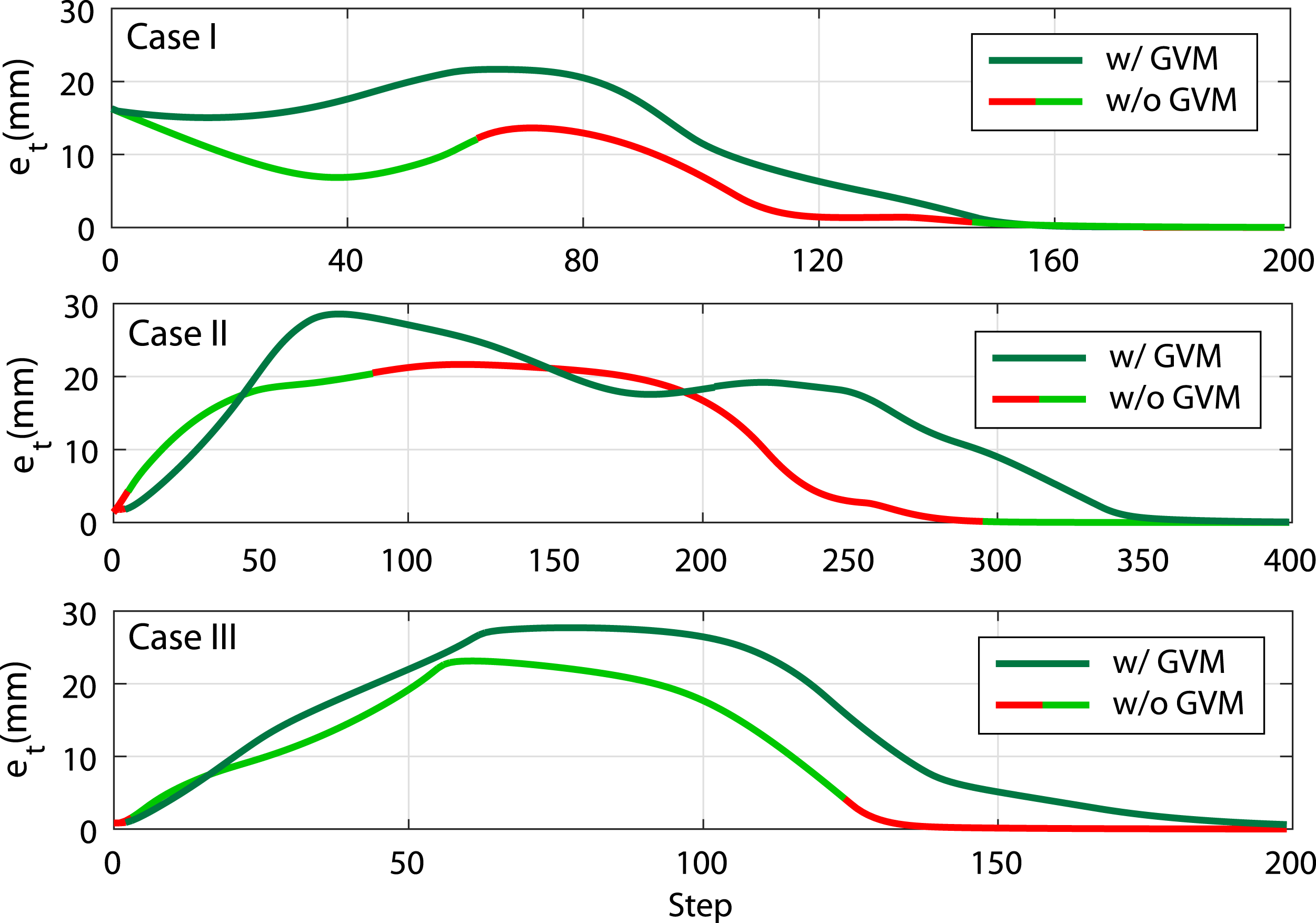
7.3. Scene II: Dual-arm collision avoidance
Then, we investigate the applicability of our algorithm to deal with collision avoidance. Aiming for a common but challenging scenario in robotic surgery, we consider a tool-tool collision situation where two robotic instruments are manipulated to their respective targets, respectively, and have to move close to each other within shared workspace. The initial and final states of two instruments are defined such that their trajectories will make the robot skeleton collide to each other if no avoidance is actuated.
Figure 12 shows the setup of this scene and the simulation snapshots for the dual-arm manipulation considering tool-tool collision avoidance. Our framework allows simultaneously dual-arm collision avoidance as the planning strategy is decentralized. The minimum tolerant distance is set to 10 mm as the tool shaft size is 8 mm, leaving the minimum tool-tool distance to be 2 mm. Both two instruments start collision avoidance as soon as the process begins and consider the other one as the moving obstacle. By inspecting the instant nearest obstacle point on the skeleton, two shafts move around each other and retract the distal part to prevent the whole robot from collision. After the other instrument stays clear from its target, the instrument proceeds on the tool-centric action and target-centric action. Simulation snapshots of dual-arm manipulation for ring grasping with tool-tool collision avoidance that evolutes as a)-d). In d), the back-projected instrument end-effector positions are shown that move from green to red.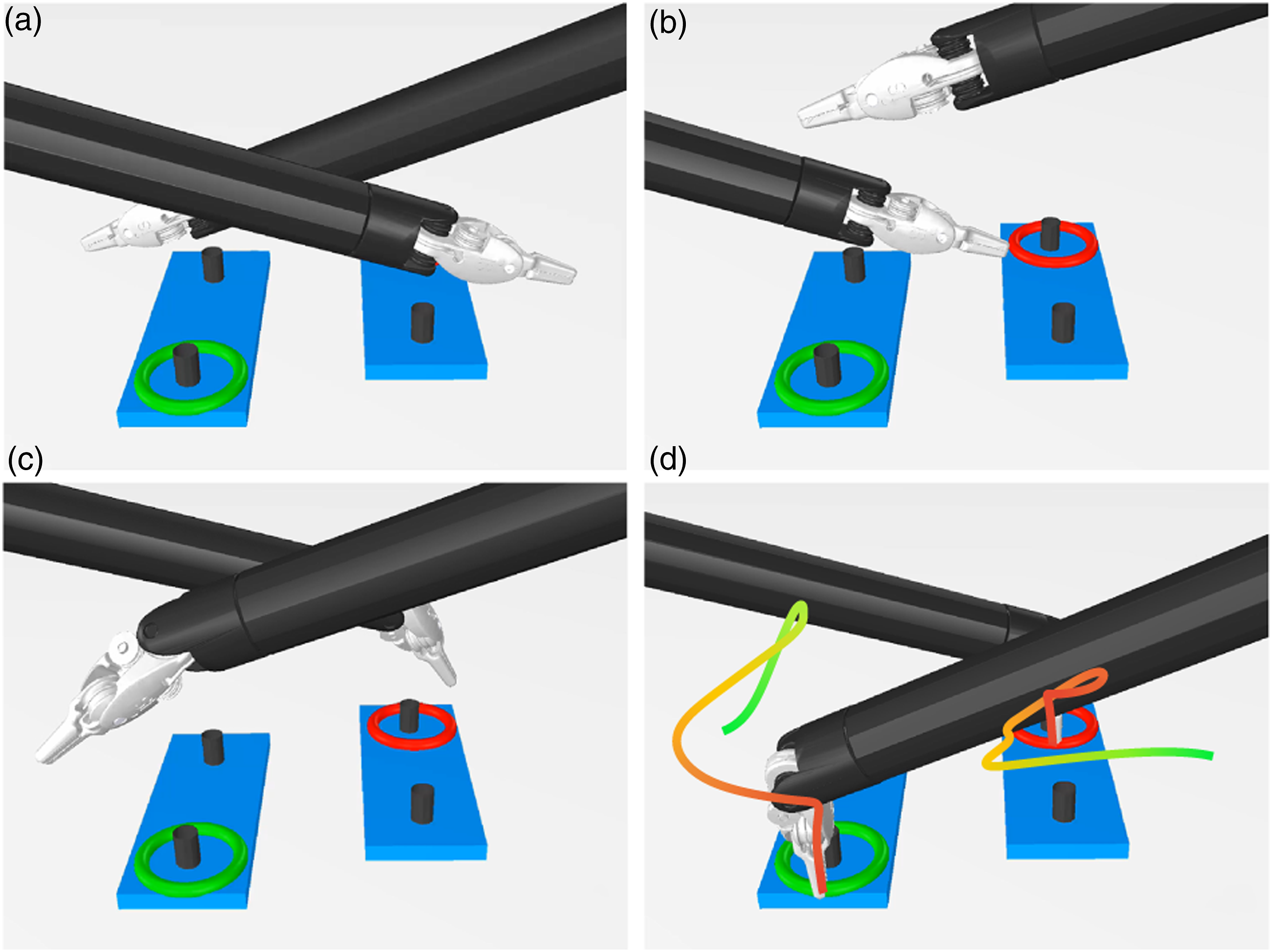
Figure 13 shows the resultant dual-arm trajectories. For comparison, the trajectories for direct target reaching are shown as well. It is clear that to avoid collision, the trajectories are more complex, but remain smooth and do not affect the subsequent target-reaching process where a constrained path is required. The collision avoidance input only applies on demand when the obstacle obstructs target reaching, and will smoothly fade once the obstacle is clear. Motion trajectories of two robotic instruments during simultaneous ring grasping in Scene II (described by the base of PSM1 in mm) with and without applying collision avoidance. The green/red dots indicate initial/final positions of two robot end-effectors, respectively.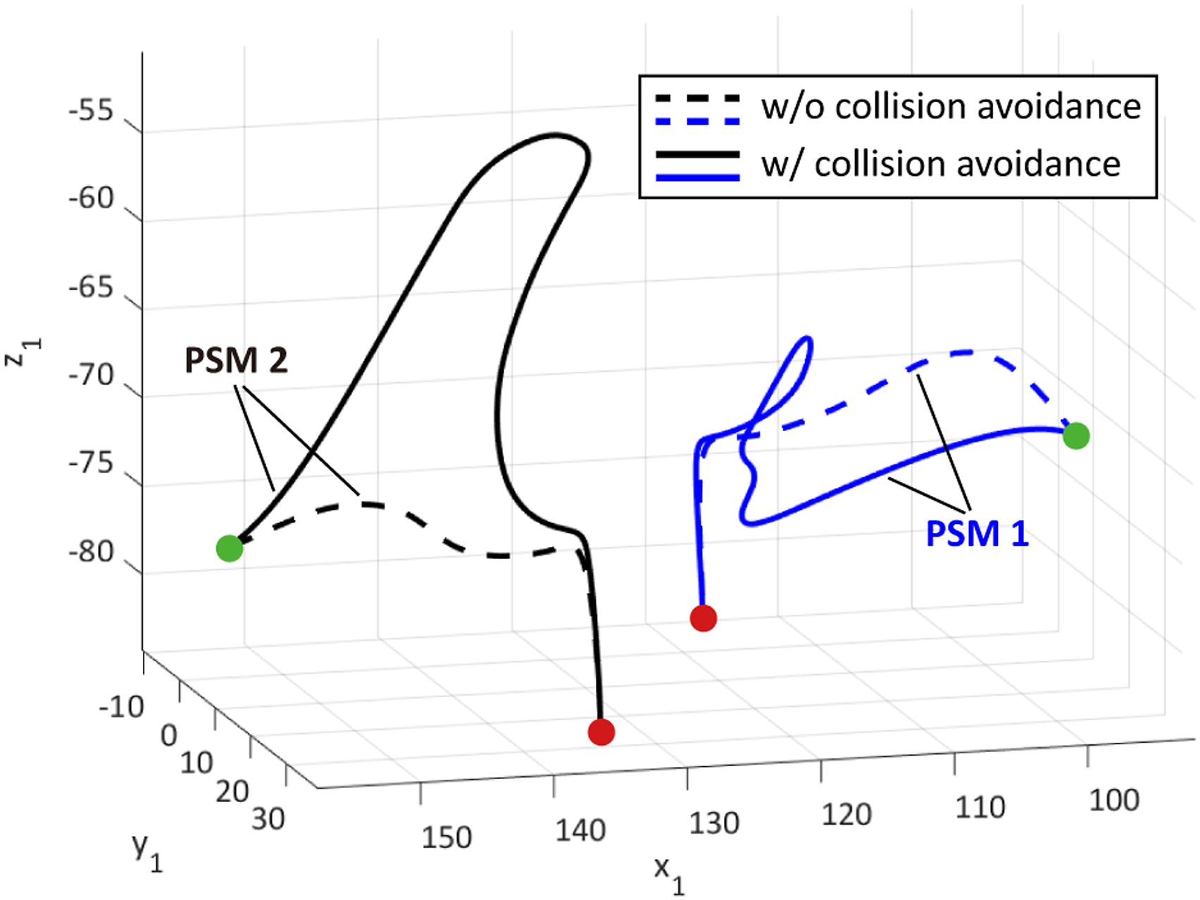
7.4. Scene III: Perturbed interaction
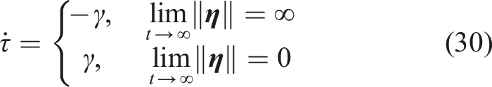
In this subsection, we validate the motion performance of the instrument when reacting to different target situations led by the GVM. A typical action during surgery is to manipulate the instrument’s distal tool from a safe idle configuration to contacting a target object, usually for grasping purposes. The contact must be made via a proper reaching pose to ensure safe tool-target interaction. We use a half-circle (or 1/2) surgical needle as a target, where the robot aims to grasp the needle body at its two-thirds curvature point as a standard needle pick-up procedure. The needle is attached to a support to visually emphasize its pose change during simulation, which is also known to the robot’s base. Again, we apply Mode III motion behavior to the instrument, where Illustration of pre-grasp manipulation and final constrained target contact planning and control upon evolution of τ based on (30). Evolution of two examples of target reaching shows that orientation is alignment in tool-centric action phase and then comes to translation to eliminate the remaining distance to avoid premature collision.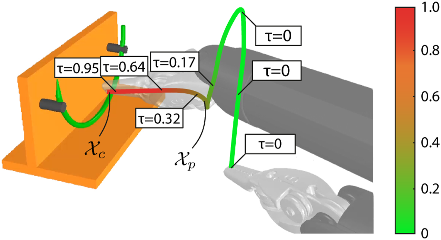
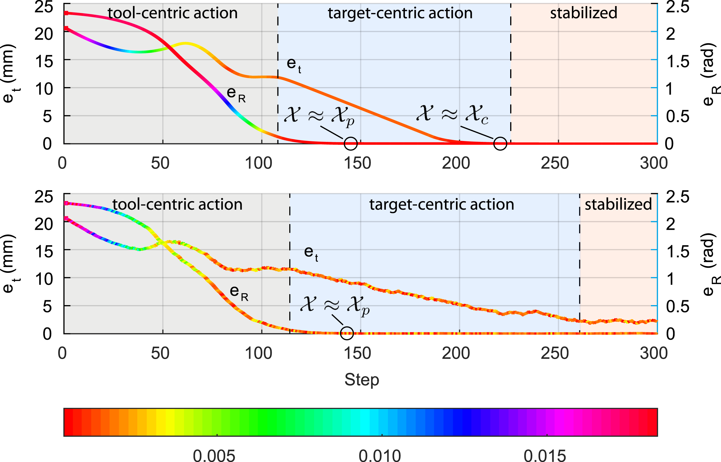
We next study how GVM will react to a target under different situations. The target pose of the robot might be perturbed, where the disturbances could be from sensoring noises or physiological motions during surgical procedures. We add uniform random noises to the target 3D position with the magnitude of 0.003 mm for all axial directions and is deployed throughout the process. The orientation remains unchanged at this stage. The comparison of the target-reaching motion performance with and without applying noises is shown in Figure 15. It is clear that the perturbed setting results in not only longer convergent time of the tool’s position e
To further study the robot motion behavior using our system to deal with target disturbances, we apply different noises to the identical setup and further obtain the relationship between the e
Stabilized end-effector distance from the final contact state 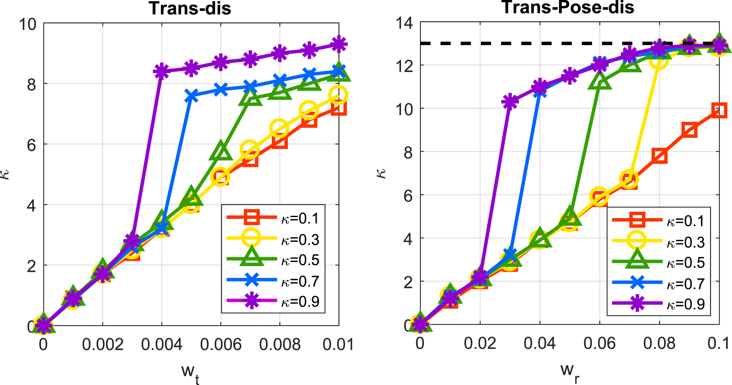
7.5. Scene IV: Target-varying interaction
Finally, we conduct simulation based on Scene II to study how our framework could deal with a moving target. The instrument might reach a target which is being moved by another instrument (e.g., needle hand-off in wound suturing) or need to follow specific trajectories, such as needle insertion into tissue and palpation through tissue surfaces. The target is either moving or to be moved after being grasped. Here, we propose the following three typical cases that cover different target motion types to further evaluate the applicability of our framework to different manipulation strategies: • Reaching an intermittently moving target along a linear trajectory with unchanged orientation. • Reaching a continuously moving target along a pose-varying trajectory (moving position and orientation). • Tracking an arc-shape trajectory (moving position and orientation).
The first and second cases that correspond to decentralized dual-arm coordination for target hand-off are set. In the first case, the final contact position Resultant trajectories of the instrument in all three cases in Simulation Scene III. The orange and blue curve represents the target and the instrument’s end-effector position, respectively. The curve with changing color between green and red is the trajectory of the pre-grasp point, or the position evolution corresponding to 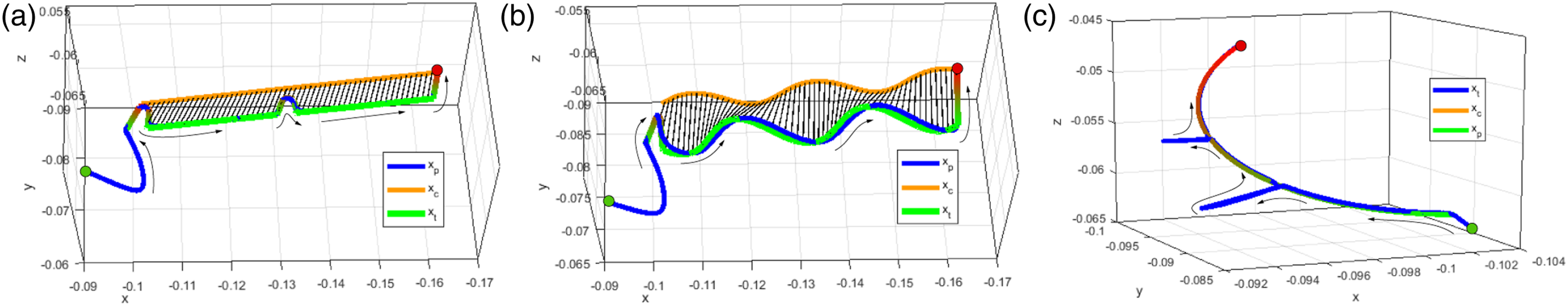
Case II is similar to Case I but with 6-DoF pose change over time. By reserving the translation motion of the needle, we add rotary motion of the needle with respect to its own frame, that is, 0.15* sin 0.025t rad along y-axis and 0.25* sin 0.025t along z-axis. The motion starts at t = 150 and continuously lasts for δt = 600. As shown in Figure 17(b), the end-effector manages to track the moving
In Case III, we show how GVM contribute to stable trajectory tracking of the instrument. We first define an arc-shaped trajectory whose distance to the rotation center is 15 mm, and the total equivalent rotation range is 2/3π. Such needle insertion path is commonly used in MIS to minimize tissue trauma during penetration. The GVP τ becomes the parametric value that guides
7.6. Summary of simulations
The simulation results demonstrate the motion-level behavior of our robot planning and control framework in different scenes. Overall, the GVM method is validated to be capable to dealing with the following three scenarios: • Pose transfer through extreme configurations: The planning and control motions remain feasible and efficient to large-range pose adjustment ( • Stable and reactive target contact: The robot motion is guided via a bidirectional manner, that is, robot adaptively decides whether to reach or to stay clear from the target by evaluating the on-the-fly tool-target configuration. • Smooth trajectory tracking: The robot is capable of following a predefined path with controller disturbances, where the tracking process automatically halts due to path deviation and will proceed after the deviation is cleared.
Basically, the framework provides a reactive planning and control process which could be used to characterized different types of elementary steps in surgical procedures, and could lead to a “fail-in-safety” performance which highly reacts to the on-the-fly information. This is essential to further improve task-level reliability when automating a sequence of motion steps in order to complete a task successfully. The quantified results will be later addressed in experiments.
8. Experiments and Results
8.1. System setup
In this section, we present results of on-site experiments for the robot to automatically perform simulated surgical tasks. We use a dVRK with two PSMs as the robot platform. Both PSMs are equipped with LNDs, which is a common type of instrument adopted when conducting tissue arrangement and suturing in RAMIS. Both instruments have a 7-DoF joint set with the first four accounting for the RCM motions for minimally invasive setup, the middle two joints for providing wristed motions, and the last DoF for controlling the tool actuation (or the jaw opening angle). The physical setup is shown in Figure 18. We use a Core i7 3.4 GHz user-side PC controller (with 156 GB RAM and without GPU acceleration) which connects to the robot controller with TCP/TP. The cisst/SAW software environment is used and the algorithms run in MATLAB 2020b under the Robot Operating System (ROS). A pair of industrial CMOS cameras is used for online visual feedback data acquisition with 640 × 480 resolution and 30 frames per second. The base position of the two robots (i.e., the RCM) is set such that their distances to the target to be operated are both around 150 mm, which is commonly adopted in the clinical practice of RAMIS. The camera is fixed between two PSMs, which is a typical setup scale for multi-port RAMIS (Escobar and Falcone, 2014). The positions of the left camera relative to PSM1 and PSM2 are [34.5, 70.2, 39.1]
The experimental setup.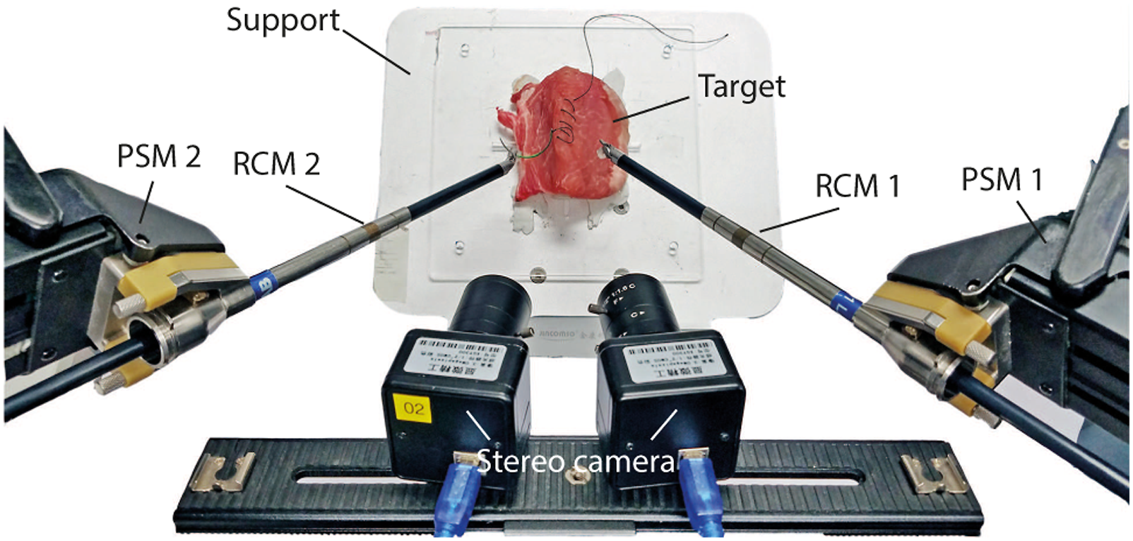
We define the jaw angle to stay 0 during tool-centric actions because the 7
th
is not considered in tool-centric actions. While the instrument enters target-centric actions (with τ > 0 and
Several sensing algorithms are required for providing accurate 3D information to facilitate task completion is introduced in this subsection. The focal lengths of the two cameras are tuned to 30 mm. 5 The image resolution of both cameras are set to 640 × 480 which acquire video streams both at 30 frames per second. The stereo camera has been calibrated in advance (Zhang, 2000) with its backprojection being 0.1582 pixel upon data acquisition of 30 pairs of sample images. The camera-robot transformation has been calibrated using the method based on our previous work (Zhong et al., 2020) to all the engaged PSMs. The performance of our framework is systematically assessed by respectively performing single-arm tasks like debridement and membrane dissection, a dual-arm task like suturing. Task effectiveness in terms of efficiency, success rate and accuracy will be validated.
8.2. Task I: Debridement
The first scenario simulates the surgical tissue debridement procedure, which is designed to illustrate the performance of our framework to automate repetitive reach-and-grasp motions of the robotic instrument to different individual targets. We fabricate a group of L-shape silicone gel blocks to simulate tissue debris. Each block has a bounded 12 mm cube of size which simulates a plumped piece of tissue with a graspable edge, and is attached by a unique fiducial marker of AprilTag (Olson, 2011) with 25h9 tag family for 6-DoF target localization and multi-target identification. The target is online detected and tracked during the task. We apply the MoB to be Mode II (refer to Figure 8) for automating the block reaching with grasping and Mode III for retracting with tissue releasing for debris collection to a plastic plate.
We design a multi-block debridement task to be completed by PSM 1. The blocks are random placed within a rough volume of 50 × 50 mm2 table surface, whose orientation are randomly settled as well. As all the blocks are identical in sizes, their poses are online tracked by using the fiducial markers to generate grasping configurations. Their pick-up sequence is then randomly assigned to avoid adding bias to statistical performance analysis. The releasing pose 
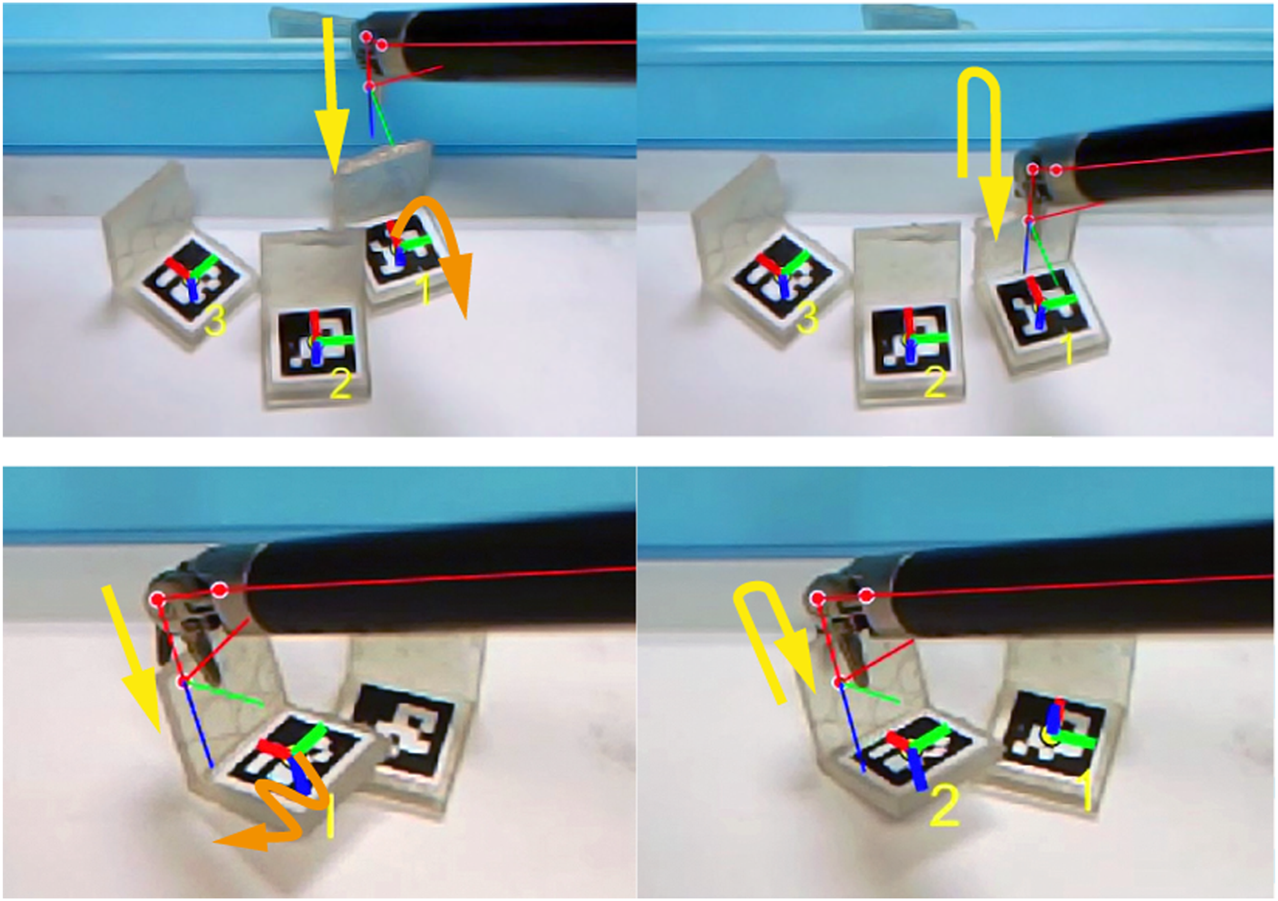
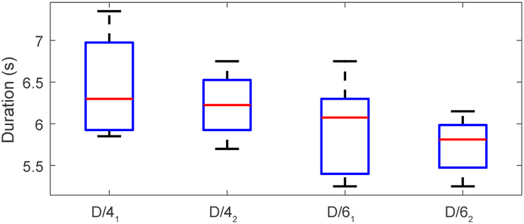
We have conducted ten trials of six-block debridement and ten trials for four blocks. As the main goal of the task is to clear the blocks from their initial positions, we evaluate the quality of this task by assessing the overall success rate of the whole task and the time distribution for each pick-up step. Figure 19 illustrates the snapshots of two trials of six-block trials. The overall success rate for the six-block and the four-block cases are all 90%, that is, both 9 out of 10. Note that for each case, we rearrange the blocks by random placement. Despite different poses, the instrument manages to collect all blocks smoothly. The algorithm could guide the instrument adjacent to the block first and then finalize the contact reaching to achieve a safe grasp thanks to the GVM scheme. It avoids premature tool-target collision during tool-centric action phase which can prevent the tissue from being dislocated or being damaged unexpectedly. This is important as it is normally difficult to track the instant change of tissue’s position shortly before contact due to visual occlusion. We also show in Figure 20 that during the grasping attempt, inaccurate instrument localization might unexpectedly deviate the target from its initial position. Our framework could rapidly react by stating clear from the target first and initiates further adjustment. As long as the target is detectable, the instrument will start another attempt once the tool-target configuration is desirable again. Figure 21 shows the average execution time of each motion step during the task. The median duration for collecting each block is 12.8/11.9 s for four/six block trials. The four-block cases take longer time to complete one debris collection, as the more scattered placement of the blocks leads to longer instrument travel distances. The random block setting does not significant affect the completion time for each attempt, which shows good consistency. Frames of the simulated debridement task using a single robotic instrument. The red and green robot skeleton represents the backprojected layout of the instrument’s current and tissue releasing configuration on the camera image. The Cartesian frame of the instrument’s end-effector (i.e., the tool) and the blocks are also visualized. Target uncertainty during task execution, where the block is unexpectedly deviated to a new position (deviated motion marked in orange arrows) due to premature tool-target collisions. The planned/re-planned tool position is conceptually denoted as yellow arrows. Motion step durations during debridement, where the number 4/6 indicates the number of fragments, and the subscript 1/2 denotes the reaching/collecting motion of the fragment, respectively.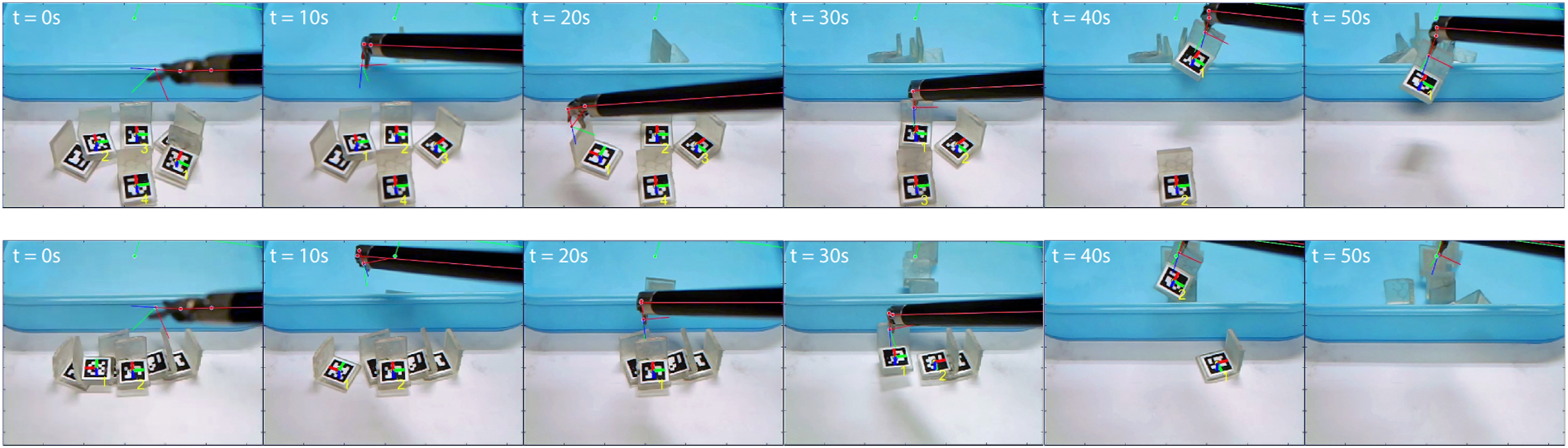
8.3. Task II: Tissue membrane dissection
We next set up an experiment to simulate the dissection task to a tissue membrane, which is a typically demanded in surgeries involving organ removal like laparoscopic cholecystectomy (Reynolds Jr, 2001). The task includes highly repetitive cutting sub-steps in order to dissect the superficial layer of the tissue via a prescribed trajectory. We use a soft handkerchief paper with average thickness of 1 mm as a phantom tissue layer. The layer is fixed by a static support which keeps the tension of the surface to simulate the connectivity of the target to surrounding tissues and to reduce tissue deformation. PSM2 is used to perform the task using the Potts Scissors instrument to provide cutting shear force to the target. The tissue is of size 90 mm * 80 mm, and the dissection path on the tissue is marked by a red line that goes across the layer surface. We set two types of path, one starts from the short edge and ends at the opposite one (with total length of 90 mm), and the other spans diagonally to the midpoint of the long edge (with totally length of around 60 mm). The 3D positions of the path endpoints are detected first using the stereo camera and then are used to interpolate the path profile by comparing the backprojection error with respect to the observed one. Finally, and the interval distance d c to between consecutive cutting steps is computed to determine the cutting points. For empirical experiences, we select such distance to be d c = 3 mm, which indicates a 30-time cutting motion sequence for a 90 mm path and 20 cuts for 60 mm path.
We have conducted five consecutive trials for this task. Three trials are set We use Mode III to perform the dissection procedure (could be also solved by Mode IV but slightly slower) and the clamping motion of the scissors is done after settling the manipulation. The setting of d
c
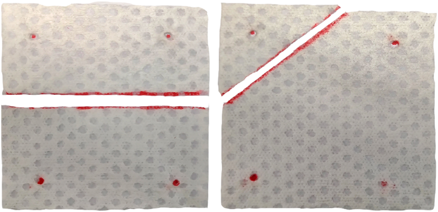
is set smaller than the length of the scissors (around 9 mm) allows a backward shifting before proceeding to the next step to avoid the tissue-tool adhesivity to after each cutting. During the procedure, the instrument automatically plans and dissects the phantom layer progressively through repetitive cutting steps and separates the layer in half via the labelled paths. Figure 22 shows the snapshots of the recorded clips of the real-time automated dissection process using a single instrument. The robot successfully completes four out of five trials with the overall success rate thus being 80%. The failure case is caused by tool-tissue entanglement with uncontrollable path deviation. The average duration for executing the whole task is 81.1 ± 1.2 s and 54.3 ± 0.9 s for the 90 mm case and 50 mm case, respectively. The time cost for performing each single cutting step is 3.9 ± 0.3 s. The dissected layout of the phantom tissue layers are shown in Figure 23. Upon manual measurement, the maximum lateral deviation from the prescribed linear path is around 1.5 mm for both 50 mm and 90 mm case (we assume the highest resolution for measurement is 0.5 mm as the smallest scale of the used ruler is 1 mm). Frames of automated phantom layer dissection procedures. The first and second rows indicate the 90 mm case and 60 mm case, respectively, through paths with different directions. Demonstration so the dissected phantom layers placed on the table with the prescribed cutting paths in red lines, and the fixation points to the support marked in red dots.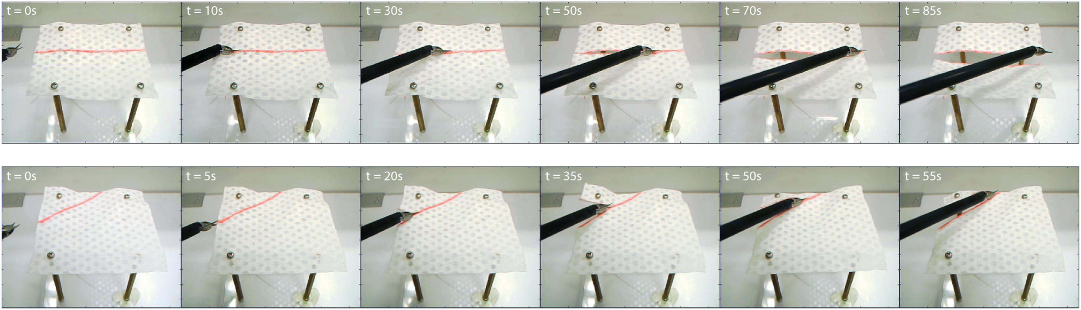
8.4. Task III: Wound suturing
We finally conduct autonomous dual-arm multi-throw wound suturing as a comprehensive evaluation of our framework to perform complicated tasks. The task appears in most surgical interventions, where a suturing needle is guided through wound edges for tissue approximation and wound closure. The guideline is characterized by our framework in Figure 8 into seven individual steps for each throw.
8.4.1. Scenario setting
To construct the setup, we use two PSMs which are both mounted with LNDs as the surgical tools. To regulate the in-hand needle grasping position, we adopt the work in Sen et al. (2016) that uses 3D-printed PVS needle holder mounted along the jaws to enhance needle manipulation accuracy. The stereo camera is placed between the two distal tools as a three-point invasion in typical laparoscopy (Horgan and Vanuno, 2001).
Two types of tissues are used in our experiments. The first type is the artificial soft tissue that consists of two layers, the outer layer to simulate tissue skin and the inner layer for the dermal structure. Both layers are made from synthetic gel. We also prepare a piece of porcine tissue by using two separate parts to create a lumped wound for ease of selecting needle insertion orientation. The tissues are both fixed on a support to prevent unnecessary movements. The positions of the wound edges are computed from the user-input wound endpoints via stereo images. In addition, we introduce two parameters: the stitching width d w that denotes the distance between the needle’s entry and exit point on the tissue, and the throw distance d t that denotes the (ideal) parallel distance of the suture between consecutive throws. Without loss of generality, we set d w = 10 mm and d t = 5 mm as a resembling scale setting in standard robot-assisted surgical training procedures (Garcia-Ruiz et al., 1998).
8.4.2. Single-throw suturing
We first show the capability of our framework to complete a single-throw pipeline in suturing. Figure 24 shows the snapshots of individual motion steps of a single-throw pipeline on the artificial tissue. The needle’s insertion and exiting point on the tissue is directly assigned by user input that yields the preset d
w
and d
t
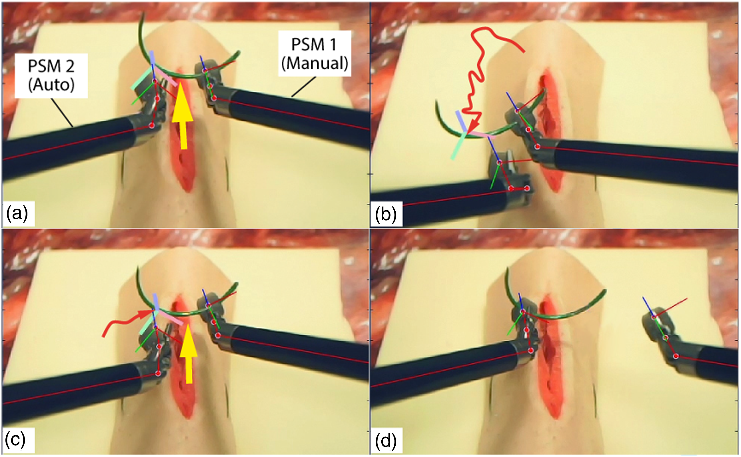
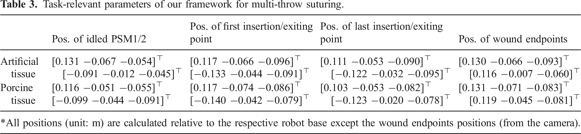
. The instruments start from preset idle configurations which are cleared from the target tissue. The manipulation in each step is converged to the goal configuration with || Step illustration of a single-throw suturing during task automation. From left to right: 1) idle (the start of a throw); 2) needle (pre-entry) targeting; 3) needle insertion; 4) needle regrasping; 5) needle exiting; 6) suture pulling; 7) needle hand-off; and 8) resetting (for starting the next throw). When PSM1 is manually controlled by a user (with the shaky trajectory in red arrows), PSM2 stably tracks and makes contact attempt (in yellow arrow) when the tool-target alignment becomes desirable. Task-relevant parameters of our framework for multi-throw suturing.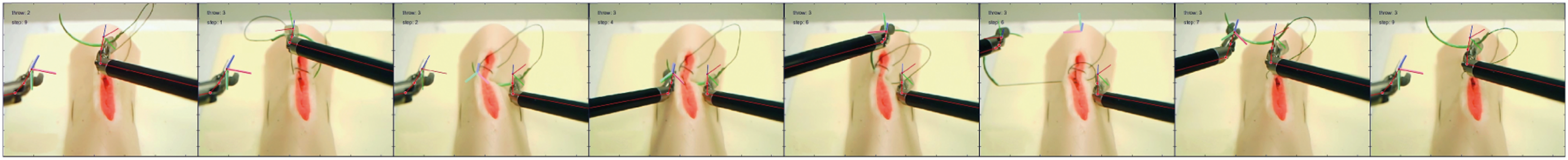
8.4.3. Multi-throw suturing
We define a five-throw suturing task for artificial tissue and a four-throw suturing task on porcine tissue to comprehensively evaluate the task-level applicability of our framework. The suturing will be performed using single-continuous suture pattern, which is a common and efficient type of suturing technique in RAMIS. We do not include knot tying at the end of suturing due to the complexity of detecting the suture’s 3D topology, which is not the main goal of this work. The needle’s insertion/exiting positions are computed based on two virtual 3D markers (named as the “wound positioners”) manually input by the users via stereo images prior to the start of the task. The needle insertion orientation is computable once the insertion and exiting point is known (Pedram et al., 2017). Note that we select d t as 8 mm for the porcine tissue to evaluate task performance under different settings. The moving distance of the suture pulling step is computed based on its consumed length of suture in each throw, which is generically given as 14 mm measured from teleoperation based on the assigned d w and d t . Trials on each type of tissue are conducted continuously to maintain identical setting throughout the experiments.
We perform ten trials for each type of tissue, respectively, under identical setting. The task-level assessment include task success rate to evaluate reliability, duration of a single throw and the entire task for in-process performance, and resultant suture pattern accuracy for task quality. Figure 26 illustrates the frames of task execution process on both the artificial and porcine tissue viewing from the sensing (left) camera. The task is defined as “successful” only if the suture passes through both edges of the wound for enough times without user interference. The overall success rate of performing five-throw suturing is 80% on the artificial tissue (i.e., 8/10) and 70% on the porcine tissue (i.e., 7/10). The failure cases are either subject to needle-suture entanglement or missing the exiting point during insertion. It could be further elevated to 90% (i.e., 9/10) for both the artificial tissue and porcine tissue suturing, respectively, if manual suture arrangement is provided during the task. Note that the above data is calculated by directly regarding a task as a failed trial once any step failure occurs during the process. For step-wise failure, we manually halt the task once a failed step occurs and rearrange the needle/suture accordingly, and then let the robot proceed to the rest of the task to compute the accumulative number of step failure. In this case, a total of 5 motion failures during 10 trials of five-throw suturing (or among the totally 640 motion steps), which indicates 0.8% of motion failure. Frames of dual-arm wound suturing using our framework on the artificial tissue (first row) and the porcine tissue (second row). Each image is captured at the same moment in the step (during needle targeting in the first row and during needle insertion in the next row).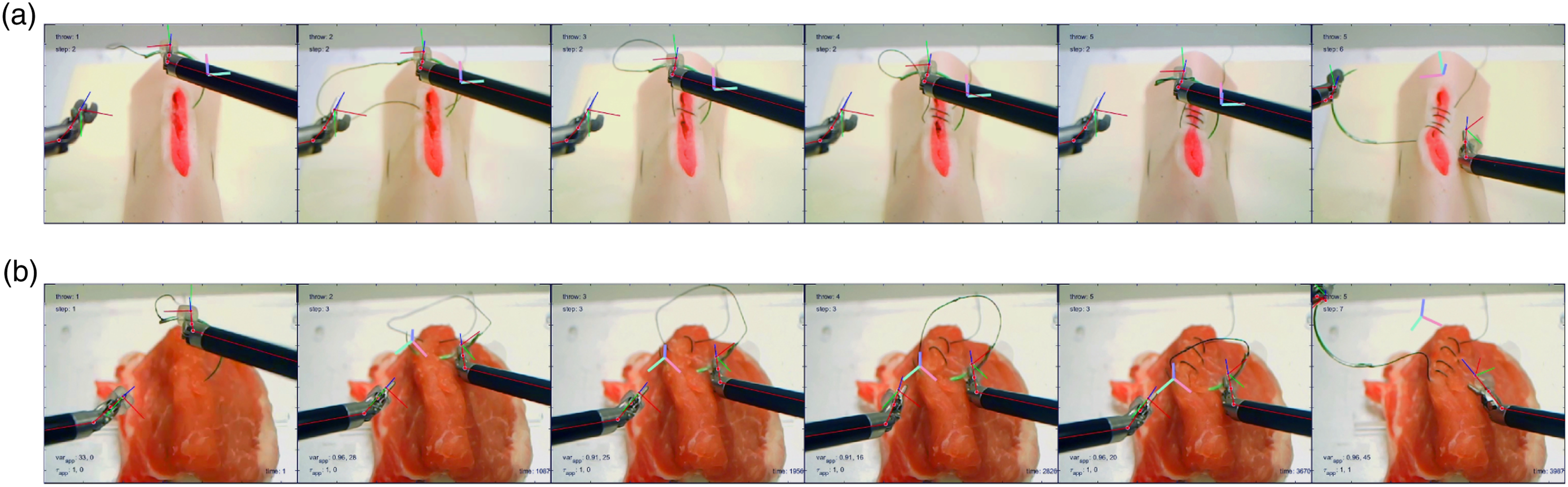
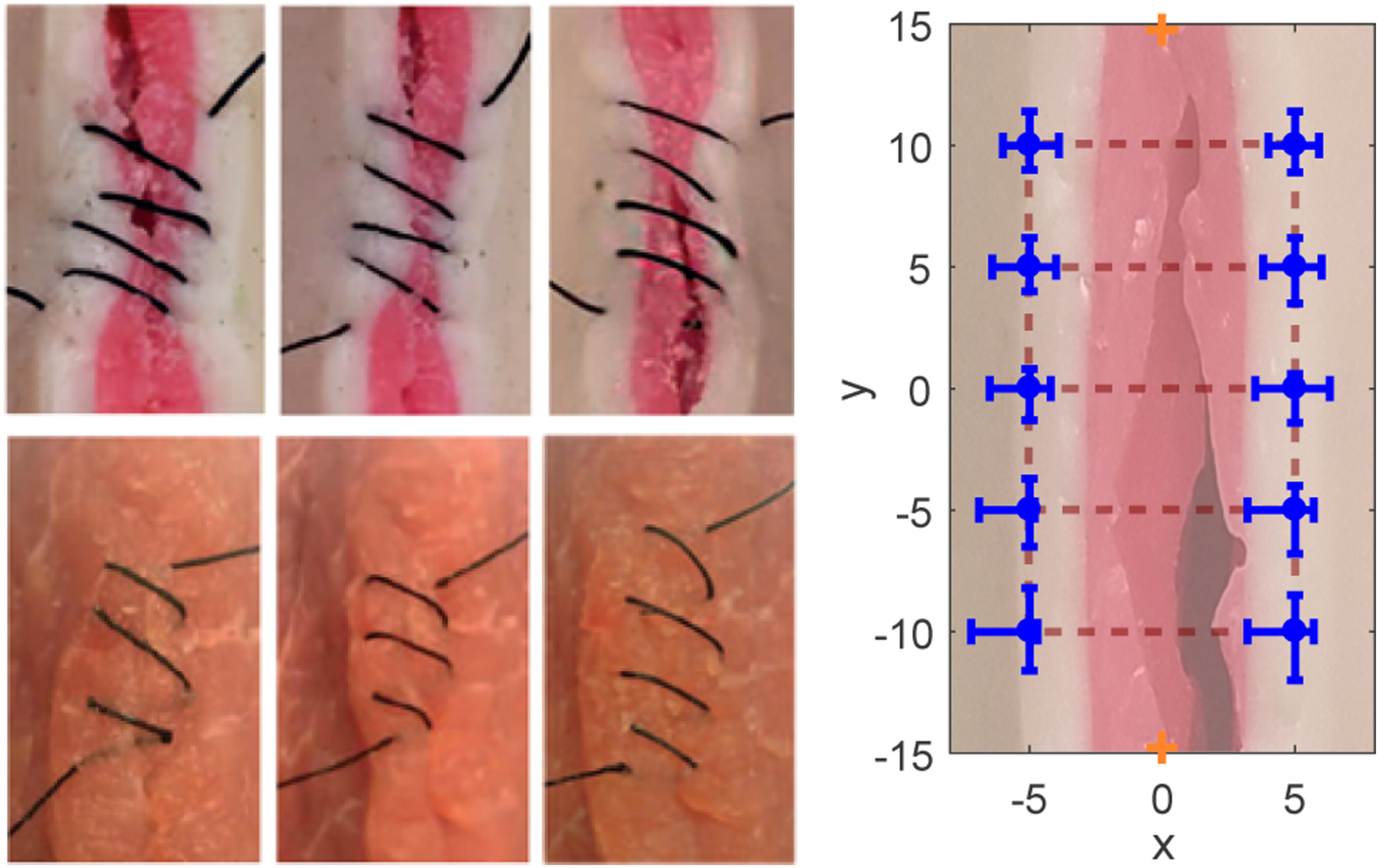
Suturing the porcine tissue owns lower success rate, as the tissue surface might encounter irreversible deformation after many stitches. The trajectories of the two instruments’ distal tool for completing such task are shown in Figure 27. It can be seen that the in-process trajectories maintain good consistency among individual throws without unpredictable movements. Figure 28 demonstrates the suturing accuracy on the artificial tissue.
6
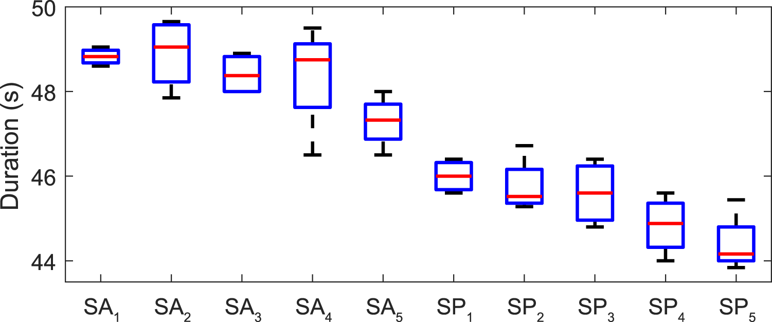
Figure 29 shows the time cost for completing individual throws in the task. The average time of performing one throw is 48.3 ± 1.4 s and 45.1 ± 1.0 s for artificial/porcine tissue, with the time variation percentage for being only 2.9% and 2.2%, respectively, which shows good step-level consistency. The average time cost for completing each throw gradually decreases (shown in Figure 29), as the decreased residual suture length lowers the travel distance for suture pulling. Furthermore, we characterize the outcome quality by manually measuring the deviation of the insertion/exiting position accuracy. The total average accuracy is 1.7 ± 1.1 mm, with the maximum 2.0 mm of wound deviation as the number of throws increases due to the irreversible deformation after several trials. The deformation remains limited influence on suturing accuracy, and is regarded tolerable unless it causes misplacement of the needle during insertion (which is directly regarded as failure). Trajectories of the two instruments during the five-throw suturing task, where the red/yellow/green/blue/purple indicates the trajectories from 1st to 5th throw, respectively. The suture pattern on along the tissue wound edges after five-throw suturing (left-upper three: results on artificial tissue; left-bottom three: results on porcine tissue), and the manually measured suturing accuracy on the insertion/exiting positions (the right figure). Duration required for each throw for suturing an artificial tissue and a porcine tissue, respectively. The gradual descent appears via consecutive throws in attributed to the shorter residual length of suture and thus shorter suture pulling distance under saturated tool velocity.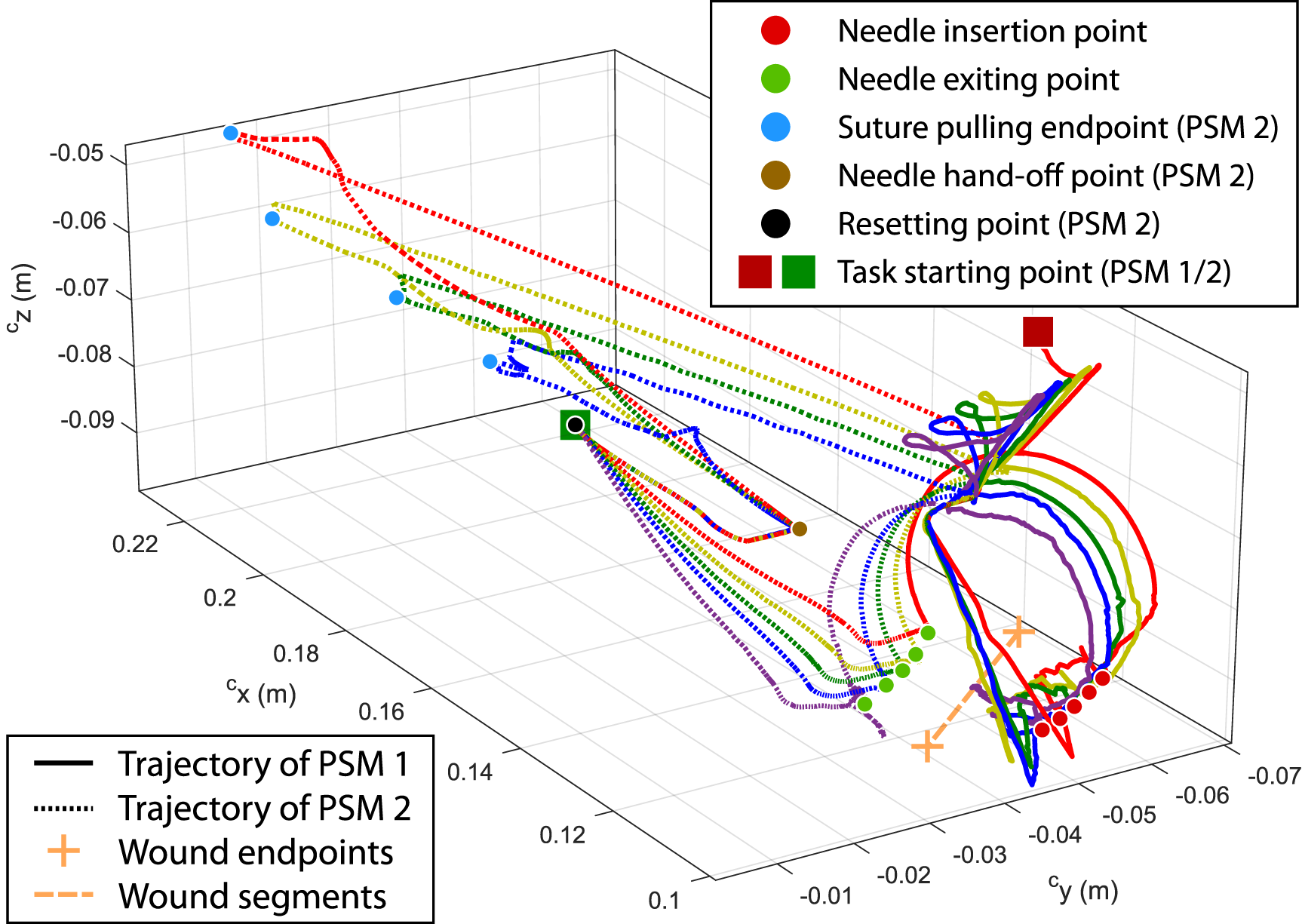
8.5. Overall assessment
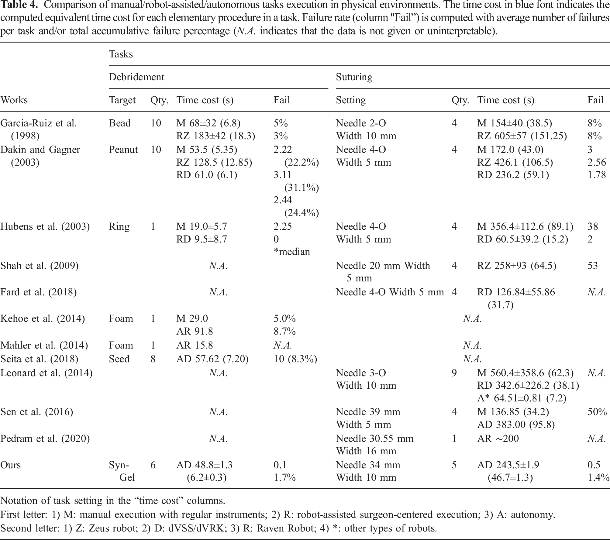
In this subsection, we validate the task-level performance of our framework by comparing with existing works reporting either manual task operations by novice surgeons, or state-of-the-art automation approaches. We focus on aspects including the time cost, the step/task failure, and number of individual trials in each task which are all metrics that reflect the task execution quality and consistency during performance assessment (Martin et al., 1997). The existing works which aim to automate the identical tasks (e.g., continuous debridement and suturing) using the standard guidelines with articulated surgical robots will be especially selected and compared to ours as side-by-side analysis. Note that we are unable to provide identical task-relevant parameter settings for performance comparison, as many works do not provide detailed parameter settings. The comparison will be conducted based on their best reported results as well.
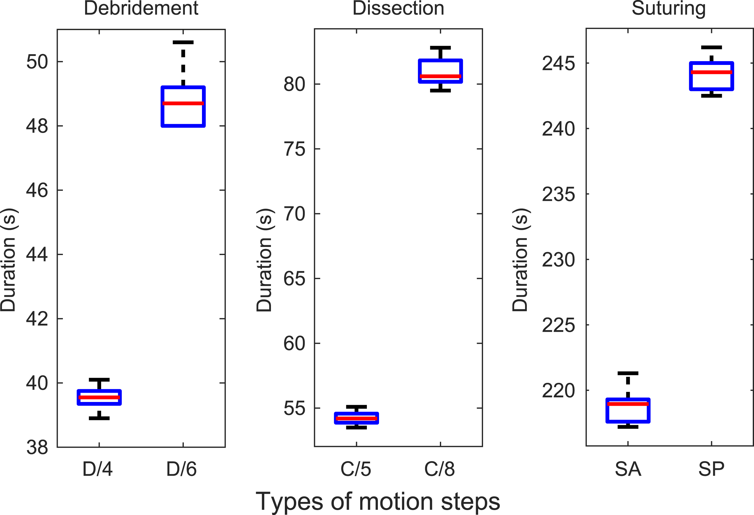
We first summarize the duration performance from the above experiments into time cost for completing each task-relevant motion step (results shown in Figure 30. The time cost for completing the different task-relevant motions under different setups are shown in Figure 31. We calculate the variation percentage of the duration for each step in terms of the average time cost is 3.3%/4.5% for the 4-/6-block debridement, 3.7%/3.7% for the 5/8 mm dissection procedure, and 1.8%/1.4% for the four-/five-throw suturing on the artificial/porcine tissue, respectively. They indicate good consistency of robot’s planning and control performance under different setups. As there are current no existing works that automate different surgical tasks, the performance could be used as a benchmark for future works to refer to for multi-task automation. Comparison of duration of individual motion steps in different surgical tasks (D indicates debridement task, C indicates dissection task, S indicates suturing task). Time consistency of completing task-relevant motions with different settings (D/4 and D/6 denote 4-/6-block debridement, C/5 and C/5 denote 50-/80-mm dissection path length, SA and SP denote suturing on artificial/porcine tissue, respectively.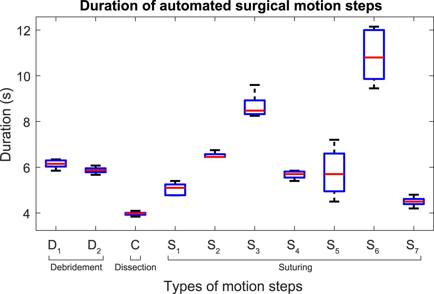
Comparison of manual/robot-assisted/autonomous tasks execution in physical environments. The time cost in blue font indicates the computed equivalent time cost for each elementary procedure in a task. Failure rate (column "Fail”) is computed with average number of failures per task and/or total accumulative failure percentage (N.A. indicates that the data is not given or uninterpretable).
9. Discussions and Conclusions
In this paper, we have presented a generic planning and control framework to automate different types of surgical tasks. The framework systematically addressed both surgery-specific motion safety and task-level characterization, which has been weakly explored. The DS-based controller with SMA globally guarantees the step-level motion stability and trajectory reachability via Lyapunov stability using NSS as system states. The model is efficient, differentiable without iterations, and can solve constrained trajectories without high-dimensional workspace analysis. Meanwhile, the GVM provides adaptive re-planning that guides the robot through constrained path to contact target properly based on on-the-fly situations. The framework was then extended to construct complete pipelines of various surgical tasks including single-instrument tasks like debridement, tissue dissection, and dual-instrument tasks like suturing.
The proposed framework has been validated through simulations for performance study, and then through experimental study on three different surgical tasks (but not limited to). The performance comparison shows that our results own good task efficiency, reliability, and performance consistency that outperform manual operations by novice surgeons and state-of-the-art automation algorithms. Despite the absence of detailed parameter settings provided by existing works, our still represents the farthest step of our framework to generically handle continuous multi-step suturing and debridement. The framework could be used when the camera is moving, which commonly appears in surgery, as long as the RCMs of the endoscopic camera and the instrument is not changed. It could potentially be adopted to larger domain of robot-enabled surgical tasks that require more complicated end-effector motions with wristed profiles.
We also address several limitations in this work. We do not actively regulate the online tissue deformation induced by the task motions. This is reported in our suturing experiments that might result in failure of the task due to the inaccurate needle insertion. This could be solved by integrating tension information to formulate the tissue’s dynamic change. One could either directly measure the tool-tissue interaction force (requiring force sensors which could not be achieved by dVRK), or to adopt vision-based tracking of tissue deformation using trackable surface features (mostly individual points). The deformation relative to its resting state could be online monitored to estimate the (relative) tension. Excessive deviations could be modelled as repellent factors and avoided by intermediate poses in goal-varying manipulation. Meanwhile, the camera-robot transformation is pre-calculated using efficient autonomous calibration approach in Zhong et al. (2020). It is not updated during the task, where the leading positioning error of the instrument (even though not significant) is not online refined, but currently being capable of obtaining good task success rate. Once it could be updated to minimize the residual positioning error, the motion accuracy apart from the planning and control framework could be further improved, which is currently our ongoing work.
There are several directions extendable from this work. The task-level performance and assessment results could be used as a benchmark to be addressed by future approaches under such setting. We are also developing learning-based perception algorithms to localize target surgical areas such that our framework could be applied to complex surgical environment that targets clinical applications. Moreover, we would like to explore active tissue deformation regulation during task automation to further improve task-level reliability under dynamic/uncertain physical situations.
Supplemental Material
Footnotes
Acknowledgements
We thank Mr. Dickson Chun Fung Li and Ms. Yaqing Wang for their assistance in the setup of physical experiments.
Declaration of conflicting interests
The author(s) declared no potential conflicts of interest with respect to the research, authorship, and/or publication of this article.
Funding
The author(s) disclosed receipt of the following financial support for the research, authorship, and/or publication of this article: This work is supported in part by the Shenzhen Portion of Shenzhen-Hong Kong Science and Technology Innovation Cooperation Zone under HZQB-KCZYB-20200089, in part of the HK RGC under T42-409/18-R and 14202918, in part by the Multi-Scale Medical Robotics Centre, InnoHK, and in part by the VC Fund 4930745 of the CUHK T Stone Robotics Institute.
Supplemental Material
Supplemental material for this article is available online.
Notes
Appendix
References
Supplementary Material
Please find the following supplemental material available below.
For Open Access articles published under a Creative Commons License, all supplemental material carries the same license as the article it is associated with.
For non-Open Access articles published, all supplemental material carries a non-exclusive license, and permission requests for re-use of supplemental material or any part of supplemental material shall be sent directly to the copyright owner as specified in the copyright notice associated with the article.