
Abstract
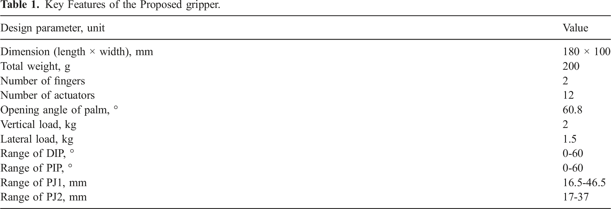
Grasping is a key task for robots to interact with humans and the environment. Soft grippers have been widely studied and some have been applied in industry and daily life. Typical soft grippers face two challenges: lack of stiffness and insufficient adaptability to various objects. Inspired by the human hand, this paper proposes a soft-rigid hybrid pneumatic gripper composed of fingers with soft skin and rigid endoskeletons, and an active palm. Through different combinations of the four joints’ locking states within the rigid endoskeleton, each finger obtains 9 different postures in its inflating state and 13 different postures in its deflating state, endowing the gripper with the capability of adapting to a wider variety of objects. Simultaneously, due to the endoskeletons, the lateral stiffness of the gripper is significantly enhanced (load-to-weight ratio∼7.5 for lateral grasping). We also propose a series of grasping strategies for grasping objects with different sizes and shapes to utilize the versatile configurations of the gripper. Experiments demonstrated that the gripper conformed well to the surfaces of cylindrical and prismatic objects and successfully grasped all tool items and shape items in the Yale–CMU–Berkeley object set.
1. Introduction
Robotic grippers play important roles in daily life (Bullock et al., 2015) and industry (Sivčev et al., 2018). They can replace humans to grasp and manipulate a variety of objects not only in the normal environment (Abondance et al., 2020; Bircher et al., 2021) but also in extreme environments such as the deep sea (Galloway et al., 2016; Phillips et al., 2018; Sinatra et al., 2019; Vogt et al., 2018) and the outer space (Jiang et al., 2017). In addition, robotic grippers can be designed in the form of wearables such as prosthetics (Gu et al., 2021; Laffranchi et al., 2020; Zhao et al., 2016a) to recover amputee’s grasping capability or rehabilitation gloves (Polygerinos et al., 2015; Zhao et al., 2016b) to help the disabled to do rehabilitation training. Developing high-performance robotic grippers can benefit many areas.
From a structural point of view, grippers can be divided into rigid ones and soft ones (Hughes et al., 2016; Shintake et al., 2018). Rigid grippers have been widely used as the end effectors for robotic arms and humanoids. They are usually composed of a series of links and joints and are actuated by motors directly or through cables (Dollar and Howe, 2010; O’Brien et al., 2018; Odhner et al., 2014; Townsend, 2000). They exhibit remarkable stiffness, sufficient grasping force, fast actuation speed, and precise position control. However, most of their components are made from rigid materials like metal or high-density polymer, resulting in large weight, high rigidity, and limited flexibility; therefore, they are insufficiently safe to interact with fragile objects or humans. For example, fruit picking (Elfferich et al., 2022; Tang et al., 2020; Zolfagharian et al., 2022), seafood fishing (Gong et al., 2021; Sinatra et al., 2019; Wu et al., 2022), and the operation of palpation (Burgner-Kahrs et al., 2015; Fang et al., 2021; Xie et al., 2021) all require a gripper to be flexible, safe, and able to handle fragile and vulnerable objects. Therefore, it is beneficial to develop grippers that can naturally interact and cooperate with humans and objects.
Soft grippers made of materials with similar elastic moduli to biological tissues demonstrate potential advantages in safety and adaptability during grasping (Hughes et al., 2016; Langowski et al., 2020; Rus and Tolley, 2015; Shintake et al., 2018). Soft grippers usually rely on stimuli-responsive materials as their actuators, such as electroactive materials (Shian et al., 2015; Shintake et al., 2016), shape memory materials (Kim et al., 2016; Wang and Ahn, 2017), jamming particles (Amend et al., 2012; Brown et al., 2010), fluidic elastomers (pneumatic or hydraulic) (Galloway et al., 2016; Ilievski et al., 2011), etc. Among them, pneumatic grippers use compressed air as the transmission medium and are usually lightweight, clean, and of simple structure (Abondance et al., 2020; Hao et al., 2021; Jiang et al., 2021; Li et al., 2021; Xie et al., 2020). Several pneumatic grippers have been commercialized and put into use in applications such as bakery, medicine, 3C electronics, and others. However, pneumatic grippers face challenges, such as their low stiffness and limited grasping force, which may be unsuitable for heavy-load grasping. In addition, although the soft fingers improved their adaptability to complex geometries when grasping objects with unique shapes, such as objects with sharp edges, it is difficult for pneumatic grippers to adapt to such surface geometry and finally causes grasping failure (Cui et al., 2021; Sachin et al., 2022). Unlike a fully actuated mechanism, soft grippers are usually underactuated and thus can passively adapt to the shape of surfaces in contact with them. The critical problem is that even though a soft structure may have infinite degrees of freedom (DOFs), most DOFs are not actuated and the final shape of the structure is determined by all boundary conditions of the structure, not just the object geometry (Galloway et al., 2013; Glick et al., 2018). Therefore, how to improve soft grippers’ adaptability while maintaining their compliance and passiveness remains a question.
Soft and rigid grippers each have their own strengths and weaknesses. To better enhance the performance of grippers, in recent years, especially with the rapid development of advanced manufacturing methods such as 3D printing (Tawk et al., 2019; Hussain et al., 2020), researchers have been considering combining rigid materials with soft materials, resulting in soft-rigid hybrid grippers, which can be seen as the third category of robotic grippers (Salvietti et al., 2018; Dragusanu et al., 2022a, 2022b). One important motivation for developing a soft-rigid hybrid gripper is that the incorporation of stiffer or stiffness-variation materials/structures can significantly enhance a soft gripper’s stiffness. Guo et al. (2020) introduced a rigid self-locking, stiffness-tuning mechanism to a soft gripper to enhance its stiffness and grabbing stability. Yang et al. (2017) used Shape Memory Polymers with the capability of stiffness variation with thermal energy to actively change the gripper joints’ stiffness. Such grippers are usually actuated slowly and have relatively low energy and time efficiencies. Wei et al. (2016) and Li et al. (2017) both proposed using integrated particle jamming to increase the stiffness of the grippers. The difference between the two works was that the particles of the gripper proposed by Wei et al. (2016) were located on the belly side of the finger, whereas the particles of the gripper proposed by Li et al. (2017) were located on the back of the finger. Zhou et al. (2020) developed a passive particle jamming mechanism into a phalange to adjust the stiffness of the fingertip. Wei et al. (2022) proposed a soft-rigid coupled gripper combining a folded plate mechanism with particle jamming to improve the self-recovery ability of the particles and realized multidirectional grasping. Lotfiani et al. (2020) embedded a 3D-printed rigid skeleton into a soft pneumatic finger to improve the torsional stiffness of the finger. Zhu et al. (2022) effectively improved the grasping force, compliance, and stability of a gripper by proposing a bioinspired multi-modal multi-pose hybrid finger with a rigid actuator on the outside of the soft actuator.
With respect to enhancing the adaptability of a soft gripper, Zhou et al. (2017) designed a novel soft-robotic gripper with three fingers and one passively adaptive palm to enhance its object adaptation. Manti et al. (2015) controlled a single cable’s tensional force to guarantee the adaptability to objects with different shapes during grasping. By adding strain-constraining sleeves to the fingers, Galloway et al. (2013) changed the bending shape of the fingers and improved their adaptability to unique objects. Pagoli et al. (2021) proposed a gripper with reconfigurable fingers by adding a stiff rod to change the bending position of each finger. Hao et al. (2016) investigated the effect of finger lengths on the gripping performance of objects with different sizes. Some other scholars improved the adaptability of the gripper by optimizing the structure of the fingers (Cui et al., 2021; Glick et al., 2018). Teeple et al. (2021), Truby et al. (2019), and Liu et al. (2021) all designed multi-segment fingers to enable different grasping strategies such as pinching and enveloping. It could be concluded from the above work that integrating rigid or stiffness-variable parts can effectively increase the stiffness of a gripper; adopting a multi-joint/multi-segment design in the fingers can potentially improve the adaptability of a soft gripper. In addition, from a bioinspired point of view, human hands with a soft-rigid structure and multi-joint configuration show impeccable dexterity and flexibility and thus can be a role model for gripper design (Deimel and Brock, 2016; Gu et al., 2021; Laffranchi et al., 2020; Puhlmann et al., 2022).
In this article, we propose a pneumatic gripper composed of two fingers and an active palm (Figure 1). For each finger, the soft, airtight skin can bend to different curvatures as its internal pressure changes, and its exact shape is controlled and then locked by the internal multi-joint endoskeleton with four stiffness-variable joints (two revolute joints and two prismatic joints). The unique combination of soft skin and rigid endoskeleton can not only maintain the safety and compliance of the gripper but also enhance its stiffness and adaptability to various geometries of objects being grasped. This 200-g gripper lifted objects weighing up to 2 kg in its vertical direction (load-to-weight ratio: 10) and 1.5 kg in the horizontal direction (load-to-weight ratio: 7.5) Through different combinations of the four joints’ states in the rigid endoskeleton, each finger obtained 9 different postures in its inflating state and 13 different postures in its deflating state, so the gripper possesses the capability of adapting to a much larger variety of objects (cylindrical and prismatic objects with different sizes). To utilize our gripper, we propose and validate an algorithm to calculate the desired postures of each finger to fit objects with different geometries and sizes. Finally, we conduct grasping tests on the Yale–CMU–Berkeley (YCB) object set (Calli et al., 2015). The results demonstrated that this gripper can successfully grasp all tool items and shape items in different postures. Furthermore, we demonstrate that the gripper can manipulate objects (such as rotating a bottle) with a specially designed actuation strategy. Design concept. (a) Anatomy diagram of the human hand with bones, skin, and muscles. (b) Diagram of the proposed gripper with endoskeletons, soft skin, and an active palm. (c) Photo of the gripper not actuated. (d) Photo of the gripper grasping a prismatic object with the endoskeletons locked.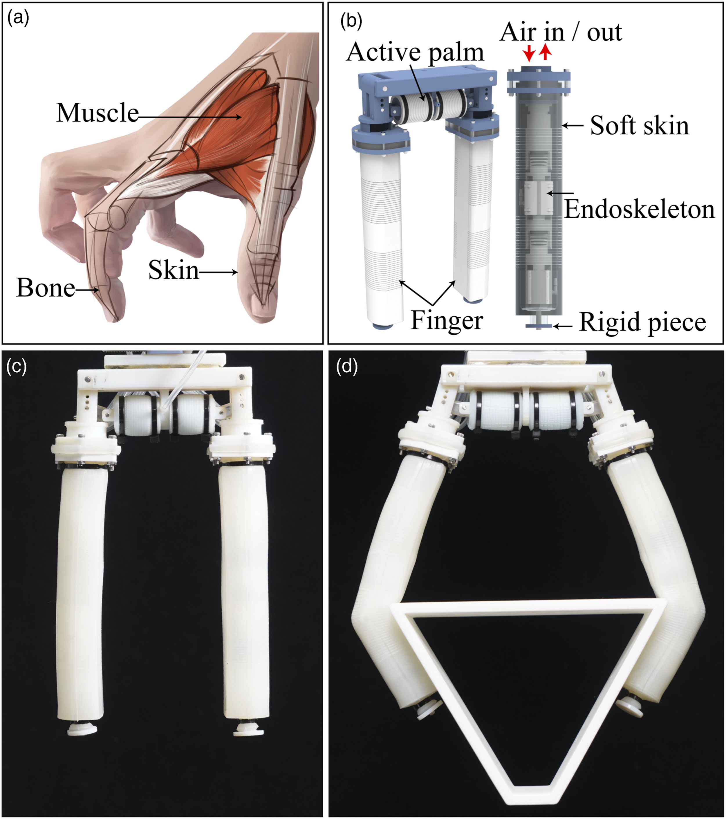
Different from grippers that are precisely controlled with multiple DOFs, which can generate any desired postures, or from underactuated grippers with fewer controlled DOFs and more passive DOFs, which significantly simplify the system, in our work, we combine the advantages of these two strategies and develop a soft-rigid hybrid gripper with active skin (for driving the flexion and extension of the finger) and semi-active endoskeletons (each joint is only with a lock/unlock discrete state to restrict the finger’s motions). This gripper achieves multiple configurations by simply changing the sequential states of endoskeleton joints and successfully grasps various objects in a robust and diverse manner.
The structure of this article is organized as follows. In Section 2, we describe the overall design of the proposed gripper. Then in Section 3, we give the design, analysis, and characterization of the multi-joint endoskeleton. In Section 4, we describe the details of the soft skin and the active palm. In Section 5, we show the characterization of the soft-rigid coupled finger of its posture, stiffness, and force. In Section 6, we describe our proposed strategy to automate the process of grasping using our gripper and give the results of the grasping tests on YCB object set and a preliminary manipulation demonstration with the gripper. A comparison with existing grippers is also presented. Finally, Section 7 summarizes this article.
2. Overall design of the pneumatic gripper
The human hand is a typical soft-rigid hybrid structure consisting of skin, bones, and muscles (Figure 1(a)). The bones provide shape and support for the hand to achieve high-strength grasping and the skin provides a soft buffer between the hand and the object, which can make the hand fit well on the object surface when grasping. The muscles attached between bones drive the fingers to move in different directions with different amplitudes to grasp various objects.
Key Features of the Proposed gripper.
3. Design, analysis, and characterization of the multi-joint endoskeleton
3.1. Structural design and working principle of the endoskeleton
The expected functions of the endoskeleton include (i) enhancing the stiffness of the finger and (ii) facilitating the finger to achieve a variety of grasping postures. As shown in Figure 2(a), we designed the endoskeleton to be a multi-joint mechanism consisting of three phalanges (proximal, middle, and distal) connected by two revolute joints (the proximal interphalangeal joint (PIP) and the distal interphalangeal joint (DIP)). The proximal phalanx is fixed on the palm which will be discussed in later sections. Different from a human finger, the distal phalanx and the middle phalanx each contain a prismatic joint (the prismatic joint 1 (PJ1) and the prismatic joint 2 (PJ2)). Therefore, each endoskeleton possesses four joints in total: PIP, DIP, PJ1, and PJ2. Figure 2(a) shows three states of the endoskeleton: (i) original state, (ii) bending state with PIP and DIP rotated, and (iii) bending and elongation state with PIP and DIP rotated, and PJ1 and PJ2 elongated. Structural design of the endoskeleton. (a) Pictures of the endoskeleton in the initial state, the bending state, and the bending and elongation state. (b) Diagram of the endoskeleton and enlarged diagrams of the two types of locking mechanisms. (c) Working principle of the revolute joint’s locking mechanism and the force diagram of a tooth. (d) Working principle of the prismatic joint’s locking mechanism. (e) The fabrication process of LA1 and LA2 from raw materials. (f) The fabrication process of CA1 and CA2 from raw materials.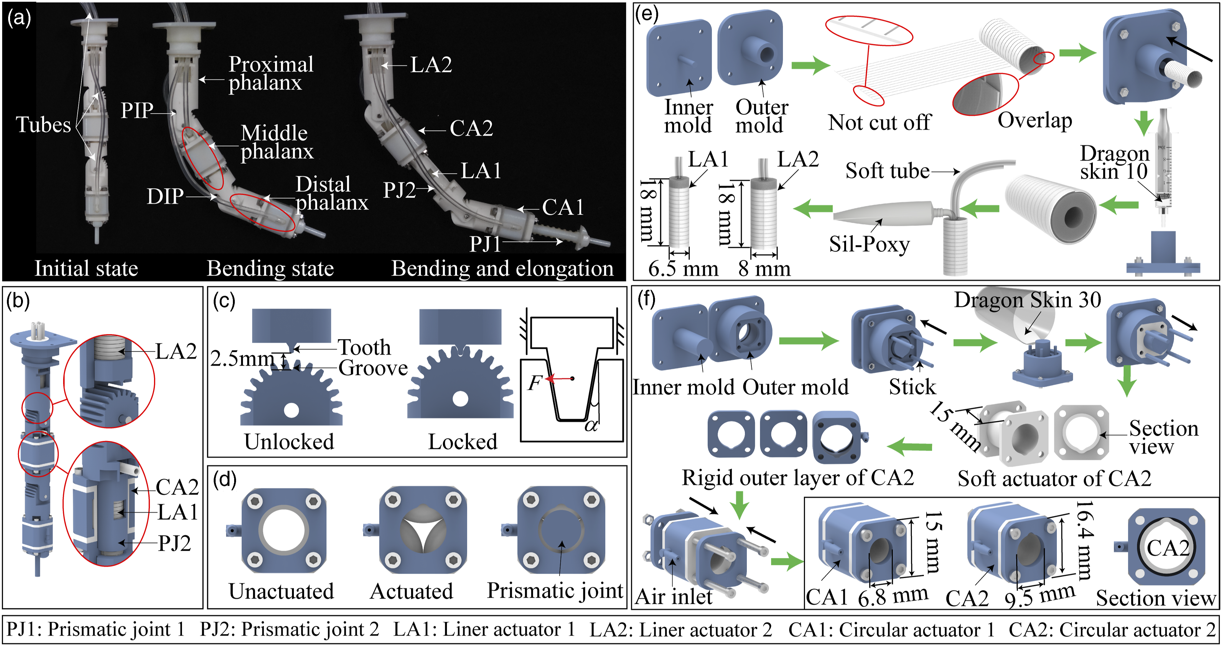
The four joints are not actively driven by actuators and instead they are passive, but they can be locked at any position by specifically-designed mechanisms shown in Figure 2(b). The two revolute joints are locked by a mechanism as shown in Figure 2(c). Take PIP as an example, the locking mechanism contains a tooth-like structure that can slide along the inner wall of the proximal phalanx and is driven by a pneumatic linear actuator (LA2) and a gear-like structure with a circle of grooves (the interval angle between adjacent grooves is 15°) that are fixed on the middle phalanx. LA2 is a fiber-reinforced elastomer actuator embedded into the proximal phalanx. The fabrication process of LA2 (similar for LA1) is shown in Figure 2(e). A similar mechanism controls the DIP and is driven by another pneumatic linear actuator (LA1) embedded within the middle phalanx. When LA1 or LA2 are not actuated, the tooth and the grooves are not in contact, and therefore the joints can rotate freely. When the linear actuator (LA1 or LA2) is inflated, it pushes the tooth into one of the grooves, locking the revolute joint (PIP or DIP). Assume the static coefficient of friction between the tooth and the groove is
The two prismatic joints’ locking mechanisms are different from those of the revolute joints. As seen in Figure 2(b) and (d), there is a pneumatic circular actuator (CA1 and CA2 for PJ1 and PJ2, respectively) between the inner and outer parts of each prismatic joint. When the circular actuator is unactuated, the prismatic joint can slide freely. When the circular actuator is actuated, it pushes inwards, locking the joint. Therefore, the prismatic joints can control their states by inflating or deflating the circular actuators pneumatically. CA1 and CA2 are embedded into the digital phalanx and the middle phalanx, respectively. The fabrication process of CA2 (similar for CA1) is shown in Figure 2(f).
To better illustrate the endoskeleton’s working principles, we have shown the performance of the pneumatic linear actuators (LA1 and LA2) for locking the revolute joints, pneumatic circular actuators (CA1 and CA2) for locking the prismatic joints, the distal phalanx, the middle phalanx, the proximal phalanx, and the entire endoskeleton in Supporting Video S1. All structural parts of the endoskeleton were 3D-printed using acrylic plastics (printed using Objet 30 Pro, Stratasys) or PLA plastics (printed using Raise3D Pro2).
3.2. Characterization of the actuators and the locking mechanisms
To validate that the two types of locking mechanisms could effectively lock the joints, we characterized the actuators’ displacement and force under different pressures. To verify the linear actuators’ capability of pushing the tooth into the groove (Figure 2(c)), we characterized the elongation and pushing force of the two linear actuators (LA1 and LA2). The dimensions of LA1 and LA2 are illustrated in Figure 2(e): the two actuators were of the same lengths but different cross-sectional areas.
The diameters of LA1 and LA2 are different because their installation positions are different. The diameter of LA1 is smaller than LA2 because LA1 is installed in the middle phalanx, which needs to be installed in CA2 to form the linear joint PJ2 (please refer to Figure 2(a)). In contrast, LA2 is installed in the proximal phalanx, which is directly fixed on the palm, and therefore its diameter can be enlarged to generate a larger push force to lock the PIP. Figure 3(a) describes the measured relationship between the elongation of the linear actuators and their inflating pressure. Both actuators generated large axial elongations (14 mm at 240 kPa) and negligible radial expansions. The distance between the tip of the tooth and the root of the groove was 2.5 mm as shown in Figure 2(c). Therefore, the linear actuator’s displacement was far more sufficient to push the tooth into the groove. Characterization of the actuators and the locking mechanisms. (a) Elongation of the liner actuator at different pressures (inset: the initial and inflated states of LA1 at 180 kPa). (b) Pushing force of the linear actuator at different pressure. (c) Clamping force of the circular actuator at different pressures. (d) Experimental setup of the force characterization for LA2 and CA1. (All tests were repeated 3 times and then the means and standard deviations were calculated.)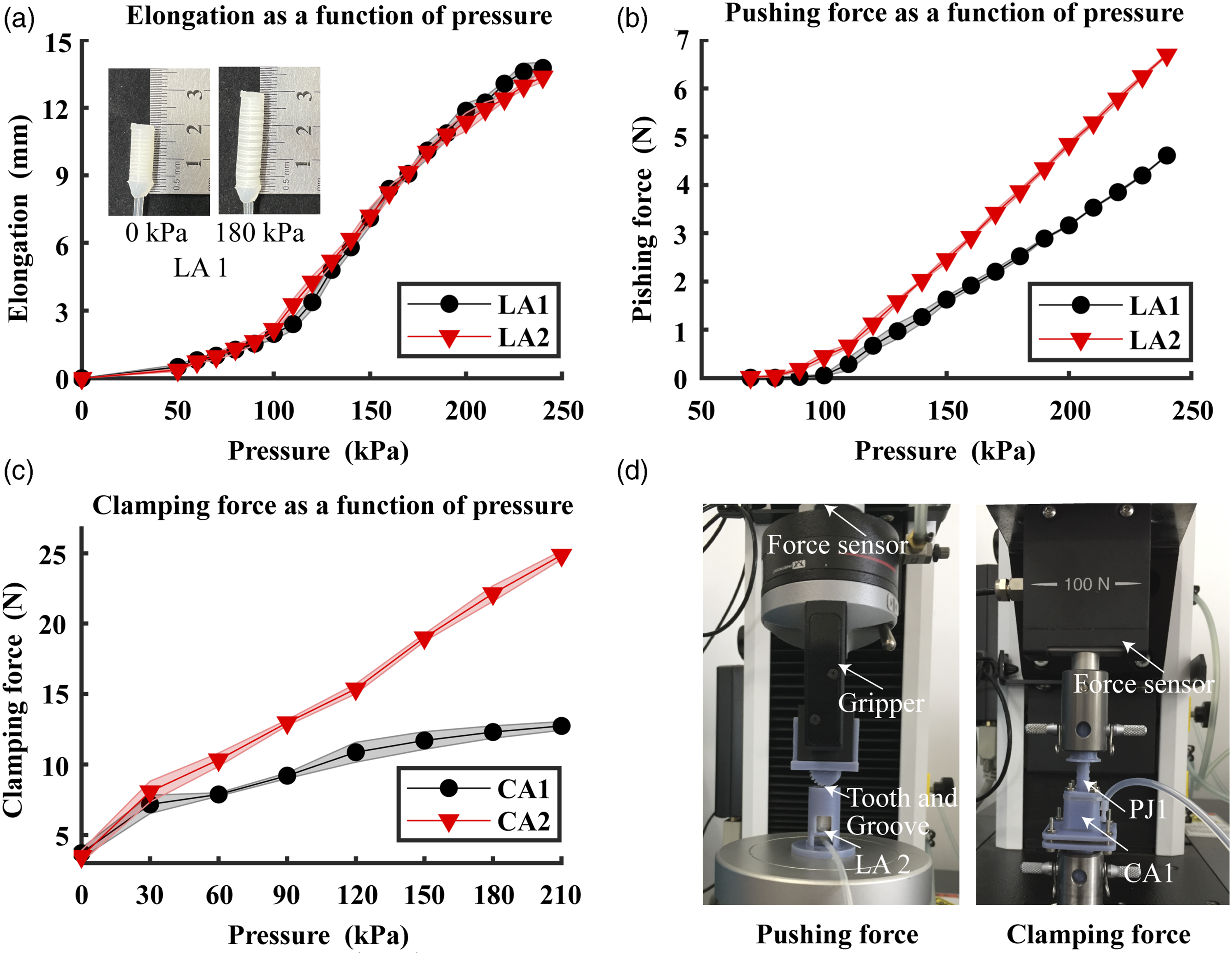
Figure 3(b) describes the relationship between the pushing force of the linear actuators and the inflating pressure. The test was conducted on a standard tensile tester (Instron 3343 Tension & Compression Tester) with a commercial load cell and the measuring setup is shown in Figure 3(d). The actuator was embedded into the locking mechanisms. The pushing force was zero until about 80–90 kPa due to the original distance between the groove and the tooth, and then the force started to increase with pressure. The maximum pushing forces of LA1 and LA2 were 4.6 N and 6.7 N, respectively, due to their different cross-sectional area. The resistive force that the tooth need to overcome during the push-out process was the tooth’s own weight and the frictional force when inserting. Both of the two forces were very small and could be ignored. Therefore, the linear actuator could easily overcome the resistance and push the tooth out. In addition, the pushing force ensured the mechanism’s locking state from the axial direction. As mentioned above, the self-locking characteristics of the mechanism ensured its locking robustness to forces from lateral directions.
Next, we characterized the performance of the locking mechanisms for the prismatic joints. To obtain the maximum clamping force of the circular actuators, we measured the clamping force using a setup as shown in Figure 3(d). The outer part of the prismatic joint was fixed on one fixture of the tensile machine, and the inner part was fixed on the other fixture. Then we inflated the circular actuator to lock the prismatic joint and set the upper fixture to go upwards while we recorded the maximum force as the clamping force. The clamping force was positively related to the pressure (Figure 3(c)). The maximum clamping force of CA1 and CA2 were 12.7 N and 24.9 N, respectively, due to different dimensions (Figure 2(f)). In later experiments, we set the locking pressure of both circular actuators as 180 kPa, and therefore the clamping forces were sufficient to prevent any sliding within the prismatic joints.
3.3. Stiffness of the endoskeleton
To verify that the endoskeleton can enhance the stiffness of the finger, we characterized its loading capacity of the endoskeleton in both the bending direction and the lateral direction, in different joint states. Figure 4(a) and Figure (b) show the loading capacity of the endoskeleton in the bending direction. In Figure 4(a), the two revolute joints were locked at their straight states and the two prismatic joints were locked at their most contracting states. When the maximum load was 400 g, the tip of the endoskeleton was bent to 1.16 cm from the horizontal line. In Figure 4(b), the two revolute joints were locked at their straight states as well, but the two prismatic joints were locked at their most extending state. The tip of the endoskeleton rose to 3.2 cm away from the horizontal line with a 400-g load. This increased deviation indicated a reduced stiffness, and this reduction was mainly due to the increased length of the whole endoskeleton. Figure 4(c) and (d) give the loading capacity of the endoskeleton in its lateral direction. The lateral direction is critical to the gripper’s lateral grasping capability. As we could see from the deviated distances, the lateral stiffness was about half of the bending stiffness. This relatively low stiffness was mainly due to the assembly errors between rigid components that were all 3D-printed. We have also conducted finite element analysis (FEA) in Abaqus for the endoskeleton’s deformation under 400-g load at its tip, as shown in the far-right column in Figure 4. The simulated deformation is smaller than the experimental one, mainly due to that the small assembly gaps were not considered in the FEA. Stiffness of the endoskeleton. (a)-(b) Loading capacity of the endoskeleton in its bending direction. (c)-(d) Lateral loading capacity of the endoskeleton in its lateral direction. The far-right column shows the finite element simulation in Abaqus of the displacement in mm of the endoskeleton under a load of 400 g. (In each subfigure, the first value is the mass of the hanging weight and the second value is the deflection of the fingertip).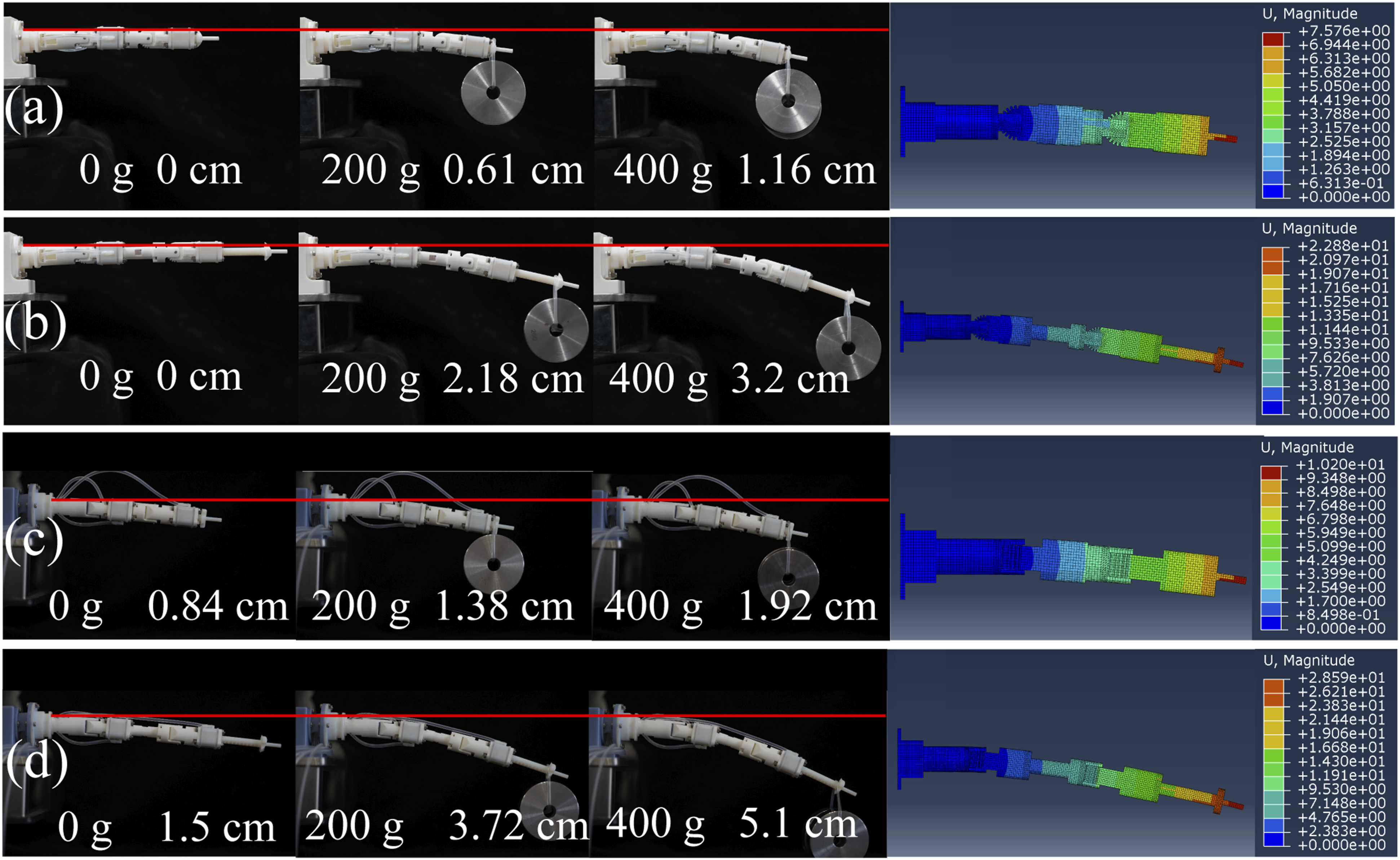
3.4. Kinematic modeling of the endoskeleton
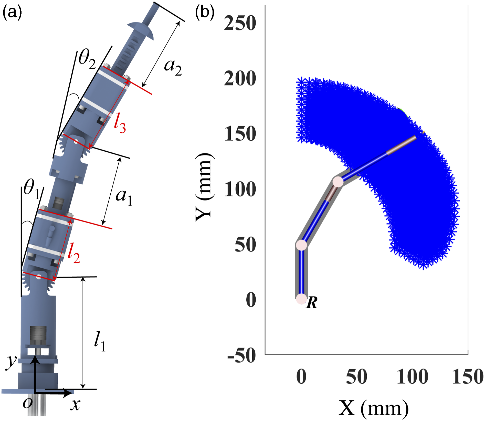
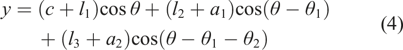
We kinematically modeled the multi-joint endoskeleton. As shown in Figure 5(a), we assume that the distance from the root of the endoskeleton to the PIP is Kinematic analysis of the endoskeleton. (a) Parameters of the endoskeleton. (b) Reachable workspace of the tip.

Take the range of motion for each parameter into consideration (
4. Design of the soft skin and the active palm
4.1. Design and fabrication of the soft skin
The skin of the finger is an important functional part of the finger. It drives the endoskeleton to bend and provides a safe buffer for contacting delicate and fragile objects. For the skin, we designed it as a fabric-reinforced bending elastomer actuator with a large hollow space to house the endoskeleton. As shown in Figure 6(a), the soft skin is made of elastomers with a fiber-limiting layer embedded in, to guide its deformation in certain places. More specifically, we cut circumferential slits in places close to the position of the PIP and DIP of the endoskeleton, which is inspired by human’s finger skin with wrinkles in the joint positions. The fabric layer on the palm side of the finger is continuous with no cut to ensure the actuator always bend to one direction when inflating. When the skin is inflated, the soft skin bends inwards in the “wrinkle” places. Design of the soft skin. (a) Structure and dimension of the skin. (b) Fabrication process of the skin. (c) Assembly of the endoskeleton with the soft skin.
We fabricated the soft skin following steps shown in Figure 6(b). First, we 3D-printed the molds, and we cut slits on a piece of fabric and folded it. Then we assembled the molds, placed the fabric into it, and injected mixed silicone pre-elastomer (Dragon Skin 10, Smooth-On, Inc.) into the assembled mold. After the elastomer was cured (about 7 h), we demolded the cured piece from the mold. Finally, we assembled the endoskeleton into the skin as shown in Figure 6(c).
The endoskeleton was directly inserted into the soft skin and its tip was inserted into the small holes in the tip of the soft skin. Then zip ties were used to seal and connect. To further prevent the zip tie from sliding off, we bonded a small rigid piece at the end of the tip. This rigid piece also assisted the finger to pinch small objects. The inlet of the soft skin and the root of the endoskeleton were connected by two sealing gaskets through screws and nuts. The root of endoskeleton was sealed with silicone to prevent gas leakage. The assembly process and assembled finger can be clearly seen in Supporting Video S2.
4.2. Design of the active palm
In our previous work, we have demonstrated that an active palm-like structure can remarkably expand a gripper’s grasping range of objects (Cui et al., 2021). In this gripper design, we also design an active palm that can adjust the included angle between two facing fingers. The structure of this active palm (Figure 7(a)) consists of two slider-crank-linkage mechanism (three revolute joints and a prismatic joints) and two pneumatic linear actuators for driving the prismatic joints. Each finger is fixed on the second bar. Therefore, the elongation and shortening of the actuator caused by internal pressure change will rotate the finger and change the included angle of the two facing fingers. The actuator (fabricated by Smooth-SilTM 936, Smooth-On, Inc.) was fabricated in a similar way to the linear actuators within the endoskeleton and the soft skin. We also designed three holes on the base of the four-bar mechanism for manually adjusting the finger angle. In Supporting Video S2, we have shown the assembly and performance of the active palm. Design and analysis of the active palm. (a) The structural design and dimensional parameter of the active palm (-base link of the slider-crank linkage, -2nd link, -3rd link, -4th link) (b) Characterization of the rotational angle of the palm mechanism. (All tests were repeated 3 times and then the means and standard deviations were calculated.) (c) Reachable workspace of the tip with the active palm and comparison with that of no palm (red-no palm, blue-with palm, yellow-consider the soft skin’s constraint).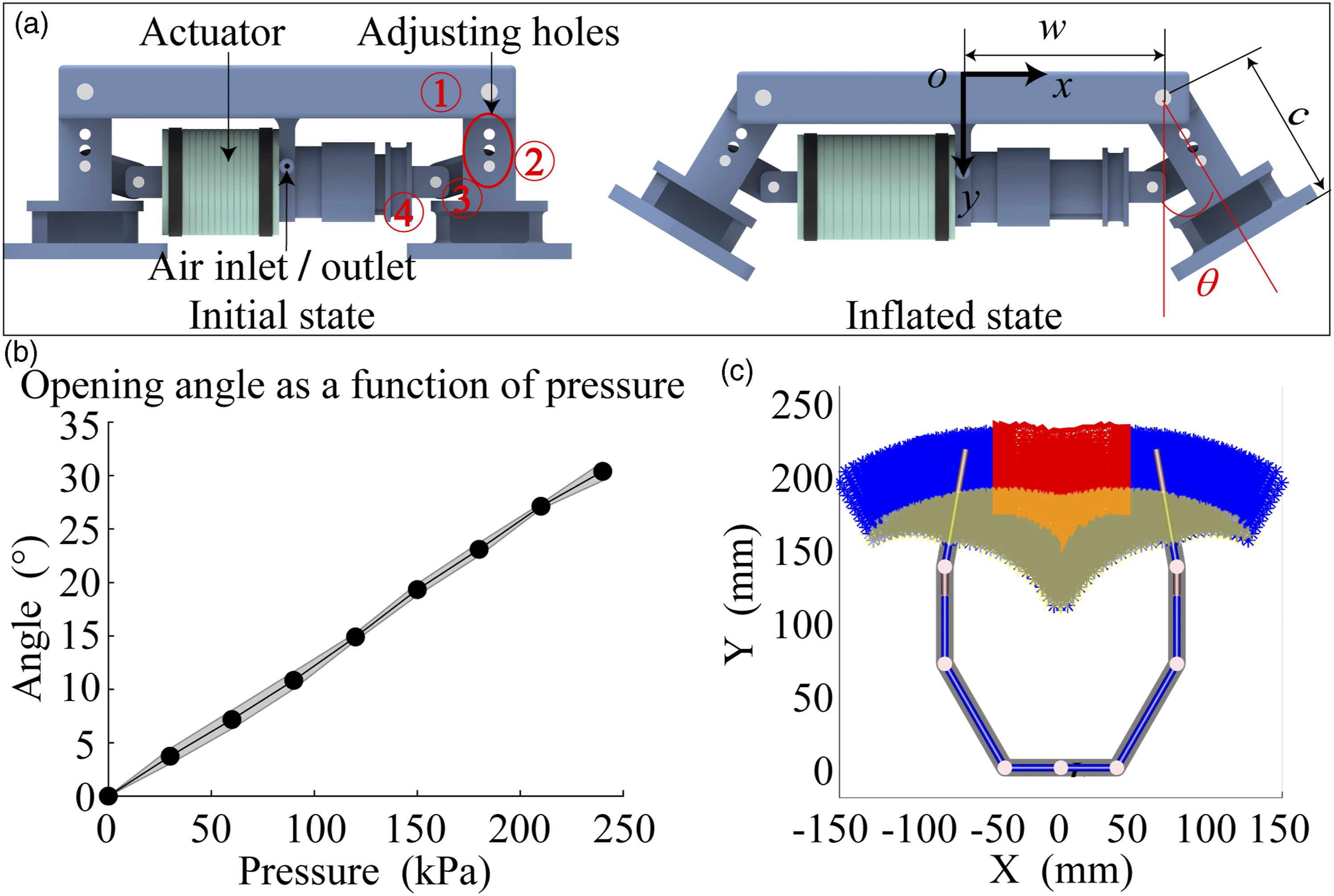
To demonstrate the palm can expand the grasping range of the gripper, we re-calculated the reachable workspace of the endoskeleton with the active palm. Before that, we characterized the palm’s range of motion experimentally. As shown in Figure 7(b), we measured the rotational angle of the second link at rising pressure. At 240 kPa, the rotational angle was 30.4°. With the active palm, the position of endoskeleton tip should be calculated as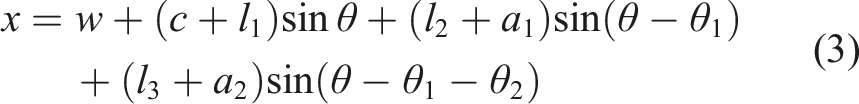
It is worth noting that the gripper’s range of motion is truly influenced by the soft skin. In other words, not all positions could be reached in our calculated workspace. The total elongation of the two prismatic joints should not exceed the allowed elongation determined by the soft skin’s bending angle:
5. Results of the finger with endoskeleton
5.1. Postures of the finger with endoskeleton
Traditional soft, pneumatic fingers often generate uniform curvature under pressurization. When grasping objects with non-uniform curvature, there is always a gap between fingers and objects, and fingers can’t fully adapt to the surface of objects. After integrating the endoskeleton into the skin, by changing the states of multiple joints in a certain pattern, we could achieve different bending configurations of each finger (see Supporting Video S2), and then achieve better adaptability for objects. Here, we experimentally demonstrate such capability.
We first locked/unlocked the four joints (PIP, DIP, PJ1, PJ2) to a certain combination, then inflated the soft skin to 50 kPa, and finally locked all joints to fix the posture and deflated the skin. Figure 8 shows the resulting endoskeleton postures, the inflated finger postures at 50 kPa, and the deflated finger postures in different situations. The endoskeleton had a total of 16 combinations of joint states. We used four binary digits to indicate each state: when the joint was free, we define the state as 1, and when the joint was locked (the locking pressure of all joints is 180 kPa), we defined it as 0. For example, 0011 represents that DIP and PJ1 are free, and PIP and PJ2 are locked. When inflating the soft skin to 50 kPa, there were only nine postures of the finger achievable. The remaining seven postures were unavailable, meaning the finger didn’t bend with pressure and stay straight. These seven invalid postures were due to either both revolute joints were locked simultaneously, or both the prismatic joints were locked simultaneously. When the two revolute joints were locked (0100, 0101, and 0001), it was obvious that the fingers would not bend. Due to the strain-limiting layer, the soft skin could not elongate purely either. When the two prismatic joints were locked (1000, 1010, and 0010), the endoskeleton was not able to extend and thus the soft skin was not able to bend as well as its own neutral plane was on one side of itself. Obviously, the state of 0000 was invalid as well. Endoskeleton postures of the endoskeleton itself, during inflating to 50 kPa and deflating (the four-bit digit indicates the state of PIP, PJ2, DIP, and PJ1, respectively, and 1 represents free and 0 represents locked).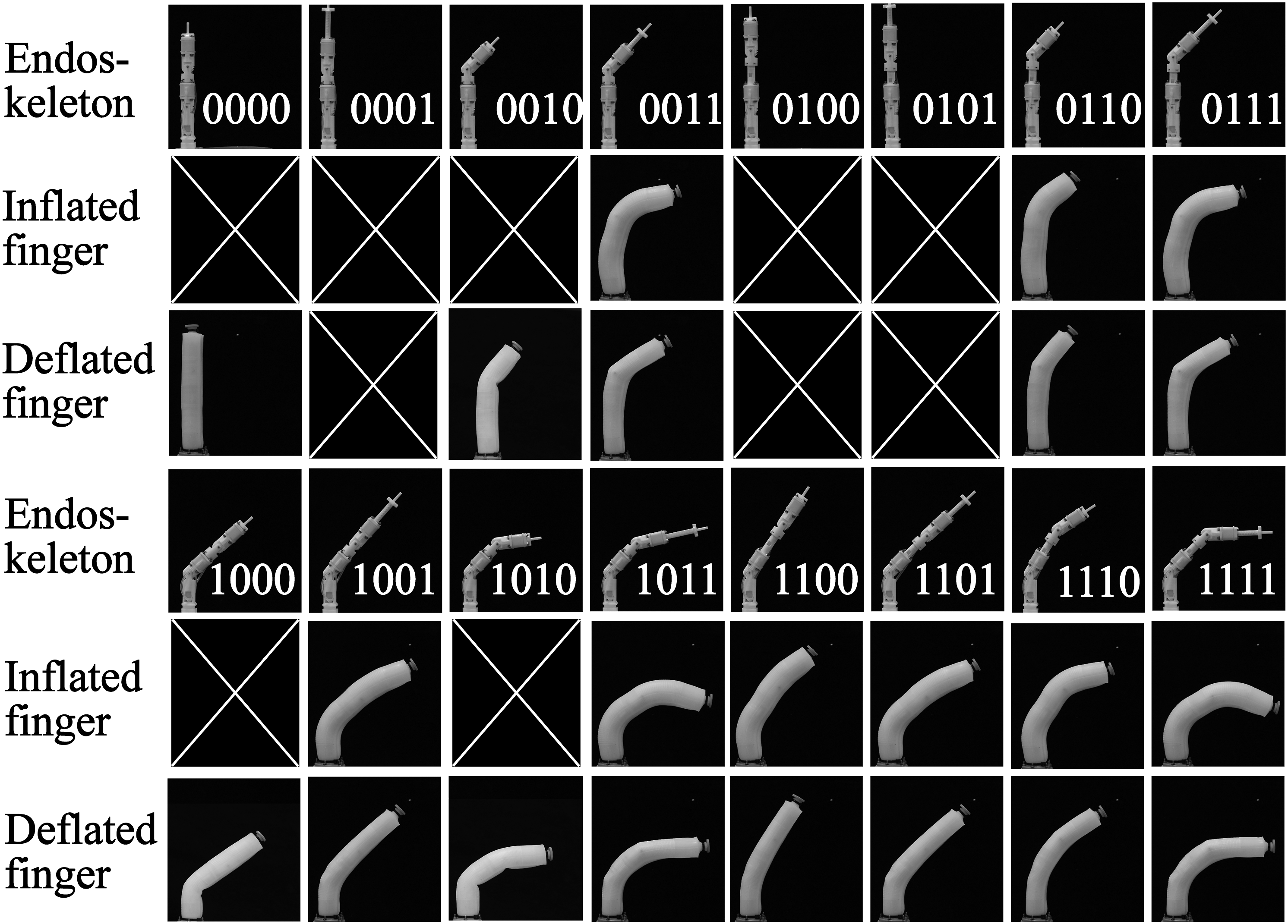
When the finger was deflated, there were 13 postures reachable and 3 unavailable. The same as the inflated states, when the two revolute joints were locked (0100, 0101, and 0001), the fingers would not bend. Yet, for both prismatic joints were locked (1000, 1010, and 0010), even though the center plane of the endoskeleton was not able to extend, the strain-limiting layer could buckle to facilitate bending. The state of 0000 can be seen as reachable in such case.
These deflated postures were always transformed from other inflated postures after deflating the finger. Compared with the inflated finger postures, the inner angles of the deflated finger are sharper. Therefore, when grasping curved objects, the inflated finger is preferred whereas when grasping objects with sharp corners, the deflated finger is preferred.
To explore the finger’s postures under different pressures, we inflated the finger to 30 kPa, 50 kPa, and 70 kPa and then fixed and deflated it (pre-tests showed that all prismatic joints reached their full length at 70 kPa for state “1111” when all joints were set free, and thus we chose 70 kPa as the largest characterization pressure). The postures of the finger are shown in Figure 9. The finger has demonstrated a wider variety of postures under different pressures that we could choose from for more adaptive grasping. Postures of the finger after deflation under different air pressure.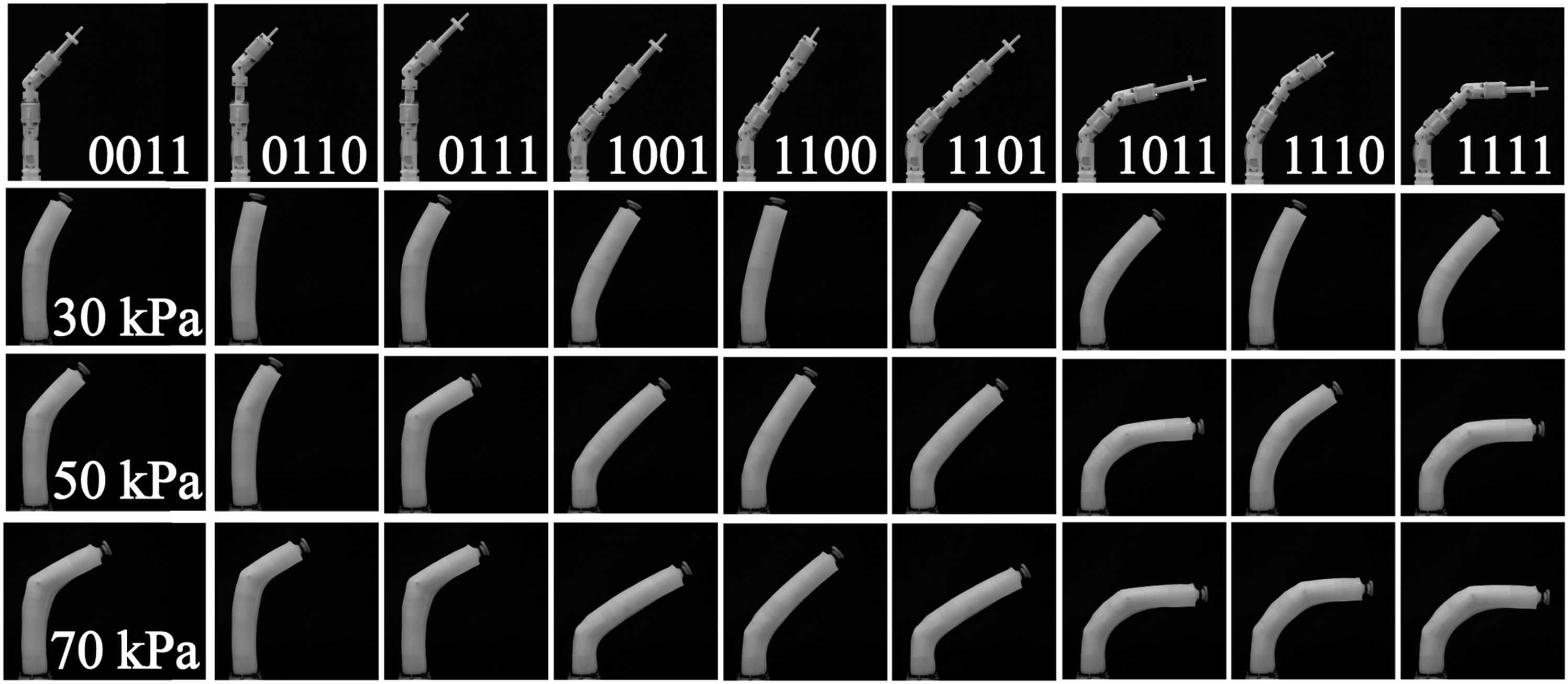
The Required Pressure of the soft Skin for Revolute Joints Bending to a Target Angle in Different Situations.
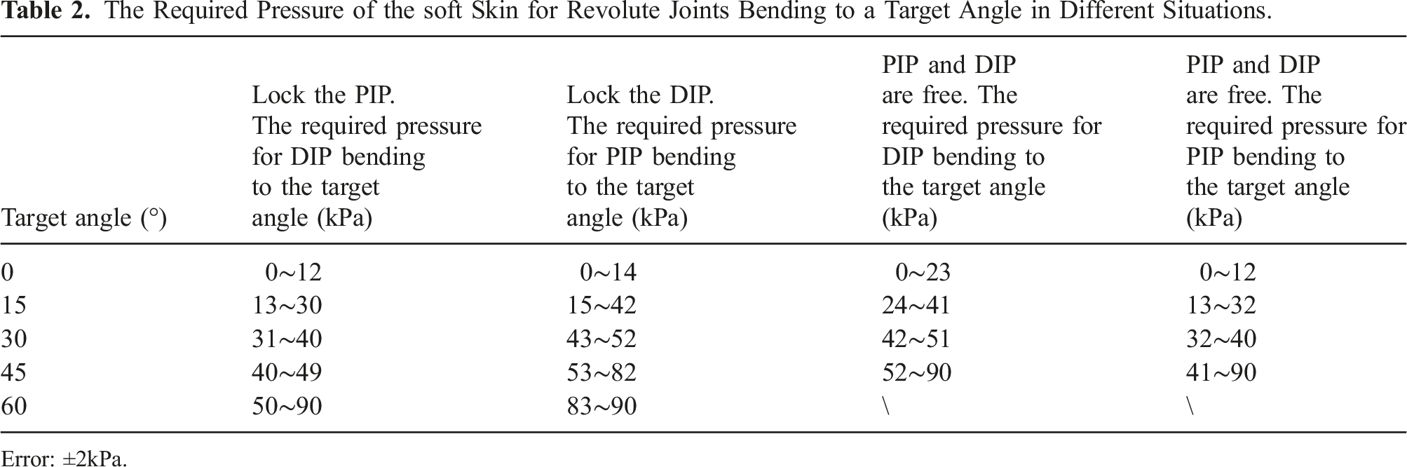
Error: ±2kPa.
5.2. Finger stiffness during joint locking
We verified the multi-joint endoskeleton’s capability of enhancing the finger’s stiffness through locking certain joints. We first set all joints in free states and inflated the soft skin to different pressures (30 kPa, 50 kPa, and 70 kPa), as shown in the first column of Figure 10(a). Then, we set different states of joints and then hung a 500-g weight at the end of the finger to check the finger’s structural stiffness. In column 2, all joints were free. As soon as the weight was applied, the tip of the finger dropped down, indicating a low stiffness in the bending direction. In column 3, the prismatic joints were locked (locking pressures were all set to 180 kPa), and the revolute joints were free. We compared the deflections caused by the weight with those in column 2, and found no obvious difference, indicating the negligible effect of locking the prismatic joints solely. In column 4, the revolute joints were locked (locking pressure were 180 kPa), and the prismatic joints were free. We observed a decrease in the deflections caused by weight, indicating an enhancement of bending stiffness from locking the revolute joints. In column 5, when all joints were locked before hanging the weight, the deflections were similar to those in column 4. From the above exploration, we concluded that the locking of the revolute joints could effectively increase the bending stiffness of the finger whereas the prismatic joints played a smaller role. (a) Finger postures and deflection upon hanging weight at different inflating pressures and with different joint states (R is Revolute, P is Prismatic; in each subfigure, the first value is the deflection of the fingertip and the second value is the calculated stiffness as load/deflection). (b) Comparison of finger deflection after deflation with and without the prismatic joints locked. (c) Grasping capability in vertical and lateral directions of the gripper.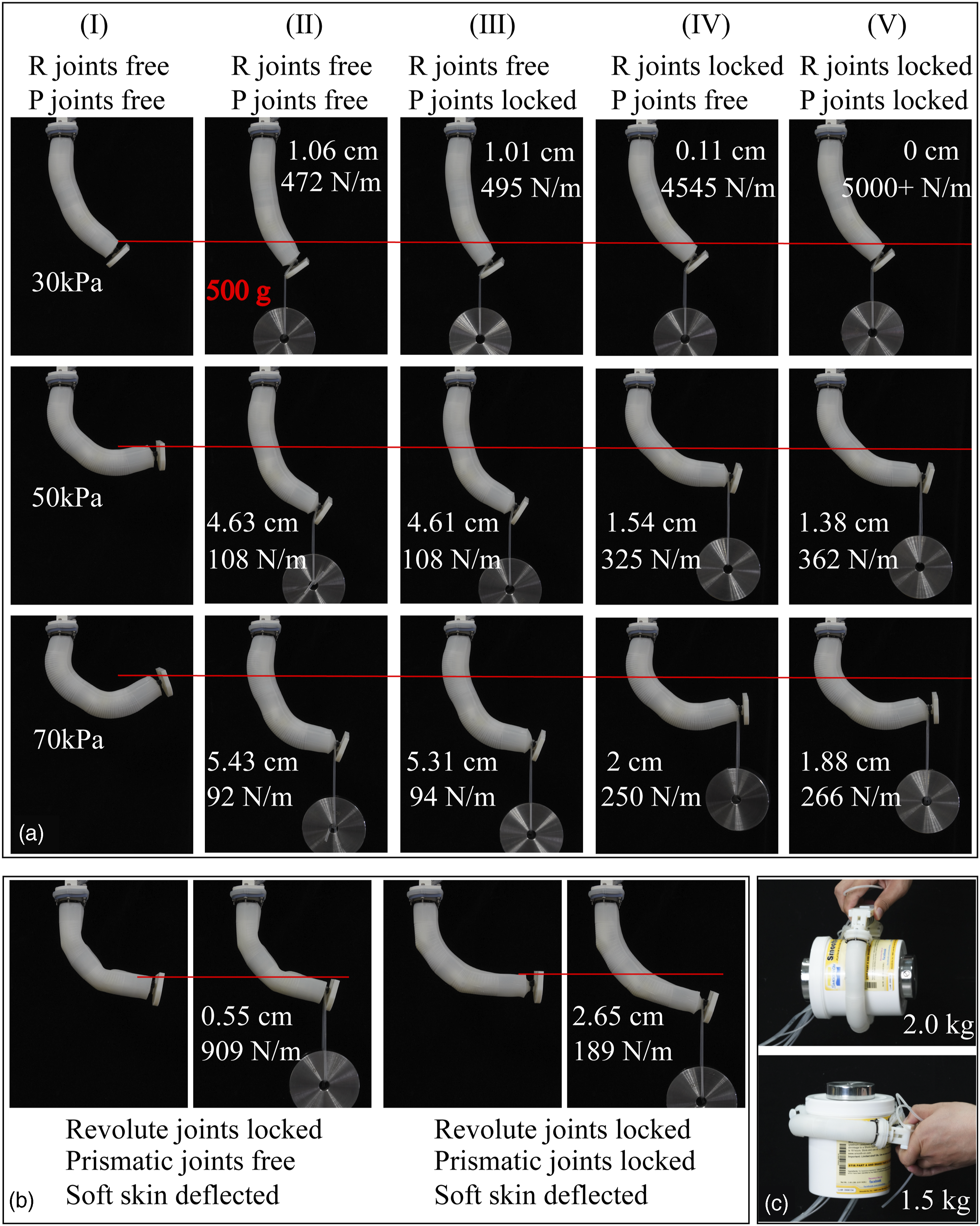
We further checked the prismatic joints’ function by deflating the soft kin for situations in columns 4 and 5 of Figure 10(a). As shown in Figure 10(b), if the prismatic joints were not locked, after deflation, the finger’s length would shrink; whereas if the prismatic joints were locked, the length of the fingers could be maintained. This comparison indicates the function of the prismatic joints as enhancing the axial stiffness of the finger.
The lateral stiffness of the finger depends on the lateral stiffness of the endoskeleton, which we have discussed in earlier sections. We tested the gripper’s vertical and lateral grasping as shown in Figure 10(c). In the vertical direction, the gripper could grasp 2.0 kg weight (load-to-weight ratio ∼10). In the horizontal direction, the gripper can grasp 1.5 kg weight with no obvious deflection of the fingers (load-to-weight ratio ∼7.5).
5.3. Fingertip force
We explored the effect of the endoskeleton on the fingertip force. During the experiments, we set the prismatic joints free all the time and locked both or one of the revolute joints. Then we inflated the soft skin while we recorded the tip forces. From Figure 11, we see that the fingertip force increased with the pressure of the finger whether the revolute joints were locked or not. The fingertip force of the finger with both DIP and PIP unlocked was greater than that of the finger with DIP locked and PIP free, but smaller than that of the finger with DIP free and PIP locked. This difference is due to the position of the center of rotation for the endoskeleton. During inflation, the moment caused by the soft skin’s inflation was in balance with the moment from the tip force. When the PIP was locked and DIP was free, the center of rotation was closest to the tip, which led to a decrease in the distance of the force arm and an increase in fingertip force. The maximum fingertip force was 9 N when the skin’s pressure was 90 kPa. Fingertip force at different pressures and joint states.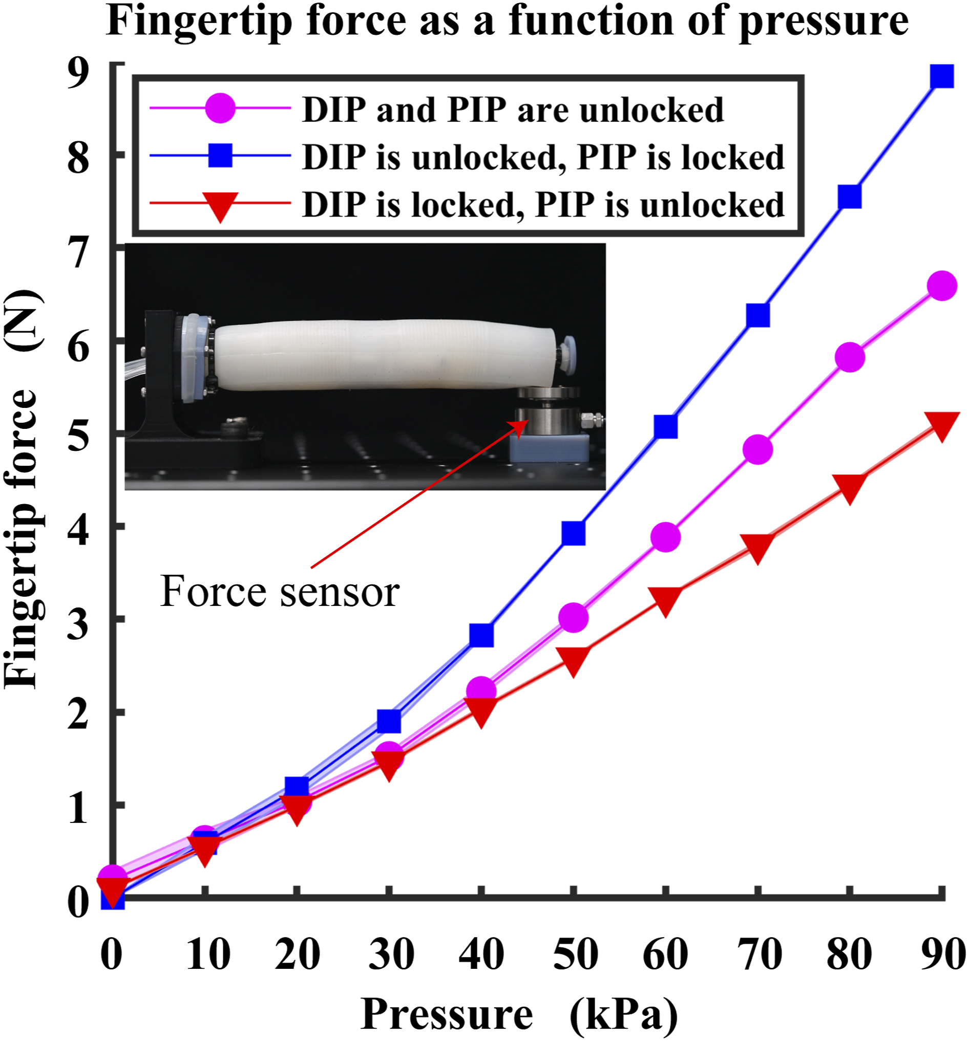
To enhance the finger’s grasping for very thin objects (cards, washers, snails, nuts, etc.) from the table, we designed a special fingernail as shown in Figure 12. This fingernail has a very sharp tip that is suitable for pressing objects with very thin side walls. Gripper with sharp fingernails for picking up thin objects. (a) Utilizing the palm to conduct a pinch grasp. (b) The setup to measure the pinch force. (c) Pinch force with different PIP angles.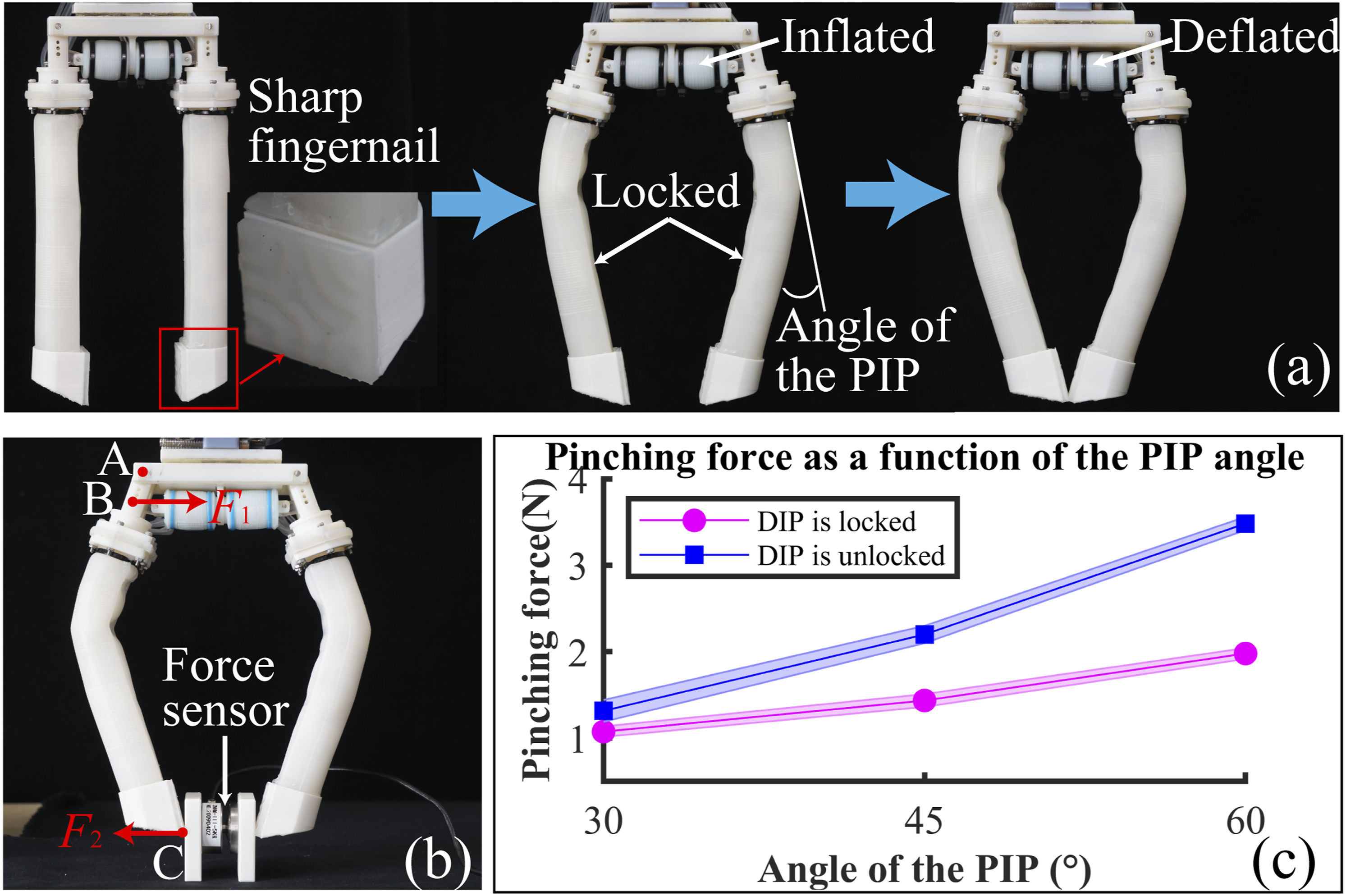
For thin and heavy objects, the gripper can lock the endoskeletons into a special posture, and utilize the palm to perform a pinch grasping, in which case, the fingernail tips move horizontally inwards (Figure 12(a)). We characterized the tip force in such a posture with the setup in Figure 12(b). Result in Figure 12(c) indicates that the tip force is less than 3.5 N, therefore only suitable for pinching light objects. We will validate the performance of grippers with such sharp snails in later sections.
6. Grasping strategy design and grasping experiments with the gripper
6.1. Grasping strategy design for the gripper
In previous sections, we have described the components of our proposed gripper: the palm, the finger, the finger’s soft skin, and the finger’s endoskeleton and built a two-finger gripper (Figure 1(b)). Even though we have demonstrated the versatility of the components (Supporting Video S2), the grasping strategy for this gripper is still a great challenge. The gripper has 5 actuators (LA1, LA2, CA1, CA2, soft skin actuator) and a palm actuator for each finger. To realize the automatic grasping of objects with varying shapes and dimensions, we proposed a set of grasping strategies to map the shape and size of an object to the control commands of the gripper. The basic idea is as follows: first, we decide the desired finger posture based on the object geometry; next, we determine the sequence and pressures for actuators to achieve the desired posture by looking up Table 2. Our strategy considers two types of objects: cylindrical objects and prismatic objects.
6.1.1. Cylindrical objects
According to radii, cylindrical objects are first divided into three sizes: large size, medium size, and small size. The criteria for distinguishing different groups is as follows: (i) if the diameter of the cylinder is smaller than palm distance m, then it is of small size; (ii) if the diameter is no smaller than m, but if the palm is open to its maximum angle θ, the cylinder moves upward until it touches the finger, and the distance between the tip and the bottom of the cylinder is smaller than a predefined distance dis (dis is for avoiding the collision between the finger and table, and is usually set as a small value), then the cylinder is of middle size; (iii) if the tip and the bottom of the cylinder is no smaller than a predefined distance dis, then the cylinder is of large size. Assume that the radius of a small-size object, a medium-size object, and a large-size object are R1, R2, and R3, respectively. According to the geometric relationship, we get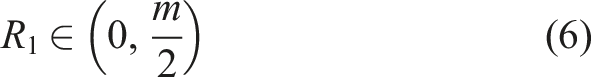
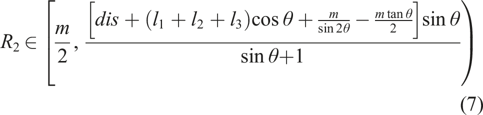
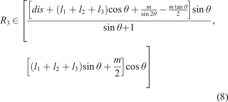
For a small-size cylinder, the palm and the finger stay at their initial postures, and we move the gripper right above the object with a distance between the palm base and the table as Grasping strategy for cylindrical objects.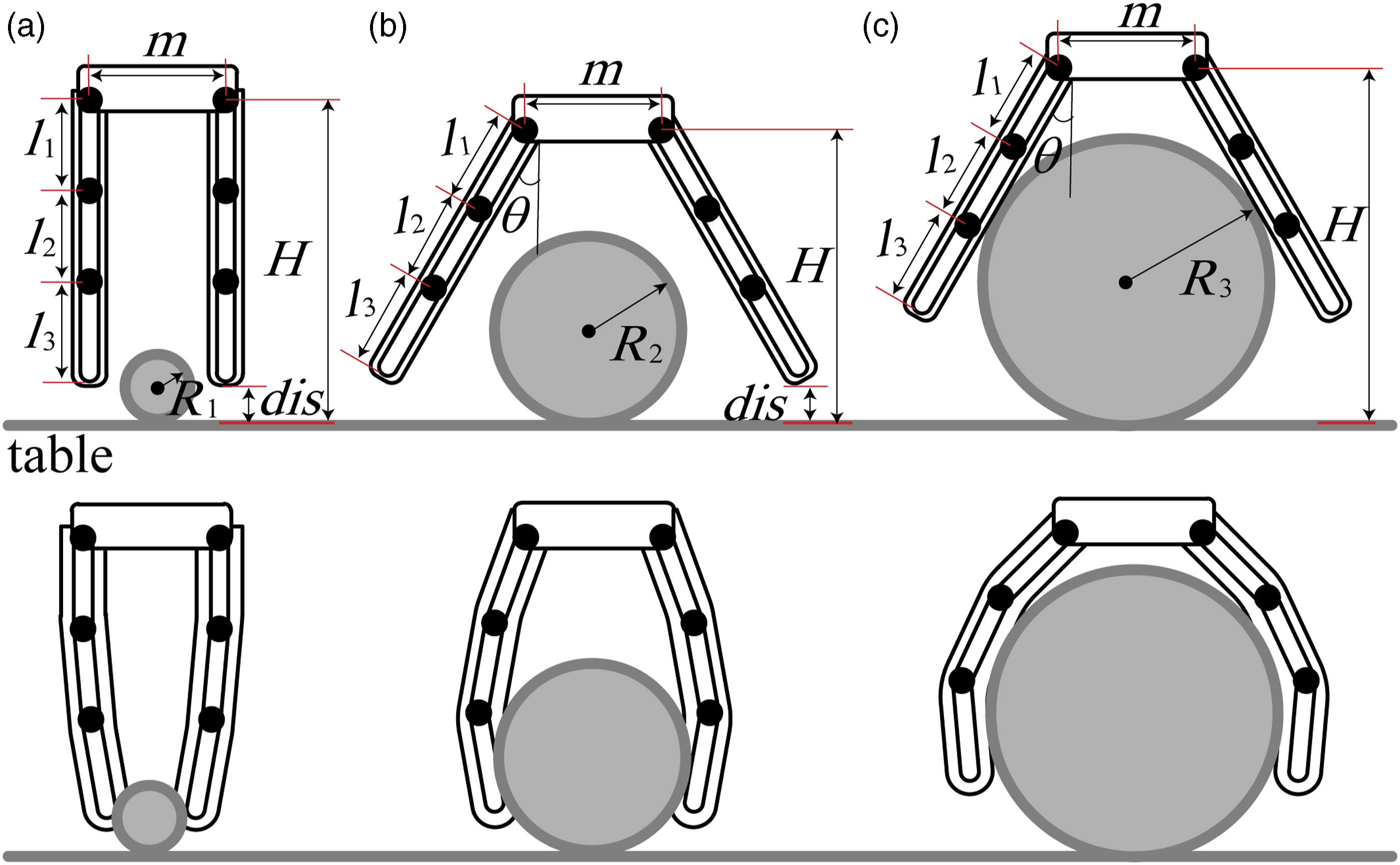
For the other two sizes cylinder, we have the following steps: first, open the palm to its maximum angle θ, then move the gripper’s palm on top of the object at a distance H from the table, then close the angle of the palm, and finally, inflate the soft skin to grasp the object. After inflating the fingers, lock the endoskeleton’s joints to enhance the stiffness and grasping force. If the gripper grasps a medium-sized object, the calculation of H is determined by dis (Figure 13(b)), we have
In the grasping for cylindrical objects, the functionality of the endoskeleton is mainly for enhancing the grasping stiffness, both vertically and laterally, as can be seen from Figure 10(c). It is worth noting that the adaptive capability of the finger when all joints are free can effectively generate a conformal grasping. Therefore, we simply set the pressure for grasping small, medium, and large cylinders as 30, 40, and 50 kPa, respectively.
6.1.2. Prismatic objects
For prismatic objects, there are three key dimensional parameters that will affect our grasping strategy: the width l, the height h, and the angle facing the gripper α (assume the object is symmetrical, see Figure 14). Figure 15 shows the flowchart of grasping prismatic objects: (i) If (ii) If (iii) If (iv) If (v) If Grasping postures for prismatic objects with different dimensions. (a) Grasping posture for Case 1. (b) Grasping posture for Case 2. (c) Grasping posture for Case 3. (d) Grasping posture for Case 4. (e) Grasping posture for Case 5. Flowchart for grasping prismatic objects.
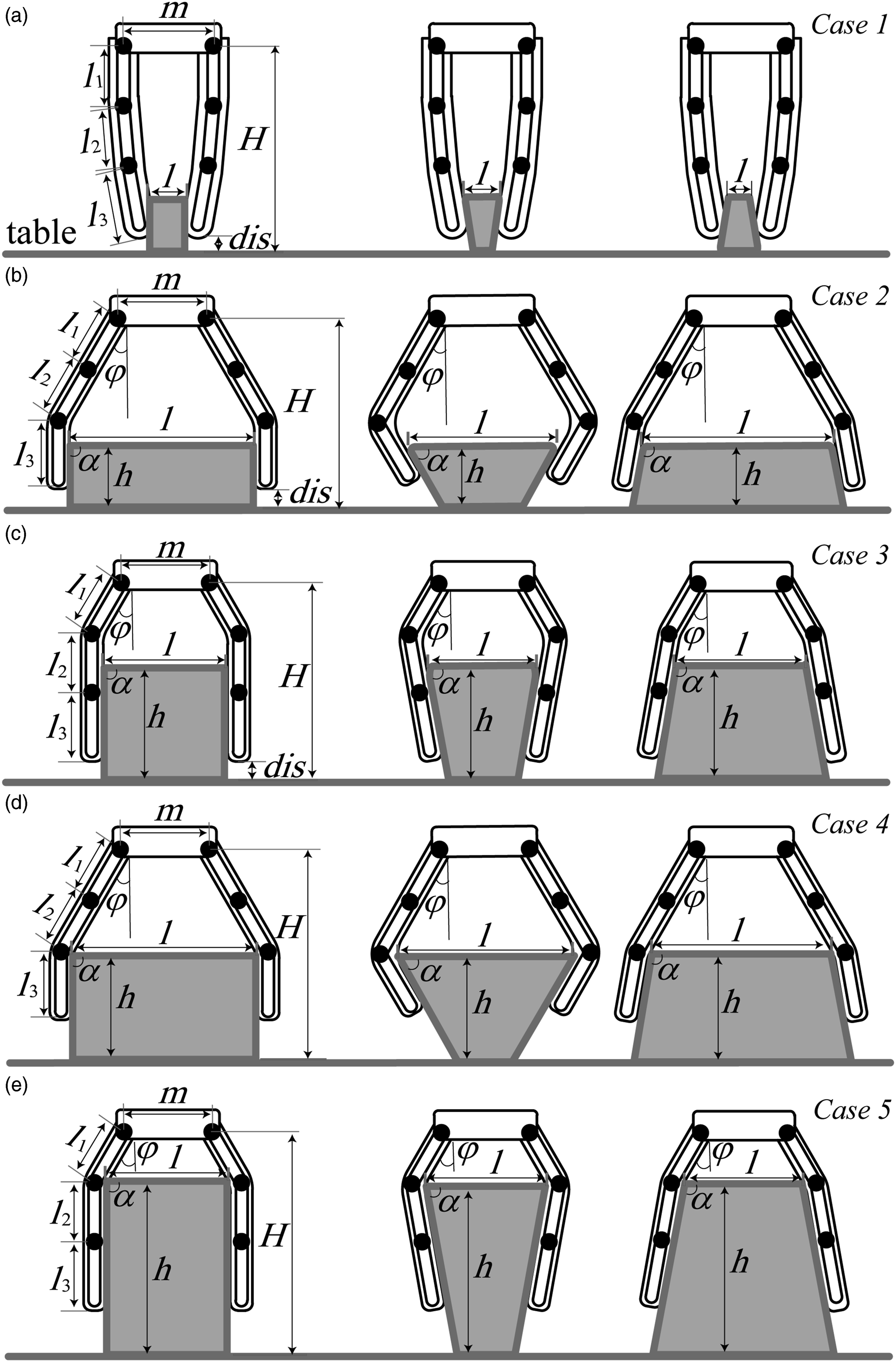
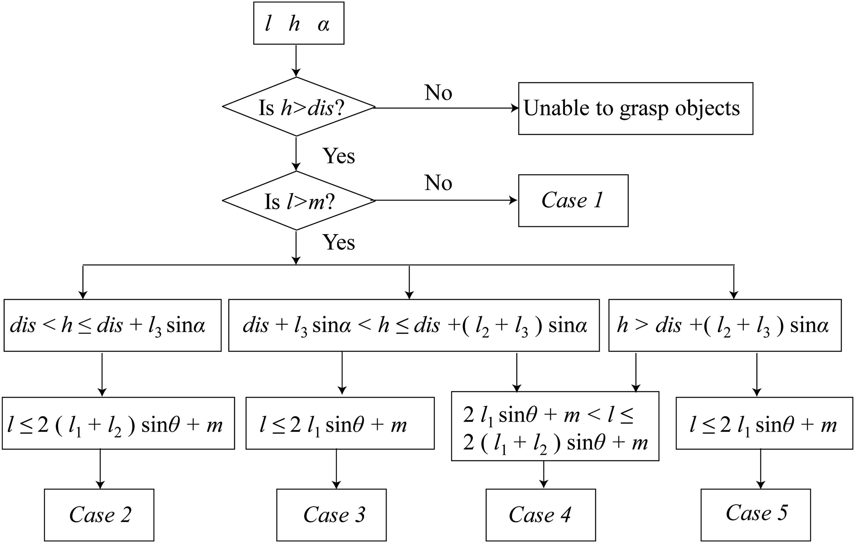
The grasping strategy for each case is as follows:
Set
open the palm to the maximum angle θ and move down the gripper until the distance between the gripper base and the desktop is
open the palm to the maximum angle θ and move down the gripper until the distance between the gripper base and the desktop is
open the palm to the maximum angle θ and move down the gripper until the distance between the gripper base and the desktop is
open the palm to the maximum angle θ and move down the gripper until the distance between the gripper base and the desktop is With the above strategy, any prismatic object with the dimension range We used the above strategies to grasp cylindrical and prismatic objects experimentally. We installed a monocular camera right in front of the object (see Figure 16(a)) and developed an algorithm to recognize the edge profile of the object’s cross section. The process of recognizing the shape of an object and obtaining its size is as follows. Place the object in a fixed position in advance, manually measure the distance between the object and the camera, and input the distance to the upper computer. The camera took photos of the object and transmits it to the upper computer. The upper computer used the proposed algorithm to recognize the shape of the object and calculate its size. The algorithm decided the shape of the object’s cross section (circle, rectangular, or trapezoidal) and then returns the key parameters of dimensions. Then this information was fed to the controller of the gripper to implement the designed grasping strategy. The gripper was fixed on a robotic arm (UR3). The high-pressure air source was from a pump. Each of the soft skin actuators and the palm actuators was controlled with a proportional valve to regulate the internal pressure. Each of the actuators within the endoskeleton was controlled with a two-position three-way solenoid valve. A PC with PyCharm was used to implement the strategy and control the valves through an analog I/O Module. For cross sections as circle, square, inverted trapezoid, and trapezoid with three sizes (5 cm, 10 cm, and 15 cm), the gripper adopted different grasping strategies and successfully picked up all the objects as shown in Figure 16(b) and Supporting Video S3. The gripper fit well on the surface of objects of different sizes, which demonstrated the effectiveness of our proposed grasping strategy. To verify the robustness of our recognition algorithm and the grasping strategy, we tested its grasping performance with a cuboid box and a water bottle from different orientations (Figure 17). For a cylindrical water bottle, the gripper adopted different strategies based on the recognized shape as circular or rectangular. Similarly, the gripper adopted different strategies with different cases based on the width, and height of the cuboid box (Supporting Video S4). These results preliminarily demonstrated both the algorithm and the strategy function effectively to utilize the versatile postures of the gripper.
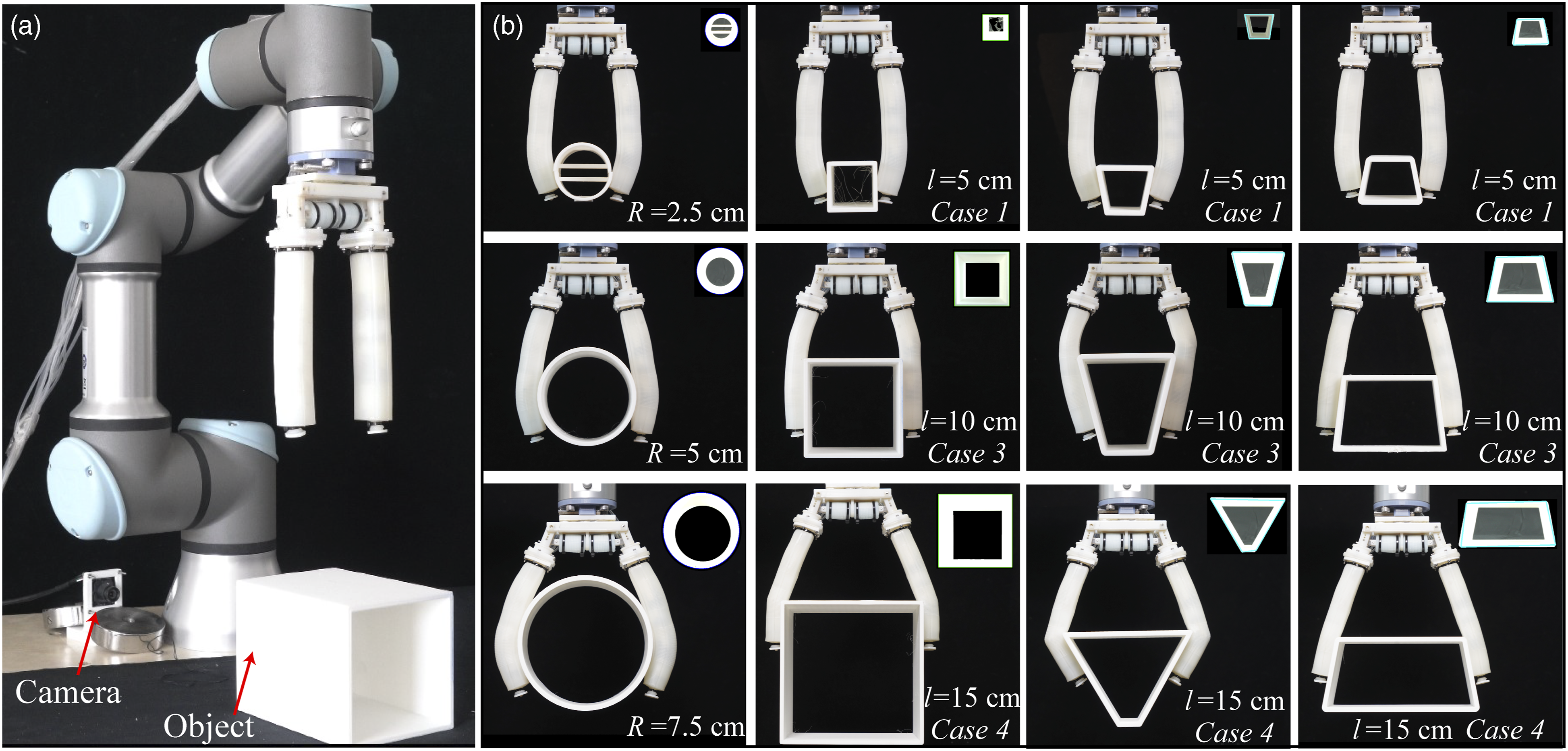
Grasping objects with different shapes and sizes using different strategies.
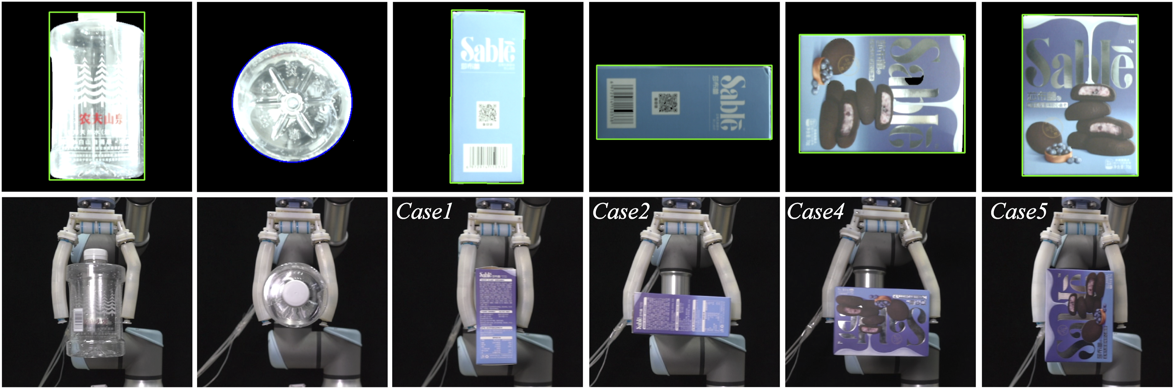
Grasping of a water bottle and a cuboid box from different orientation.
6.2. Grasping experiments with the gripper
In order to verify the overall grasping ability of the gripper, a series of grasping experiments were carried out. The process of the grasping experiment was: grasp the object, hang the object vertically for 3 seconds, and re-orient the objects horizontally for 3 seconds, and then move the object a certain distance (about 20 cm) to another position and put it down (Figures 18 and 19). If the object does not fall during this whole process, it is regarded as a successful grasping. The process of grasping a football. (a) Initial state. (b) Open palm. (c) Inflate the skin, lock the endoskeleton, close the palm, and grasp the football. (d) Hang the object vertically for 3 seconds. (e) Re-orient the object horizontally for 3 seconds. (f) Return to vertical state. (g) Move the object to another position. (h) Put down the object. The process of grasping a pair of scissors. (a) Initial state. (b) Open the angle between the fingers. (c) Inflate the fingers and lock the endoskeleton. (d) Deflate the fingers. (e) Move the gripper down close to the scissors. (f) Close the palm and grasp the scissors. (g) Hang the object vertically for 3 seconds. (h) Hang the object horizontally for 3 seconds. (i) Return to vertical state. (j) Move the object to another position. (k)-(l) Put down the object.

In the process of grasping objects, two grasping methods were often used. One was to inflate the fingers, lock the endoskeleton, and grasp the object, such as grasping various balls (Figure 18). The other was to bend the revolute joints of the endoskeleton to a certain angle in advance, and then deflate the fingers to grasp objects such as tools: scissors, wrenches, screwdrivers, claw hammers, etc. (Figure 19). The latter method is suitable for grasping objects with relatively high density.
We grasped tool items and shape items in Yale–Carnegie Mellon University (CMU)–Berkeley (YCB) object set with this gripper (Calli et al., 2015). The items used in our test were not exactly the same as in the YCB object sets due to unavailability of purchase, but we have prepared items as close as to the set in terms of size, shape, and weight. For objects with small height (e.g., washers, card, nuts, clamp, pen, nails, racquetball, golf ball, marbles, scissors, screwdrivers and wrenches), we either put them on a holder to lift up, or oriented them vertically. With such adjustment, the grasping success rate was 100% (Figure 20 and Supporting Video S5). Figure 20 shows the state of the gripper grasping the object vertically and horizontally. The rigid piece (Figure 1(b)) at the tip of each finger played an important role in grasping heavy or small objects, especially pens, locks, glass balls, and some other objects. Grasping experiments of objects in the YCB object set in both the vertical and horizontal directions.
For more practical applications, it is more reasonable to pick up objects directly from a flat table. Therefore, in Supporting Video S6, we implemented a direct picking from the table for objects that need to be manually oriented in Supporting Video S5. Here, we used the specially designed “fingernail” as in Figure 12(a) and a pinch strategy for grasping. With the assistance of the “fingernails,” the gripper successfully picked up, rotated, and placed small, thin, and light objects such as washers, cards, nuts, clamp, pen, nails, racquetball, golf ball, and marbles. The thinnest object that the gripper could grasp was a student card with a thickness of 0.8 mm.
However, for some thin but heavy objects such as screwdrivers and wrenches, even though the gripper successfully achieved the picking and placing from the vertical direction, it failed in rotating them laterally. These failures were mainly due to the small pinch force of our gripper as shown in Figure 12(c).
For some objects that were difficult to grasp vertically, especially those that need envelope grasping, we grasped them laterally. This is because the gripper incorporated endoskeletons, which enhances its lateral stiffness. In Supporting Video S7, we show several typical cases of lateral grasping. There was a square box that failed to be grasped in our past work (Cui et al., 2021), yet in this work, it was successfully grasped by lateral grasping. In the process of grasping these objects, we shook the gripper, and the objects did not fall, which demonstrated that our gripper had sufficient stiffness and grasping stability. By grasping the objects in different directions, the functionality of the gripper was further expanded to, such as, grasping the objects into a narrow space, placing the object in a fixed direction, etc. (Wei et al., 2022). It is worth noting that the gripper could grasp a drill but could hardly rotate the drill. This was mainly due to our gripper had only two fingers, and when grasping the handle and rotating, the heavy weight on the head side would cause a rotation of the drill itself, thus causing slippery from the gripper.
6.3. Manipulation demonstration with the gripper
Due to the multiple and independently-controllable actuators of our gripper, besides grasping, we believe our gripper possesses the capability of manipulating objects. To demonstrate such potential capability, we supplemented a video (Supporting Video S8) showing the in-hand rotating of a plastic bottle placed on a table by inflating one palm actuator and one finger actuator alternatively, while the other finger and palm actuator serving as a boundary wall (the processes from a top-down view are shown in Figure 21). During the rotating process, all four joints of the non-actuating finger were locked, and the PIP joint on the actuating finger was locked (the other three joints are free). This manipulation utilized the finger skin’s slight elongation and shrinkage during the inflating and deflating process. It took the gripper 2.5 min to rotate the bottle a full cycle. More sophisticated strategies to manipulate objects can be designed to further utilize the gripper’s palm actuators, finger actuators, and endoskeleton joints. Demonstration showing the gripper’s capability of manipulating objects. Step 1—the palm actuator is inflated and the finger actuator is deflated, step 2—the finger actuator is inflated, step 3—the palm actuator is deflated so that the finger gets in touch with the bottle, step 4—the finger actuator is deflated and friction between the finger and the bottle causes the bottle to rotate a small angle counterclockwise. Repeating the above cycle and the bottle being continuously rotated.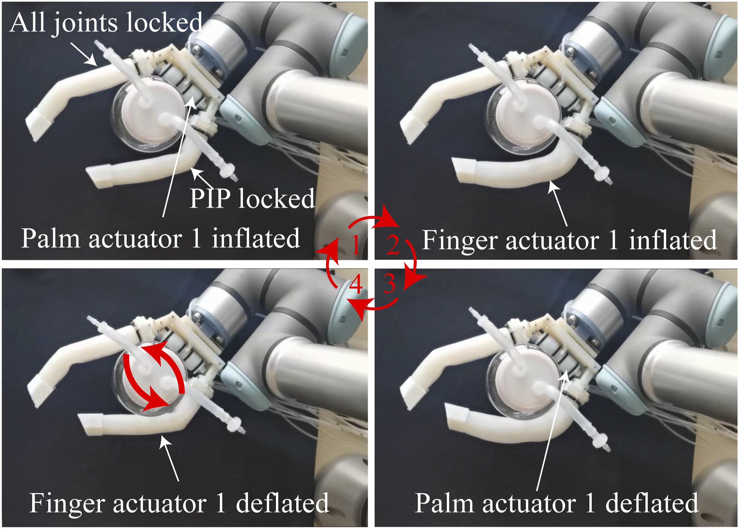
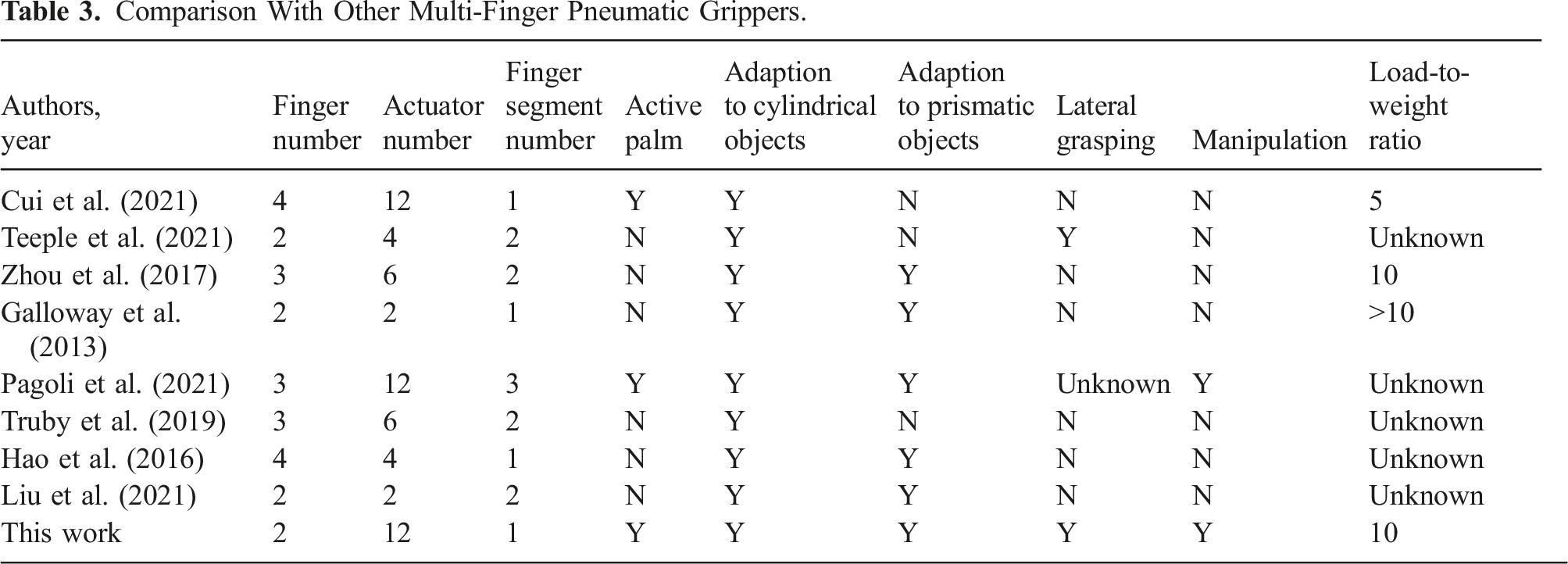
Comparison With Other Multi-Finger Pneumatic Grippers.
7. Conclusion and future work
In this paper, we proposed a soft-rigid hybrid pneumatic gripper with rigid endoskeletons, soft skins, and an active palm. Through the combination of rigid endoskeletons and soft skins, the gripper exhibited a compact structure, diverse grasping postures, good adaptability, and enhanced stiffness. The adaptability of our gripper was achieved through simply controlling the sequential on/off states of the joints rather than their accurate positions. This semi-active method makes the grasping process robust and straightforward. We proposed a series of strategies for grasping objects of different sizes and shapes to utilize the versatility of the gripper. Experiments demonstrated that the gripper fit well on the surface of cylindrical and prismatic objects. Grasping experiments on Yale–Carnegie Mellon University–Berkeley (YCB) object set further show its capability and robustness in grasping various objects. We believe the versatility and easy controlling method of our gripper can facilitate more interesting grasping strategies for irregular objects.
However, some questions are remaining for further improvement. Our design for the revolute joint locking is a gear-like structure with a tooth and multiple grooves. This locking mechanism can only lock at some discrete angles, which may reduce the controllability of the finger to the accurate desired posture, thus affecting the grasping precision. In the future, a more continuous locking mechanism for the revolute joints is expected. Next, the pinch force of the gripper is relatively small, which causes grasping failures for thin and heavy objects directly from the table (Supporting Video S6). This relatively small pinch force is mainly due to the compliance of the palm and thus could be enhanced by adding the locking endoskeleton into the palm actuators. Also, vacuum has been widely used to tune and enhance stiffness by enveloping rigid pieces with a sealed skin (Wang et al., 2021; Gao et al., 2022). Simply introducing a vacuum besides the positive pressure to our gripper’s soft skin actuator and palm actuator may further increase its grasping stability and stiffness. Finally, in this work, we have preliminarily demonstrated our gripper’s manipulation capability. Due to the diverse postures that can be generated, we believe more sophisticated strategies would endow the gripper with more dexterous manipulation, which is equally important as the grasping adaptability for practical usages in the future.
Supplemental Material
Supplemental Material
Supplemental Material
Supplemental Material
Supplemental Material
Supplemental Material
Supplemental Material
Supplemental Material
Footnotes
Acknowledgements
The authors would like to thank Prof. Fugui Xie, Porf. Zhengguo Nie, Qi Shao, Boyuan Du, and Yifei Li for assistance in designing the gripper and performing experiments.
Declaration of conflicting interests
The author(s) declared no potential conflicts of interest with respect to the research, authorship, and/or publication of this article.
Funding
The author(s) disclosed receipt of the following financial support for the research, authorship, and/or publication of this article: This work was funded by the National Natural Science Foundation of China (grant number. 52222502, 51975306, and 92048302).
Supplemental Material
Supplemental material for this article is available online.
References
Supplementary Material
Please find the following supplemental material available below.
For Open Access articles published under a Creative Commons License, all supplemental material carries the same license as the article it is associated with.
For non-Open Access articles published, all supplemental material carries a non-exclusive license, and permission requests for re-use of supplemental material or any part of supplemental material shall be sent directly to the copyright owner as specified in the copyright notice associated with the article.