
Abstract
Deployment of legged robots for navigating challenging terrains (e.g., stairs, slopes, and unstructured environments) has gained increasing preference over wheel-based platforms. In such scenarios, accurate odometry estimation is a preliminary requirement for stable locomotion, localization, and mapping. Traditional proprioceptive approaches, which rely on leg kinematics sensor modalities and inertial sensing, suffer from irrepressible vertical drift caused by frequent contact impacts, foot slippage, and vibrations, particularly affected by inaccurate roll and pitch estimation. Existing methods incorporate exteroceptive sensors such as light detection and ranging (LiDAR) or cameras. Further enhancement has been introduced by leveraging gravity vector estimation to add additional observations on roll and pitch, thereby increasing the accuracy of vertical pose estimation. However, these approaches tend to degrade in feature-sparse or repetitive scenes and are prone to errors from double-integrated IMU acceleration. To address these challenges, we propose
1. Introduction
Legged robots have increasingly attracted attention for their robust mobility and adaptability in harsh environments, where traditional wheeled unmanned grounded vehicle (UGV) systems often struggle. Their ability to traverse stairs, steep slopes, uneven surfaces, and unstructured terrain makes them well suited for real-world deployment in search-and-rescue, inspection, and exploration tasks (Tranzatto et al., 2022a). To fully leverage these capabilities in practice, it is essential to ensure accurate odometry estimation, which underpins stable locomotion, localization, and mapping in such challenging scenarios (Figure 1). Overall preview of GaRLILEO. The four subfigures in the upper row present the problematic situations that quadrupedal robots may encounter while performing real-world tasks, while the yellow letters specify the situations and the red words explain the substantial issues generated from them. Two boxes in the left part of the lower row summarize the major contribution and method of the GaRLILEO, which significantly reduces odometry error, especially in the vertical direction. Two graphs in the right part of the lower row present the short experimental results, showing the accuracy of GaRLILEO in multiple sequences that include loops, sharp turns, and staircases, where most baselines fail to maintain accuracy in odometry estimation.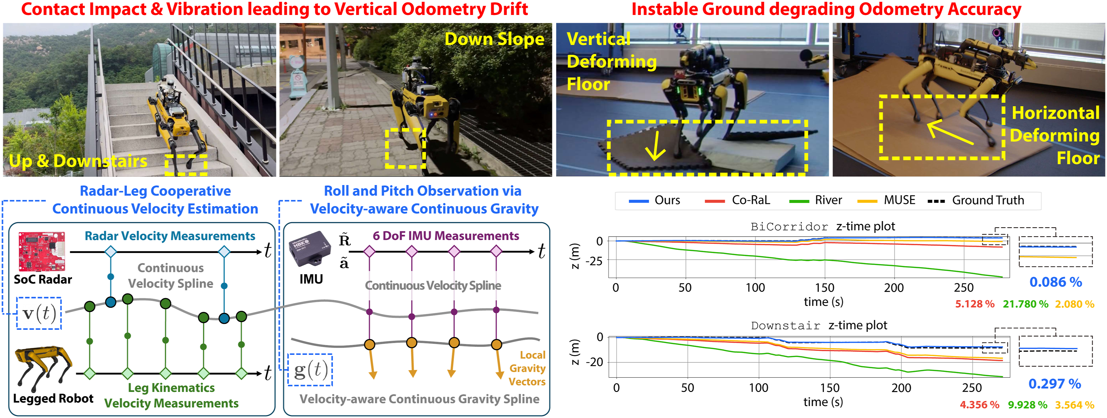
A common practice for robust state estimation in legged robots is leveraging proprioceptive sensing, which directly captures internal kinematics of the robot through contact measurements, joint encoders, and inertial sensing (Hartley et al., 2018b, 2020; Kim et al., 2021; Lin et al., 2023; Yang et al., 2023a). These proprioceptive approaches capitalize on the direct sensing of robot dynamics as they do not depend on external observations, making them inherently robust to visual or geometrical degradation. Nonetheless, frequent contact impacts, foot slippage, and intense vibrations significantly impair the accuracy of proprioceptive odometry, particularly in the vertical direction.
A natural progression to address this vertical drift is to leverage exteroceptive sensors, such as cameras and LiDARs. Most LiDAR-based methods apply ground segmentation and ground constraints to suppress vertical errors (Seo et al., 2022; Shan and Englot, 2018; Wang et al., 2024; Wei et al., 2021). However, these strategies are mainly effective in wide, flat, and structured environments, which differ significantly from the cluttered and irregular terrains targeted by legged robots. Camera-based approaches also frequently rely on planar segmentation and Manhattan world assumptions to constrain vertical error (Li et al., 2020; Shu et al., 2021), yet these assumptions break down in complex natural environments. Moreover, recent studies further indicate that simply introducing planar landmarks may not guarantee direct improvement in managing odometry drift (Arndt et al., 2023), underscoring the limitations of exteroceptive registration in realistic legged robot scenarios.
Using an inertial measurement unit (IMU) with cameras and LiDARs can significantly enhance the state estimation. Among its many advantages, gravity estimation provides additional constraint for roll and pitch, enhancing state estimation, a concept that was first introduced in VINS-Mono (Qin et al., 2018). While some studies (Agha et al., 2021; Kubelka et al., 2022; Nemiroff et al., 2023; Ramezani et al., 2022; Wang et al., 2023) report notable improvements, others indicate only marginal performance gains (Burnett et al., 2025). This may be because most existing methods rely on fusing IMU acceleration with pose estimates. Such fusion requires double integration, and the gravity estimate inherently depends on the quality of the pose estimation. Consequently, feeding this pose-dependent gravity estimate back into the state may provide only limited improvement.
A promising alternative for overcoming these limitations is the use of radar. By providing direct velocity measurements, radar can fuse its ego-velocity with IMU acceleration via single integration for local gravity estimation (Noh et al., 2025). While effective, this integration can be limited in legged robot operations, where velocity changes sporadically due to frequent contacts and impacts. Another more intuitive way to integrate radar into the legged robot system is by utilizing the instantaneous ego-velocity derived from the leg kinematics as in Co-RaL (Jung et al., 2024). This approach takes advantage of radar’s ability to operate reliably under environmental degradation while also utilizing the high-frequency, proprioceptive information provided by leg kinematics sensors. However, despite these improvements, residual vertical drift persists due to inaccurate roll and pitch estimation. This limitation primarily stems from the exclusive reliance on IMU gyroscopes for orientation.
To bridge the critical gap between proprioceptive odometry and robust gravity estimation, we extend our previous works GaRLIO (Noh et al., 2025) and Co-RaL (Jung et al., 2024) to complete
Beyond seamless fusion between radar and leg kinematics, the fundamental challenge of pose estimation of legged robots lies in the contact impacts and vibrations that persistently corrupt gravity estimation. To suppress these sudden, undesired acceleration measurements from the IMU, we employ splines as an inherent filter, bounding the gravity vector within a smoothed, continuous vector space. Furthermore, to naturally constrain the magnitude of the gravity vector during optimization, we introduce • The proposed continuous-time proprioceptive state estimation framework effectively overcomes the asynchronous, high-impact nature of radar-Leg-IMU systems. By formulating ego-centric velocity through splines and decoupling it from noisy IMU accelerations, abrupt motion prevalent in legged locomotions is better handled. This continuous formulation inherently filters out instantaneous leg slips and radar noise, providing a stable, distortion-free foundation for downstream gravity and pose estimation without relying on visual or LiDAR features. • Our velocity-aware gravity estimation directly attacks the pervasive issue of vertical drift in legged odometry. By integrating a soft • We present a comprehensive, real-world radar-Leg-Inertial dataset which features aggressive elevation changes across stairs, slopes, and slippery indoor/outdoor terrain. Validated against high-fidelity terrestrial laser scanning (TLS) and motion capture ground truth trajectories, GaRLILEO demonstrates state-of-the-art (SOTA) performance, proving exceptionally resilient to z-axis variations where traditional methods fail. To foster further research, both the dataset and framework source code are released to the community.
2. Related works
In this section, we review prior work most relevant to our approach. We begin with system on chip (SoC) radar odometry methods that leverage ego-velocity estimation. We then turn to recent developments in odometry for legged robots, covering both exteroceptive and proprioceptive paradigms. Building on this, we highlight advances in gravity estimation within state estimation frameworks. Lastly, we review continuous-time odometry methods that are particularly relevant to our work.
2.1. SoC radar odometry
Radars have emerged as a critical sensing modality in robotics, offering robust perception in adverse environments (Harlow et al., 2024). Robotics applications commonly utilize two types of radars: spinning radars and phased-array SoC radars (Kim et al., 2025b). This paper mainly focuses on SoC radars, which employ Frequency modulated continuous wave (FMCW) technology to generate 4D point clouds capturing range, azimuth, elevation, and Doppler radial velocity. While structurally similar to LiDAR data, SoC radar measurements are typically sparser and exhibit lower point precision, posing unique challenges for odometry estimation.
A primary approach to leveraging SoC radar for odometry involves directly estimating ego-velocity using point-wise radial velocity measurements. Early work by Kellner et al. (2013) introduced instantaneous ego-motion estimation using random sample consensus (RANSAC) for outlier rejection and least-squares optimization for a single SoC radar. Building on this foundation, subsequent studies can be categorized into two main directions: those integrating spatial information into ego-velocity estimation and those fusing it with inertial measurements from IMUs.
Several approaches have explored the integration of spatial information from SoC radar point clouds. For example, Michalczyk et al. (2022) utilized stochastic cloning to associate 3D points between consecutive point clouds, thereby enhancing odometry accuracy. Similarly, 4D-iRIOM (Zhuang et al., 2023) combined SoC radar velocity with scan-matching techniques, improving robustness by aligning scan-to-submap registration with Doppler-driven ego-velocity estimates. Recently, Huang et al. (2024) introduced radar cross section (RCS)-based filtering to refine point correspondences. Despite these advancements, the low precision and sparsity of SoC radar point clouds often make registration vulnerable, leading to unbounded drift or failure in odometry estimation under challenging conditions.
In contrast to registration-based methods, other studies have integrated ego-velocity estimation with inertial measurements from IMUs. For instance, Doer and Trommer (2020) employed an extended Kalman filter (EKF), while Park et al. (2021) utilized factor graph optimization to achieve 6-degree of freedom (DoF) odometry in visually degraded environments. Specifically, Park et al. (2021) leveraged two perpendicular SoC radars for 3D ego-velocity estimation and introduced a radar velocity factor for pose-graph simultaneous localization and mapping (SLAM) that incorporates IMU rotation data. More recently, DRIO (Chen et al., 2023) estimated ego-velocity and ground points, achieving robust 2D odometry. Also, Co-RaL (Jung et al., 2024) proposed a 4-DoF optimization strategy to mitigate vertical drift caused by the limited elevation resolution of SoC radars. Similarly, DeRO (Do et al., 2024) employed dead reckoning with SoC radar ego-velocity and gyroscope data, further refined through an iterative extended Kalman filter (IEKF) with tilt angle estimation based on accelerometers. Recently, River (Chen et al., 2024) tightly fused SoC radar ego-velocity and IMU measurements using a B-spline-based framework, presenting precise velocity estimation.
While prior works have significantly advanced SoC radar odometry by leveraging ego-velocity and spatial information, they face persistent challenges in mitigating vertical drift and ensuring robust performance under the dynamic conditions of legged robot systems. In such scenarios, low-precision vertical velocity measurements from SoC radars and contact-induced noise in IMU acceleration data often contribute to significant vertical drift in odometry estimation. Most existing methods either suffer from unbounded drift due to insufficient vertical constraints or rely on point cloud registration schemes that are highly sensitive to radar noise and sparsity. To overcome these limitations, our proposed method, GaRLILEO, seamlessly integrates radar-derived ego-velocity with high-rate proprioceptive measurements within a continuous-time framework, significantly reducing odometry distortion. Furthermore, our robust proprioceptive-based local gravity estimation scheme effectively mitigates vertical drift, enabling stable and accurate odometry even in dynamic and complex environments.
2.2. Leg kinematics odometry
Compared with traditional wheeled UGV, a legged robot provides two unique sensor modalities: (1) contact sensors, which indicate the contact state of each foot, and (2) joint encoders, which measure the orientation of each joint. Using forward kinematics, the relative position of each foot with respect to the robot base can be computed (Roston and Krotkov, 1992), completing leg-based odometry. The leg odometry can be divided into two categories: methods that leverage exteroceptive sensors such as LiDAR or cameras, and those that focus primarily on fusing proprioceptive sensors alone.
2.2.1. Exteroceptive approach
A wide range of odometry frameworks for legged robots have harnessed exteroceptive sensors—such as cameras and LiDAR—in combination with leg kinematics, to capitalize on feature-rich geometric information. Fallon et al. (2014) introduced a pose estimator that fuses inertial and leg kinematics measurements with localization derived from LiDAR and pre-built maps. Similarly, Nobili et al. (2017) fused inertial, leg kinematics, camera, and LiDAR measurements based on the EKF, demonstrating robust state estimation across multiple walking gaits. This line of work was further extended by Pronto (Camurri et al., 2020), which focused on managing time-delayed signals from the vision sensors and fusing leg kinematics velocity from each leg by using a weighted average. VILENS (Wisth et al., 2022) proposed a tightly-coupled, graph-optimization-based approach by fusing camera, LiDAR, leg kinematics sensors, and IMU. This work enabled temporal proprioceptive odometry based on the preintegration factor when exteroceptive sensors failed under extreme conditions. STEP (Kim et al., 2022) improved the stability of stereo camera-based odometry by incorporating leg kinematics, achieving robust performance in dynamic scenes. Similarly, Leg-KILO (Ou et al., 2024) demonstrated stable LiDAR-based odometry by leveraging leg kinematics during dynamic movements of legged robots. Cerberus (Yang et al., 2023b) introduced online calibration of kinematics parameters and contact outlier rejection to reduce drift in camera-IMU-leg kinematics odometry. To address dynamic locomotion behaviors such as jumping and trotting at varying speeds, Dhédin et al. (2023) fused leg odometry from Pronto (Camurri et al., 2020) with IMU frequency speed camera-IMU odometry. Recently, MUSE (Nisticò et al., 2025) integrated foot-slip detection with camera-LiDAR odometry to further enhance robustness. Holistic Fusion (Nubert et al., 2025) provided a unified framework in which leg odometry, especially using the contact frame as a landmark feature, could be seamlessly fused with exteroceptive sensors.
While these exteroceptive sensor-based approaches have shown strong odometry performance—especially when combined with leg kinematics information—they still encounter challenges in environments where perceptual features are sparse, ambiguous, or repetitive. In particular, visual and LiDAR odometry can degrade rapidly in poorly illuminated areas, featureless corridors, reflective surfaces, or in the presence of dense smoke and dust, limiting their reliability in many real-world legged robot applications.
2.2.2. Proprioceptive approach
In contrast to exteroceptive approaches, proprioceptive-based odometry estimates the robot pose without dependence on external features. Bloesch et al. (2012) introduced an EKF-based framework that fused leg kinematics measurements and IMU data for state estimation, which was later extended to a unscented Kalman filter (UKF) backbone (Bloesch et al., 2013).
Based on the contact theorem that a contact frame is fixed while a contact sensor is on, Hartley et al. (2018b) proposed a forward kinematics factor and a preintegrated contact factor. This was later generalized to a hybrid contact factor that dynamically switches the contact frame based on the assumption that at least one foot is in contact with the ground (Hartley et al., 2018a). The contact kinematics theory was incorporated into an invariant EKF framework, yielding a Lie group-based estimator that achieved globally consistent state estimation using IMU, kinematics, and contact measurements (Hartley et al., 2020). Fink and Semini (2020) additionally fused force and torque sensor data to develop a low-level state estimator, calculating both kinematics and dynamics of the robot. Still, the possible foot slip, even with the contact sensor in place, remains a challenge.
To address foot slip on the contact frame, approaches from various directions have been introduced recently. TSIF (Bloesch et al., 2017) presented a recursive estimation framework minimizing the residual between two consecutive states and demonstrated improved resilience to measurement outliers. Kim et al. (2021) adopted a fixed-lag smoother state estimation on the SO(3) manifold, paired with slip rejection strategies to mitigate kinematics model failures. DRIFT (Lin et al., 2023) combined contact estimation and gyro filtering within an invariant EKF, enabling robust odometry on low-cost legged robots. Yang et al. (2023a) utilized multiple IMUs on each foot to explicitly detect contact and foot slip, overcoming the zero-velocity contact frame assumption prevalent in contact sensor-based proprioceptive odometry studies.
Although proprioceptive odometry is robust to environmental conditions and feature degradation, it suffers from drift over time, particularly in the vertical direction, due to the drastic vibration from contact impact and the lack of an absolute orientation reference. To address this, Co-RaL (Jung et al., 2024) introduced an integration of SoC radar-derived ego-velocity with leg kinematics velocity incorporating rolling contact awareness. However, despite these integrated measurements, vertical drift remains due to inaccurate roll and pitch estimation. This stems from not accounting for IMU acceleration, which contains critical information, such as the gravity vector, essential for accurate odometry.
GaRLILEO improves upon Co-RaL by integrating SoC radar, leg kinematics, and IMU data using a continuous-time B-spline approach and introducing robust continuous velocity-aware gravity estimation. This enables substantially improved robustness of odometry, especially in the vertical direction, compared to Co-RaL and other purely proprioceptive methods.
2.3. Local gravity estimation
Gravity, with its constant magnitude and direction, provides a physically grounded reference for reliable roll and pitch estimation in odometry and SLAM. Accurate roll and pitch estimation is crucial for mitigating vertical drift, which is stimulated by erroneous leakage of horizontal movement onto the vertical axis. Accordingly, accurate local gravity estimation has emerged as a critical constraint for suppressing accumulated vertical drift errors in state estimation frameworks.
Early gravity estimation in LiDAR odometry typically inferred the local gravity vector from IMU acceleration or employed probabilistic filtering over time. Nebula (Agha et al., 2021) introduced a gravity factor based on IMU acceleration during stationary intervals, constraining roll and pitch in the state estimation. D-LIOM (Wang et al., 2023) and Wildcat (Ramezani et al., 2022) formulated gravity alignment as an optimization constraint using IMU data and exteroceptive-based odometry. Nemiroff et al. (2023) further extended this by jointly optimizing accelerometer intrinsics and the gravity vector. While these velocity-ignorant models presented the potential for local gravity estimation to mitigate odometry vertical drift, they fundamentally relied on correlating pose changes from exteroceptive odometry with IMU acceleration, which amplified errors due to IMU bias and noise through the process of double integration. This limitation hinders robustness in dynamic environments or those prone to slippage. Furthermore, Burnett et al. (2025) report that these methods offer only marginal performance gains; this is likely due to the inherently pose-dependent nature of velocity-ignorant gravity estimation, which limits the benefit of feeding estimation back into the state.
To overcome these issues, GaRLIO (Noh et al., 2025) explicitly incorporated direct velocity measurements from radar Doppler data for local gravity estimation. By fusing radar-derived ego-velocity with LiDAR odometry, GaRLIO constructed a velocity-aware gravity constraint that significantly enhanced the accuracy of gravity estimation. However, GaRLIO still depended on an initial gravity guess from LiDAR scan registration, making it susceptible in feature-degraded environments or unadaptable to a system without LiDAR. Additionally, mismatches in time intervals between the IMU preintegration and radar ego-velocity updates may introduce estimation inconsistencies due to the lack of continuity in the discrete-time sensor-fusion approach.
In contrast, our GaRLILEO framework integrates a continuous velocity-aware local gravity estimation approach, enabling precise and robust estimation of the gravity vector even in visually degraded or featureless environments. Furthermore, by continuously fusing SoC radar velocity and leg kinematics measurements via a time-continuous B-spline optimization framework, GaRLILEO prevents the inconsistency that may arise from discrete sensor fusion across modalities with differing frame rates.
2.4. Continuous-time state estimation
Sensor fusion is essential in robotics to leverage the complementary strengths of heterogeneous sensors. Traditional discrete-time frameworks synchronize each sensor by associating with the nearest available timestamp; however, this introduces motion distortion and overlooks latent state information between sampled states (Talbot et al., 2024).
To address this limitation, recent works have adopted B-spline-based continuous-time trajectory representations, enabling smooth and differentiable state estimation that supports querying poses, velocities, and accelerations at arbitrary time instances. Furgale et al. (2012, 2015) formulated batch estimation of robot trajectories in SE(3) using temporal B-splines, establishing the groundwork for continuous-time sensor fusion.
Ovrén and Forssén (2019), Hug and Chli (2020), Lang et al. (2022), and Hug et al. (2022) extended these ideas for vision-inertial fusion, achieving improved robustness to motion distortion and asynchronous measurements. Similarly, Droeschel and Behnke (2018) leveraged B-splines for continuous-time SLAM with LiDAR-inertial system. Later, recent works like Lang et al. (2023, 2024) and Lv et al. (2023) addressed multi-modal SLAM and odometry between LiDAR, camera, and IMU. Jung et al. (2023) further addressed asynchronous fusion for multi-LiDAR-IMU odometry using B-spline approach for continuous-time formulations. For SoC radar-IMU systems, River (Chen et al., 2024) introduced a B-spline-based radar-inertial velocity estimator that could operate robustly under perception-degraded conditions.
Inspired by these recent advances, GaRLILEO presents the first integration of leg kinematics with SoC radar and IMU in a continuous-time B-spline framework. By directly incorporating leg kinematics velocities and radar measurements at their respective timestamps without preintegration, GaRLILEO provides more accurate and robust state estimation. Additionally, this continuous-time framework even enhances the gravity estimation accuracy, reducing the vertical drift, especially in challenging legged robot scenarios where slip and dynamic contact events frequently occur.
3. Preliminary
In this section, we summarize the background for the following sections.
3.1. Radar radial velocity and ego velocity
Leveraging the FMCW technique, phased array radar can provide not only the 3D position of the points that they acquire, but also the radial velocity of the point in the sensor coordinate. If a single radar point is generated from a stationary object, the radial velocity of the point can be represented with the ego-centric velocity of the sensor. Let the ego-centric velocity of the sensor is
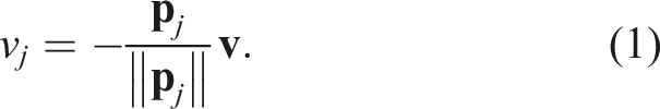
Using this radial velocity, we can calculate ego-velocity using RANSAC and least-square optimization processes (Kellner et al., 2013). For a simple illustration, let’s assume that the radar acquires only 2D data. Then, equation (1) can be expressed as follows:
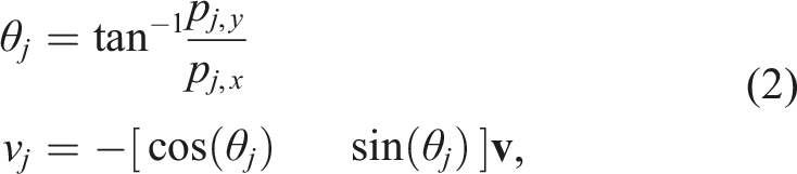
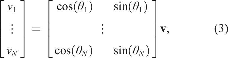
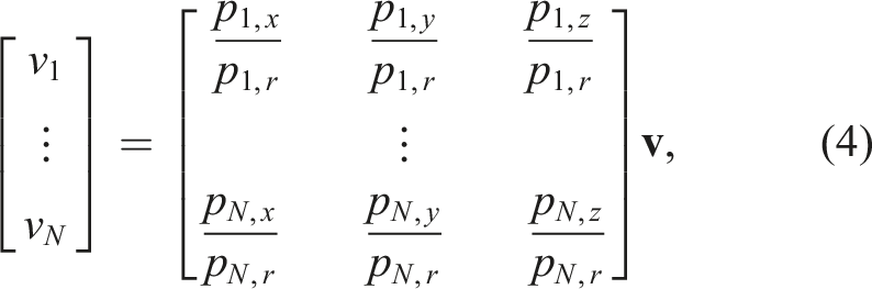
Based on equation (3) or equation (4), whether the data is 2D or 3D, if the matrix including the angular information of points is referred to as
3.2. Leg kinematics and ego velocity
Two key sensors for state estimation of the legged robot are the joint encoders and contact sensors. Joint encoders measure the absolute angle of each joint, being a key proprioceptive sensor for estimating the robot’s pose. Contact sensors are positioned at every foot, measuring whether the foot is currently in contact or not.
Using the joint encoder measurement and the physical modeling of each node, the relative coordinate transformation between frames
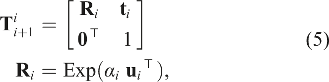

Under the no-slip assumption, when a single contact is made on any foot, the contacting frame of the foot should remain static until the contact state is resolved. Using this, during a foot is remaining contact state, the relative velocity of the base frame can be calculated by inverting the forward kinematics function to estimate the pose difference of the base frame during the contact state.
From this forward kinematics, we will derive the ego-centric velocity and use it for the velocity factor, which will be detailed in Section §4.3.
3.3. B-spline interpolation
A k-order B-spline consists of several polynomial segments of degree k − 1 with at most Ck−2 continuity (Patrikalakis and Maekawa, 2002). This continuous-time spline representation allows evaluating the state at arbitrary timestamps via smooth interpolation, which is particularly useful for fusing asynchronous sensors and reduces the need for explicit sensor-to-sensor time synchronization by enabling direct evaluation at each measurement time. Moreover, for legged robots where gait patterns introduce high-frequency noise, the smoothness of the spline acts as a low-pass filter, alleviating spike artifacts often observed in discrete-time alternatives.
Leveraging these advantages, we parameterize continuous-time trajectories of ego-centric velocity
At a given time

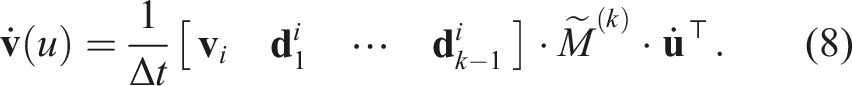
At this point, we’d like to note that, in this paper, the velocity spline is constructed from ego-centric velocity; therefore,
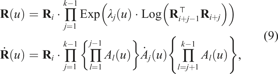
Analogous to the
4. Factor graph formulation
4.1. State definition and notation
In this work, we adopt a robot-centric state to embed the local gravity within the system state, which is defined as follows:
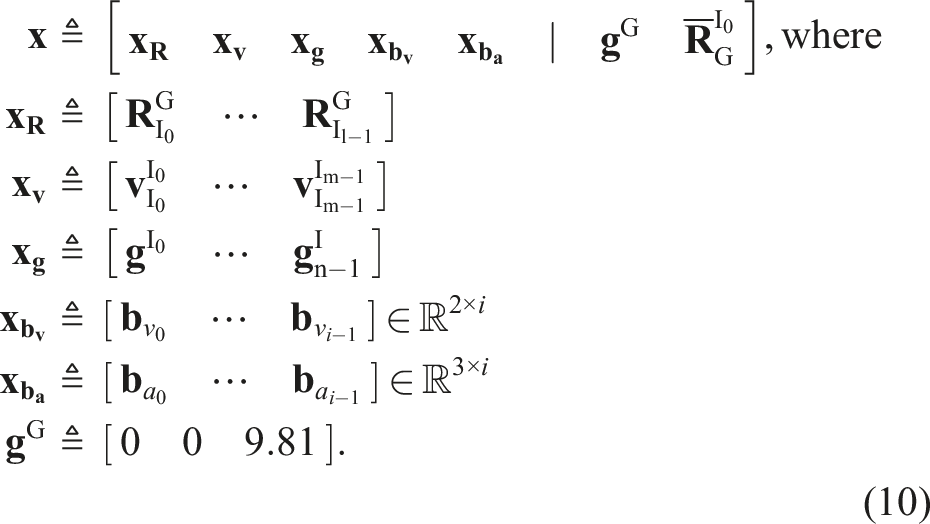
The system state
To achieve sensor fusion with multiple sensor modalities, our algorithm employs an incremental factor graph optimization framework that leverages B-splines for optimizing each control point. The factor graph used in our approach comprises an IMU factor, a velocity factor, and a gravity factor, collectively enabling robust and accurate state estimation.
4.2. IMU factor
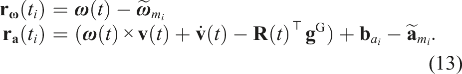
We employ two types of IMU factors: a gyroscope factor


where
4.3. Velocity factor
Our system leverages two sources of ego-centric velocity: a radar-derived velocity and a leg kinematics-based velocity. For the radar sensor, assuming that the j-th target point of radar measurements
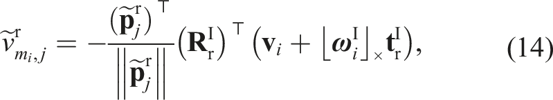
The translation between the robot’s body frame Comparison between body-centric and contact-centric leg locomotion of a single leg during the contact state. (a) On body-centric calculation, the end-effector position differs as time passes. Based on the contact information from the contact sensor positioned at every foot, every contact frame should remain static while the contact sensor is on. Therefore, using the forward kinematics, the ego-centric velocity of the robot base can be calculated as in (b).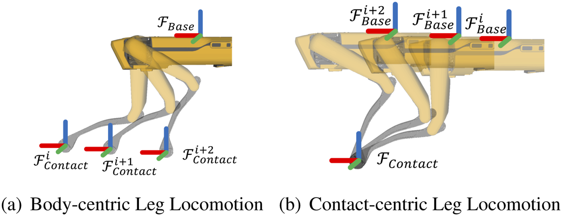


4.4. Gravity factor
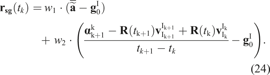
To mitigate the LiDAR-dependent and discrete-time sensor-fusion limitations of GaRLIO (Noh et al., 2025) and enable robust gravity estimation for legged robot platforms, we adopt a B-spline-based, velocity-aware gravity factor Soft 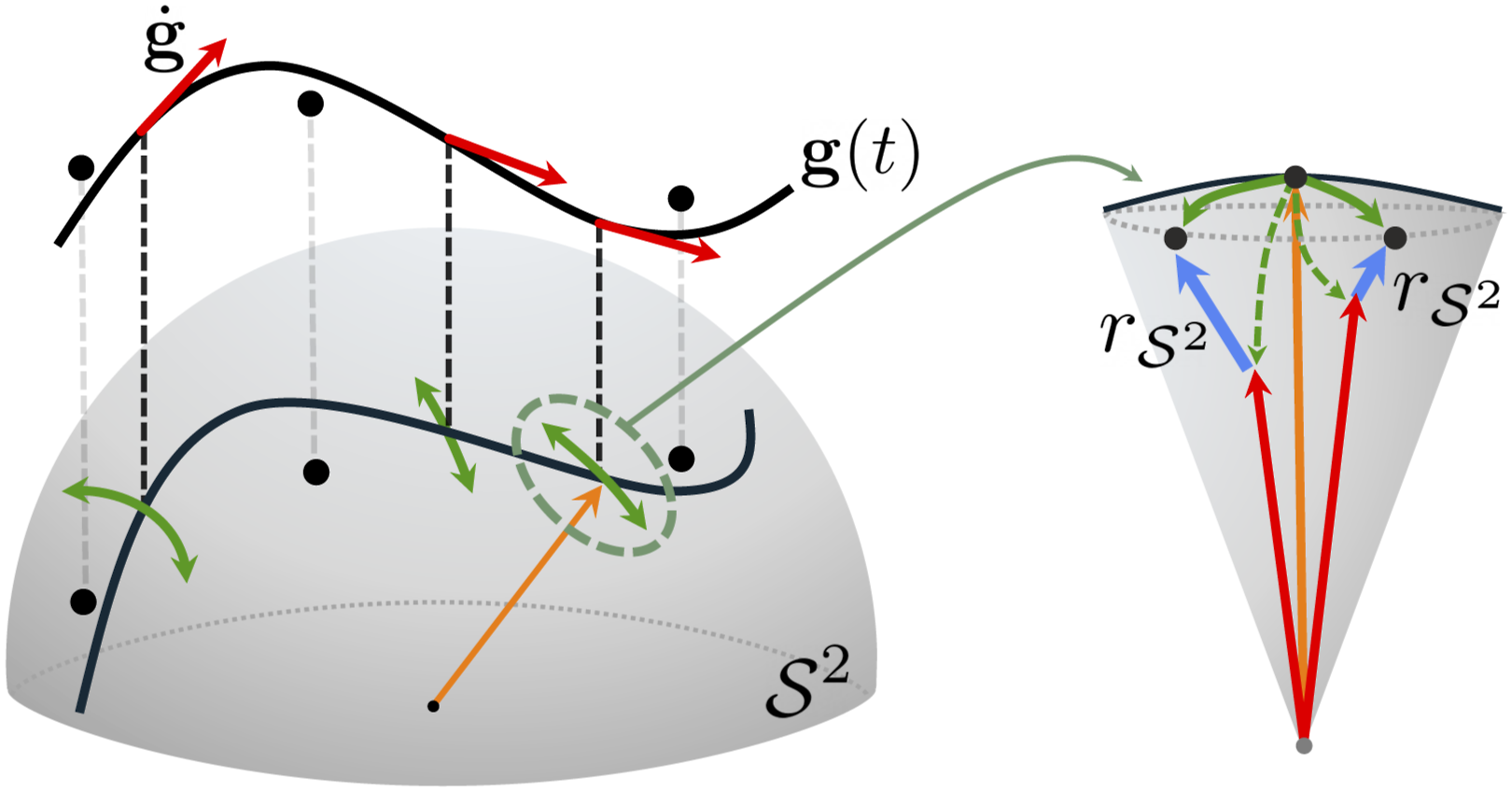

5. Continuous radar-leg-IMU fusion
Figure 4 illustrates the overall pipeline of GaRLILEO. The algorithm performs state estimation using three distinct splines representing SO(3) rotation, ego-velocity, and local gravity. In the initialization stage, the three splines and global gravity vector are recovered from the input data, similar to River (Chen et al., 2024). After transforming the data into a gravity-aligned coordinate frame, a tightly coupled incremental factor graph optimization is executed. Subsequently, a rotation refinement procedure using the estimated local gravity is applied to the marginalized older states, followed by odometry estimation through a dead reckoning approach. Overview pipeline of GaRLILEO.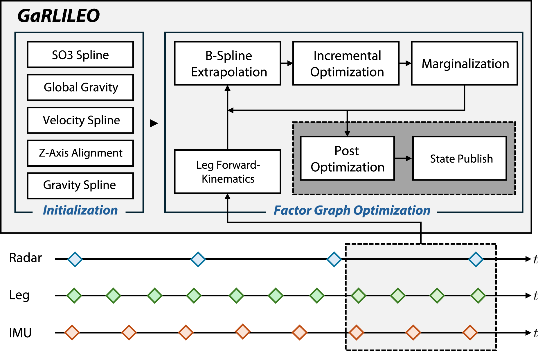
5.1. Initialization
5.1.1. SO(3) spline initialization
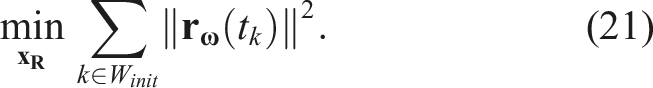
The initial SO(3) spline is constructed by applying the factor
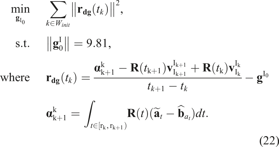
5.1.2. Global gravity initialization
Our method refines rotation by estimating local gravity and comparing it with global gravity. Therefore, accurate estimation of the global gravity reference is critical. For global gravity estimation, two different methods are popularly exploited: dynamic initialization and stationary initialization methods.
The first type is dynamic initialization introduced in River (Chen et al., 2024), which estimates global gravity using an initial SO(3) spline and radar measurements. Here, ego-velocities are computed from radar scans collected during the initialization phase, and then are converted into the global frame using the initial SO(3) spline. The global gravity is estimated using the following equation:
However, due to the highly nonlinear characteristics of IMU acceleration measurements from contact impact during legged robot locomotion, estimating global gravity dynamically at the radar frame rate using only the initial SO(3) spline results in inaccurate estimation. Therefore, a more stable method for estimating the global gravity is required on the legged robot UGV system.
Instead, we adopted a stationary initialization method for precise global gravity estimation. By computing the mean and variance of ego-velocities derived from accumulated radar scans during the initialization phase, the stationary condition can be determined using the following equation:

Under stationary conditions, the accelerometer measurements directly correspond to gravity. The mean of these measurements
Since this approach yields a more stable and accurate global gravity estimation compared to dynamic initialization on a legged robot, every sequence included in the dataset of this paper begins stationary, thereby enabling the use of static initialization.
5.1.3. Velocity spline initialization
The radar, IMU, and leg kinematics information are leveraged to construct the ego-centric velocity spline. During this process, velocity and acceleration biases are simultaneously initialized by solving the following least square (LSQ) problem:
5.1.4. Z-axis alignment with global gravity
The gravity vector has only 2-DoF observations, roll and pitch direction (Kubelka et al., 2022). Thus, to ensure optimization updates are confined to observable axes without explicit constraints, the coordinate frame is transformed by aligning its z-axis with the global gravity vector. Consequently, the SO(3) splines undergo the same coordinate transformation:
5.1.5. Gravity spline initialization
The final phase of initialization is on gravity spline. We initialize the gravity spline by recovering it through control points computed as

5.2. Factor graph optimization
5.2.1. Incremental optimization
Following initialization and spline recovery, incremental factor graph optimization is performed on the B-spline control points, tightly coupling IMU, leg kinematics, and radar measurements. When new control points are introduced, an equal number of the oldest points in the window are marginalized, and the information of the remaining non-marginalized control points is condensed into a prior factor and propagated to the next optimization window (Figure 5). The end time of the window is determined by the timestamp of the incoming radar topic, and optimization begins after the three B-splines are linearly extended and their control points appended. The factor graph comprises both gravity factors Factor Graph Overview. At each iteration, the number of control points marginalized (gray) equals the number newly added in the preceding window (red); the remaining control points are carried forward as a prior factor for the next solve (blue). The marginalized control points (gray) are then subjected to a post-optimization stage that refines the SO(3) spline.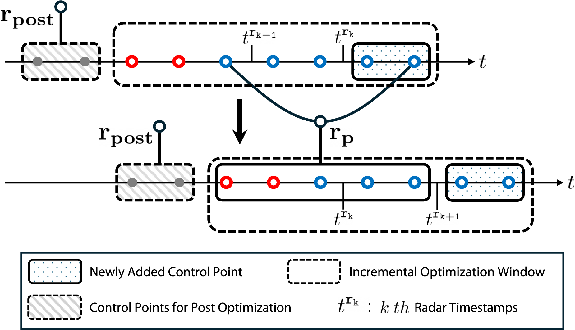
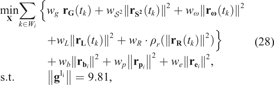
Dependencies between sensor measurements and each spline during the optimization of (28) are illustrated in Figure 6. To mitigate the contact-induced noise of IMU acceleration degrading the velocity spline, we decoupled the velocity spline from IMU. Instead, we leverage continuous-time ego-centric velocity spline generated from SoC radar and leg kinematics measurements, improving the robustness of local gravity estimation compared with prior methods. Within each window W
i
, the biases Relationship between sensor data and splines during incremental optimization. Gray-shaded boxes indicate sensor measurements active within the sliding optimization window; colored lines denote inter-spline and measurement-spline dependencies. In GaRLILEO, velocity is decoupled from the IMU, constructing a continuous-time ego-velocity spline from radar and leg kinematics measurements. This decoupling is particularly advantageous for legged robots, where ground contact induces noisy accelerations on IMU.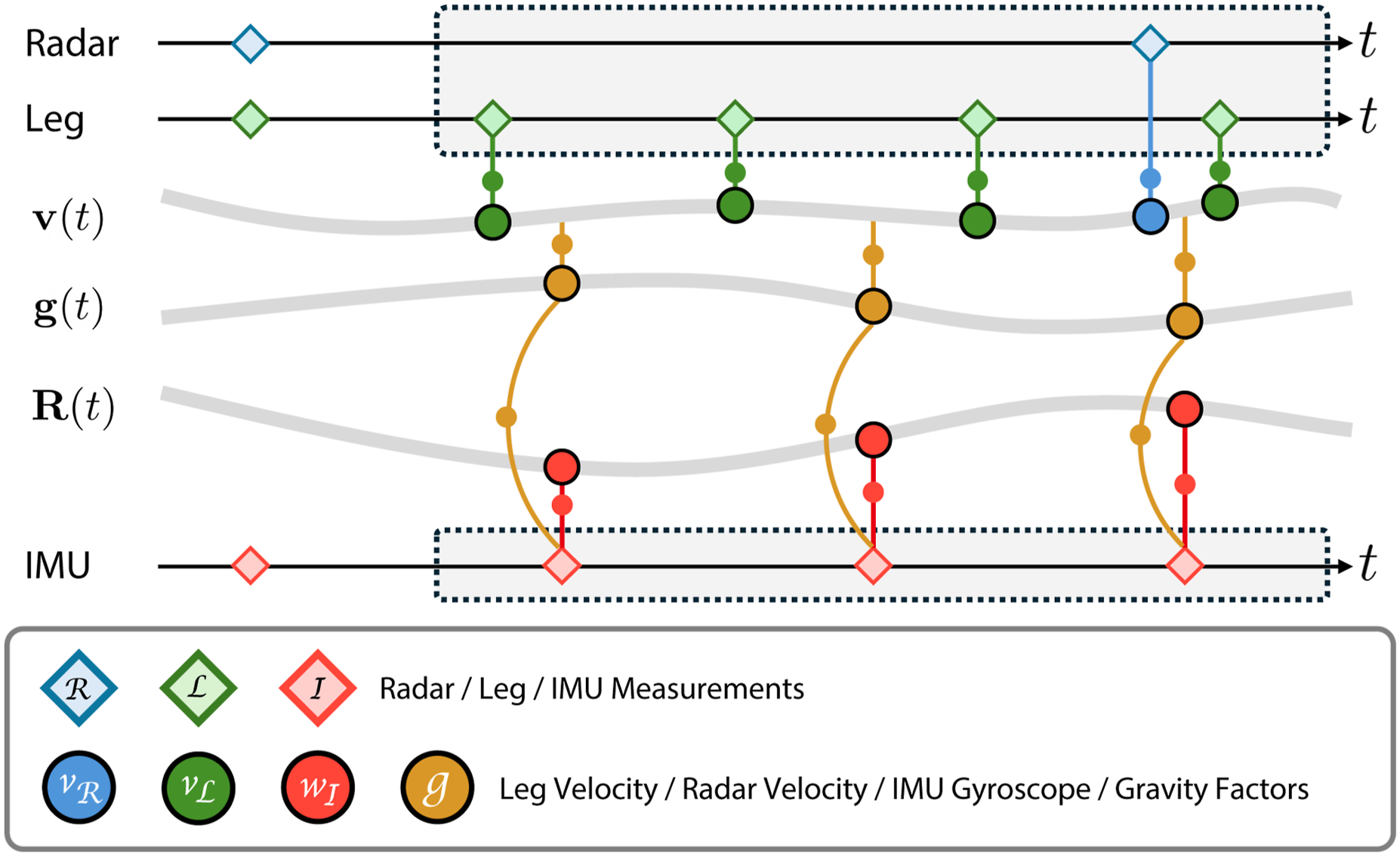
5.2.2. Marginalization
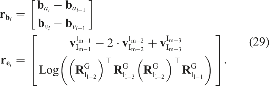
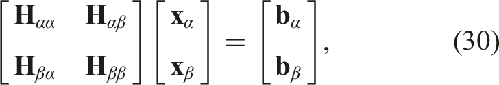
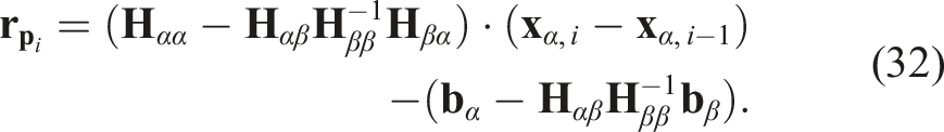
At each optimization step, we marginalize out the states and measurements that moved outside of the sliding window, summarizing them into a single prior factor. By reusing historical constraints in this condensed form, the estimator retains observability of active variables while bounding the graph size, achieving computational efficiency for real-time performance. By linearizing all factors about the current best estimate of the i-th window, we obtain an equation as follows:

5.2.3. Post optimization
After incorporating the optimized local gravity state from (28), we refine the rotation states of the relevant static control points. This procedure is applied to the control points marginalized in the previous optimization window, as shown in Figure 5. In this step, we update only the rotation states while keeping others fixed:
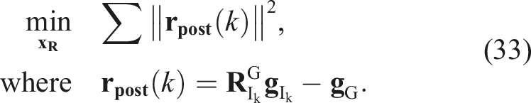
Since the global z-axis is aligned with gravity, the above equation provides information only about roll and pitch but not yaw; rotation about the gravity axis remains unobservable. After the post-optimization step, the robot’s pose is estimated using dead reckoning based on the optimized states. The ego-centric velocity is first transformed into the global frame, and subsequently, the robot position is computed using the following equation:
6. Radar-leg-IMU dataset
6.1. System configuration
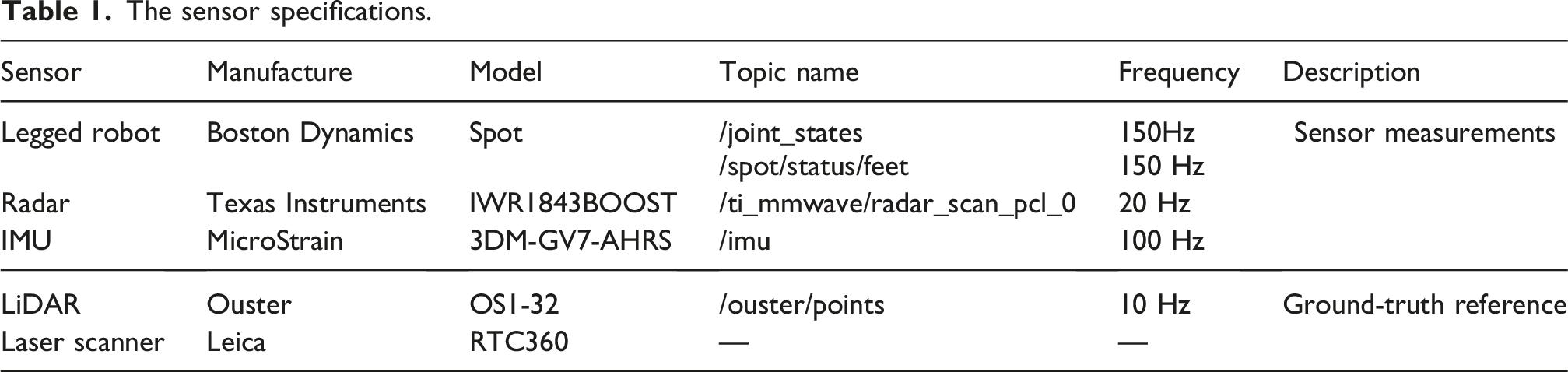
The overall sensor configuration and the coordinate frames of each sensor are illustrated in Figure 7, while detailed specifications for each sensor are provided in Table 1. Two different data acquisition setups are employed in this work, both built on Spot, a quadrupedal robot from Boston Dynamics, which provides joint encoder and contact sensor data at 150 Hz. An IWR1843BOOST mmWave radar module captures 4D radar point clouds with a maximum range of 11 m and a range resolution of 4.8 cm, while a 3DM-GV7-AHRS IMU from Microstrain operates at 100 Hz to provide inertial measurements including onboard AHRS orientation measurement. Both systems share the same radar and IMU sensor models. SNU and RAI sensor system deployment. Both systems include the same TI-mmWave radar, MicroStrain IMU, and Boston Dynamics Spot quadrupedal robot, but are attached with different extrinsics. The sensor specifications.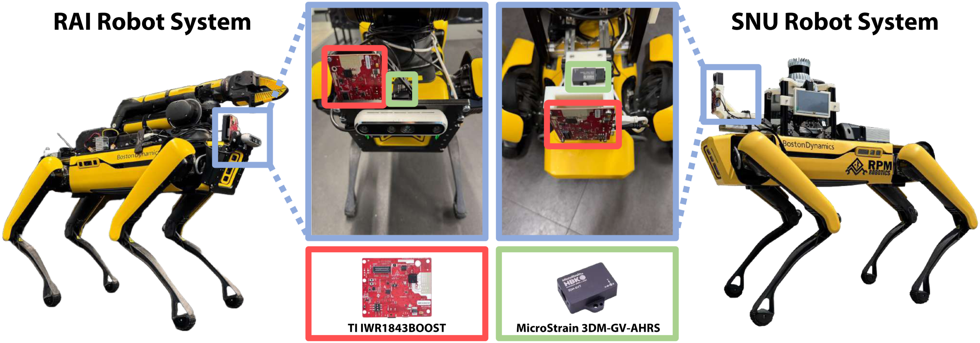
6.1.1. SNU system
The SNU system, used for experiments at Seoul National University, collects data in diverse conditions, including both indoor and outdoor environments. To obtain a baseline trajectory, an OS1-32 LiDAR (maximum range 150 m) is mounted, and a TLS-generated map is used as ground-truth reference (see Section §6.4). Data acquisition and logging are performed onboard using the Spot CORE, equipped with an Intel 8th Gen i5 processor and 16 GB of DDR4 RAM.
6.1.2. RAI system
The RAI system, used for experiments at the Robotics and AI Institute, operates entirely within an indoor motion capture environment, providing a controlled experimental setup. While sharing the radar and IMU configurations of the SNU system, the LiDAR is omitted, and ground truth is obtained from the motion capture system. Data is acquired and logged onboard with an NVIDIA Jetson AGX Orin, including a 12-core Arm Cortex-v8.2 CPU and 64 GB of LPDDR5 RAM.
6.2. Details of each sequence
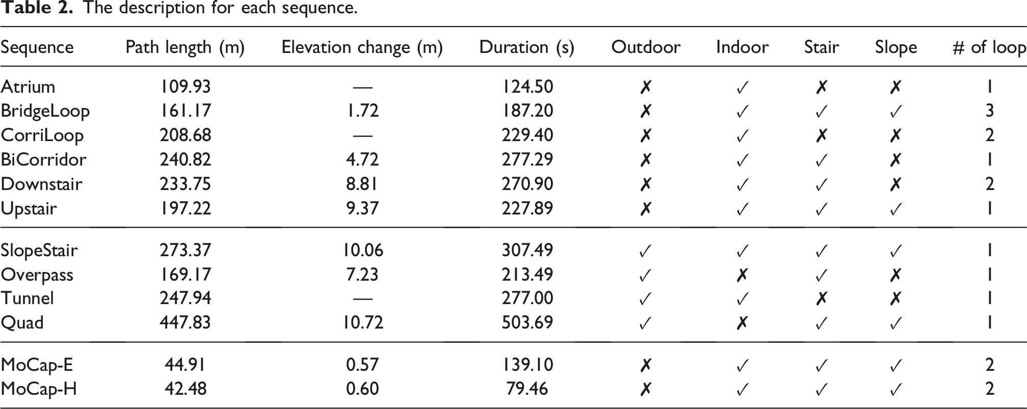
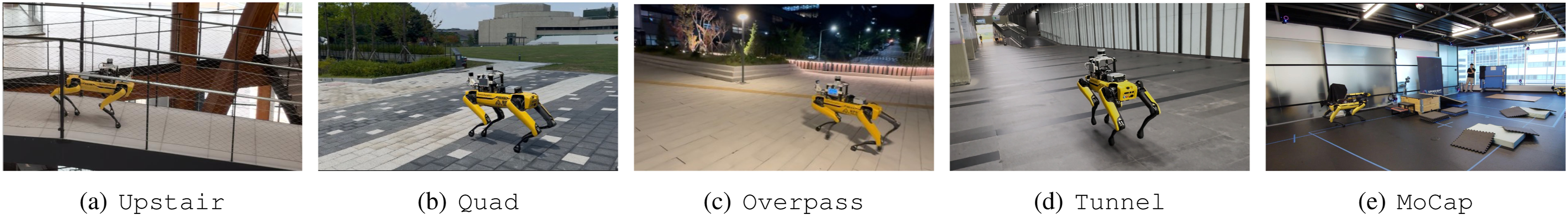
An overview of the 12 sequences is given in Table 2, and their environments are illustrated in Figure 8; details of each sequence are as follows: • Atrium: A large flat floor indoor atrium with floor-to-ceiling glass and a high ceiling, where the expansive open floor and long glass facades induce strong specular reflections, multipath, and low parallax on radar sensor. • BridgeLoop: An indoor sequence with three repetitions that traverses pedestrian bridges and short stair segments around an open atrium, stressing robustness in wide, low-parallax spaces. • CorriLoop: A narrow, rectangular indoor corridor traversed twice; long straight segments with repeating doors/walls and a glossy floor create perceptual aliasing, while four sharp 90° turns stress turn handling and loop consistency. • BiCorridor: A two-level corridor running in the same building as • Downstair: A multi-floor indoor sequence that starts on the second level with a long rectangular loop, descends one flight to traverse an extended straight corridor, then descends again to finish with a smaller rectangular loop. Wide, glossy hallways and two prolonged downward staircases stress perception during extended descent, floor-to-floor transitions, and low-parallax segments. • Upstair: An indoor ascent sequence in the same building as • SlopeStair: A mixed indoor–outdoor traverse with a long downhill ramp, multiple upstair flights, and doorway/corridor transitions, stressing robustness to large elevation changes, lighting shifts, and abrupt structural/surface variations. • Overpass: This sequence takes place on outdoor stairs and a pedestrian overpass, with lamps and reflective paving. It stresses robustness to open-air transitions and repeated elevation changes across steps, ramps, and long sidewalk segments. • Tunnel: This sequence traverses a long, semi-open tunnel lined with glass façades and repetitive concrete pillars. The path includes gentle ramps and a tight U-turn, stressing robustness under feature-degenerate geometry and illumination changes. • Quad: This sequence traverses an outdoor campus quad with broad paved plazas, tiled walkways, curbs, and stairs. It stresses robustness to feature-sparse open areas and repetitive textures while handling stair climbing, ramps, and outdoor slopes. • MoCap-E: This sequence has two loops in the indoor Motion Capture (MoCap) room, each including a short stair–slope vertical motion zone and a cushion zone with two soft cushions that disturb leg odometry. In the second loop, a folded box at the slippery zone is deliberately dragged, breaking the assumption of a stationary floor and causing a marked discrepancy between leg kinematics and other sensors. • MoCap-H: This sequence shares the same layout as The description for each sequence. Environmental examples of the acquired sequences. Diverse environments are included in each sequence to consider various situations that the quadrupedal robot may encounter in a real-world mission. (a)
6.3. Extrinsic calibration of sensor systems
Extrinsic calibration between Spot, radar, and IMU is required for accurate odometry estimation. On both sensor systems, we leveraged the CAD model of each system to acquire the exact extrinsic parameters between the sensors. As included in Figure 7, the radar attached to the RAI system is slightly biased to the right side of the robot, and the IMU is attached perpendicularly compared with the SNU system. For more detailed information about the extrinsic calibration parameter, please refer to the project homepage.
6.4. Ground truth trajectory generation
6.4.1. SNU sequences
Accurate 6-DoF ground truth poses are essential for evaluating various robotic tasks, including state estimation and SLAM. Unlike previous studies, our deployments span both indoor and outdoor environments over several hundred meters, requiring millimeter-level precision. These stringent requirements render traditional ground truth sources, such as LiDAR-IMU-based references (Jung et al., 2024) and RTK-GNSS systems (Barnes et al., 2020; Geiger et al., 2013; Kim et al., 2025a), unsuitable. While MoCap systems can provide high-frequency and high-precision pose estimates, their limited workspace makes them impractical for large-scale deployments (Doer and Trommer, 2021). Some prior works (Tranzatto et al., 2022b) utilize survey-grade maps as ground truth references by performing scan-to-map matching of deskewed LiDAR points using synchronized inertial and ranging sensors. However, for legged robots, continuous dynamic motion during data acquisition significantly degrades LiDAR deskewing and motion estimation accuracy.
To address this, we adopt the approach proposed in Hu et al. (2024), which combines FAST-LIO2 (Xu et al., 2022) odometry and loop closure factors with a degeneration-aware map factor derived from dense prior maps. As illustrated in Figure 9, prior maps are collected using a Leica RTC360. This graph-based formulation enables accurate pose estimation even in degenerate and stationary conditions, thereby providing reliable ground truth for our evaluation. Examples of ground truth TLS map on SNU sequences. Leveraged for generating ground truth trajectory. (a) Indoor Sequences. Left: 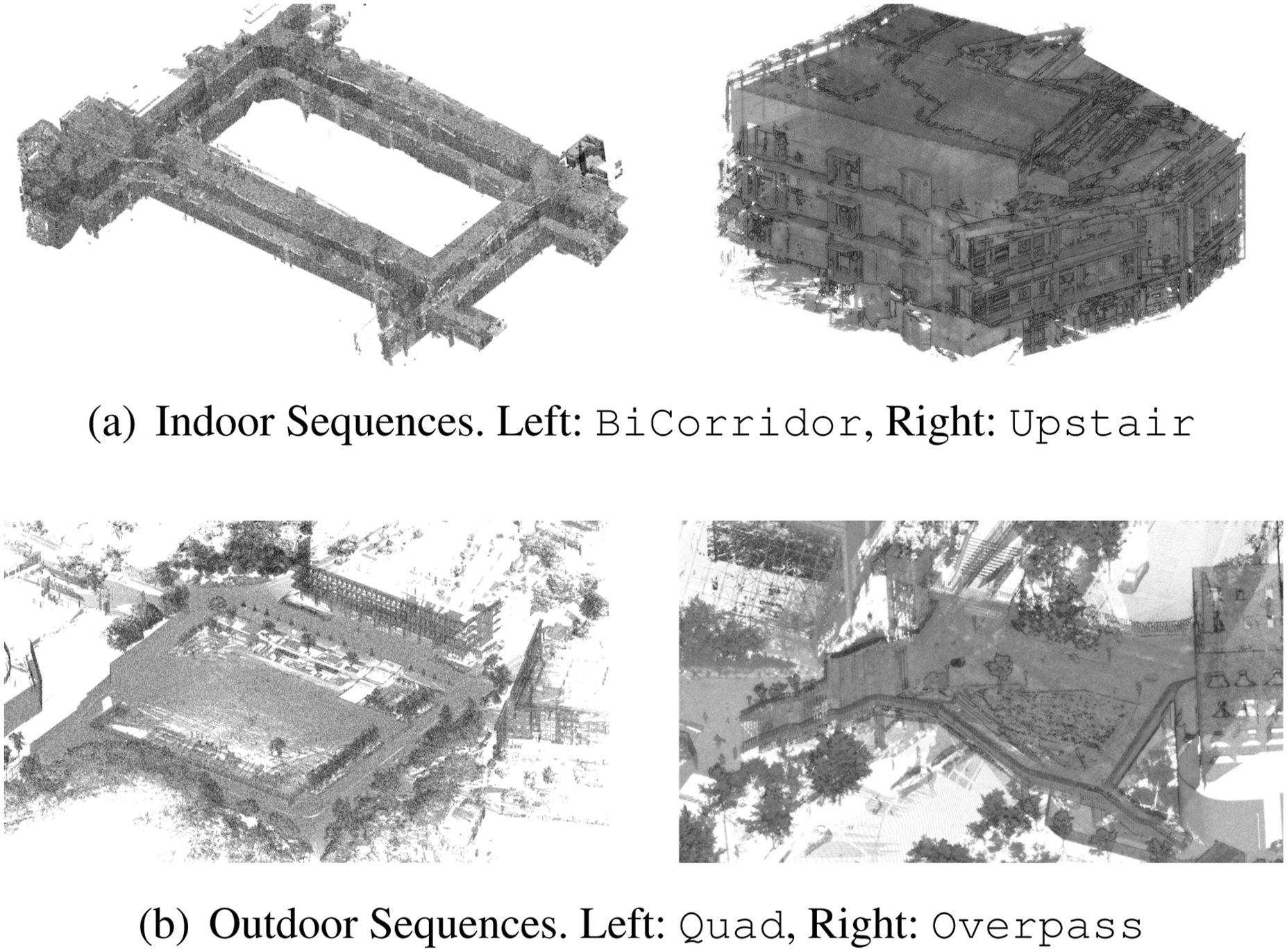
Because this ground truth framework leverages FAST-LIO2 (Xu et al., 2022), a tightly coupled LiDAR-IMU SLAM as an odometry front-end, precise extrinsic calibration between those two sensors
6.4.2 RAI sequences
For MoCap sequences acquired using the RAI sensor system, we utilized the MoCap system to obtain a highly precise ground truth trajectory. As these sequences were collected exclusively in a controlled indoor environment, the MoCap odometry could be reliably used as reference. The experiment was conducted in a 13.5 m × 5 m × 3 m motion capture room equipped with 20 Vicon Valkyrie VK 16 cameras, ensuring complete coverage of the space. The system streamed motion capture data at 120 Hz using Vicon Tracker 4.3 software.
7. Experiment results
In this section, we evaluate the performance of GaRLILEO against SOTA odometry algorithms that utilize SoC radar, IMU, and leg kinematics. The experiments are conducted on a self-collected real-world dataset.
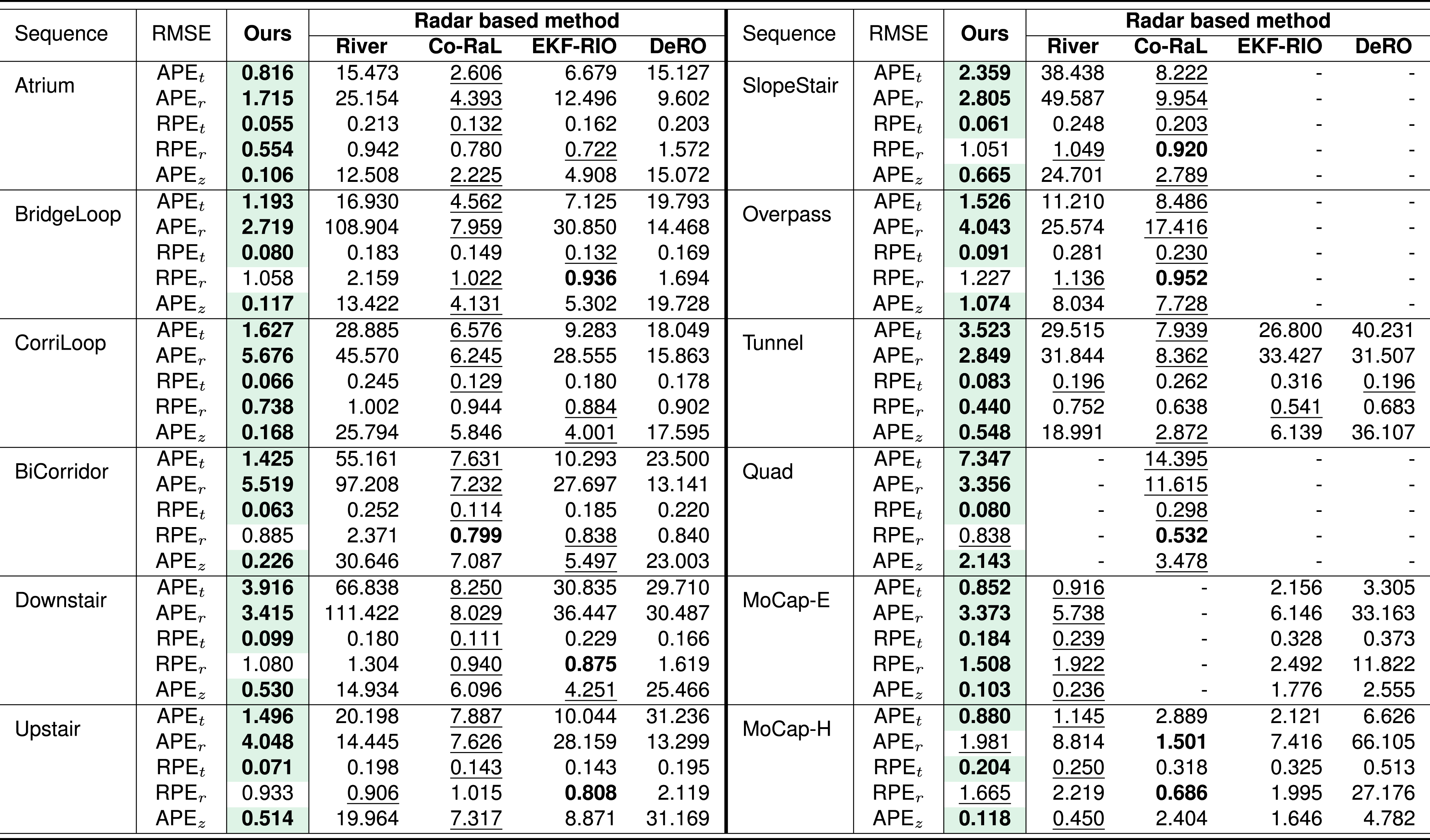
Odometry accuracy is assessed using the root mean square error (RMSE) of absolute pose error (APE) and relative pose error (RPE), each decomposed into translational and rotational components. The units are as follows: APE t (m), APE r (°), RPE t (m/m), and RPE r (°/m). To specifically evaluate vertical drift in odometry, we report the z-axis APE (APE z ). All evaluations are performed using the Evo Trajectory Evaluator (Grupp, 2017), a widely adopted open-source toolkit for odometry benchmarking in robotics.
The comparative analysis is organized by the baselines’ sensor configurations, while GaRLILEO is evaluated in its full configuration to report system-level performance, that is, the benefit of fusing leg kinematics, radar, and IMU. First, we compare GaRLILEO against recent SoC radar-IMU odometry methods, including Co-RaL (Jung et al., 2024), which additionally integrates the leg kinematics velocity factor. Next, we also evaluate GaRLILEO against open-source leg kinematics-IMU fusion odometry methods. Every parameter is adopted from the official implementation, except that the robot-specific parameters of legged robots are modified based on the official Unified Robot Description Format (URDF) file of Boston Dynamics SPOT. Detailed descriptions of the baseline algorithms and comprehensive evaluation results are provided in the following subsections.
After comparing GaRLILEO directly with the baselines, we conducted detailed ablation studies on the modules of GaRLILEO. Specifically, we analyzed the complementary effect between radar and leg kinematics, the contribution of gravity factors to both local gravity vector estimation and odometry, and the impact of the velocity bias term.
7.1. Radar-IMU odometry comparison
In this subsection, we compare the performance of GaRLILEO with that of five recent SoC radar-inertial odometry (RIO) methods. The baseline methods are listed as follows: • • • •
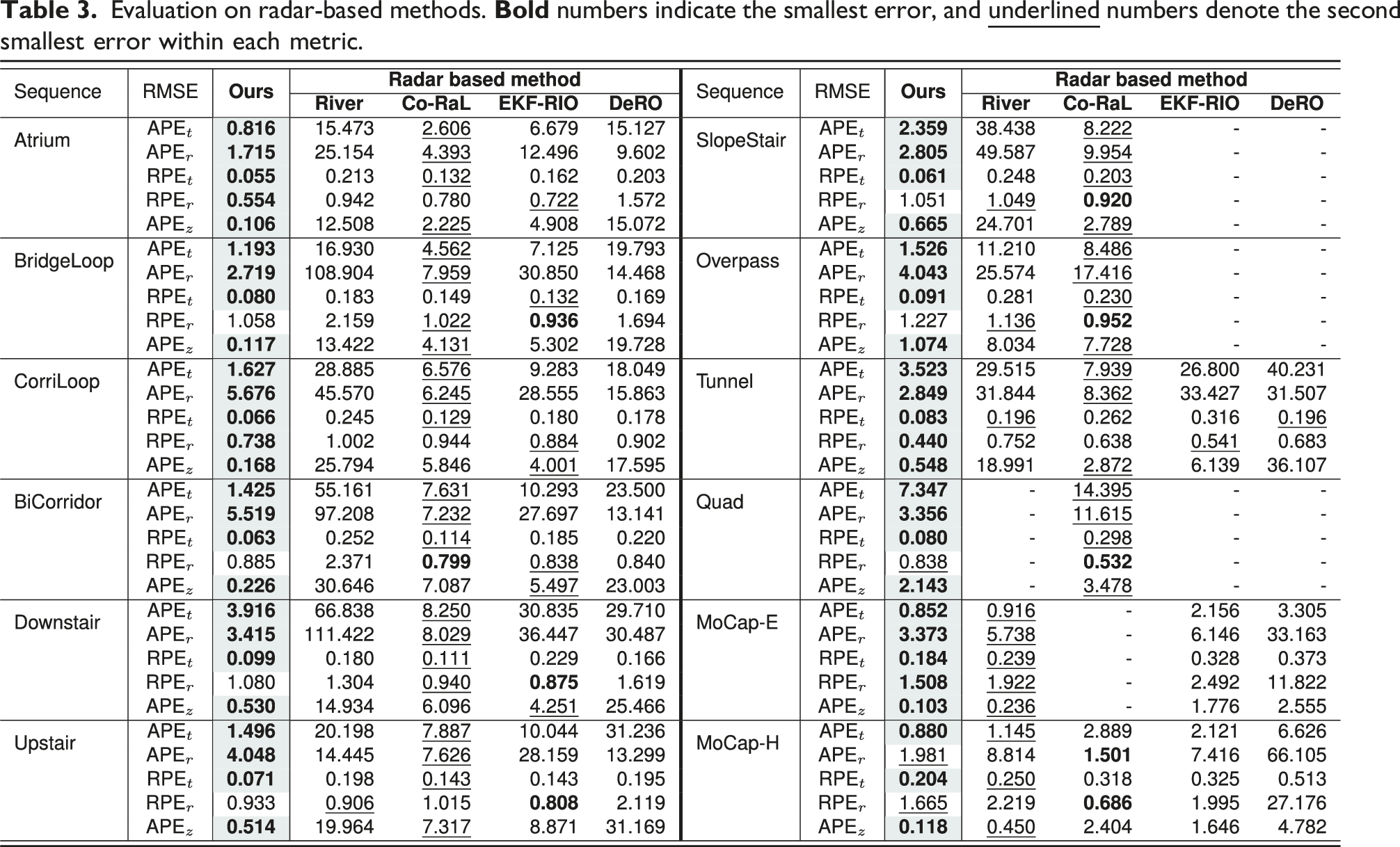
Evaluation on radar-based methods.
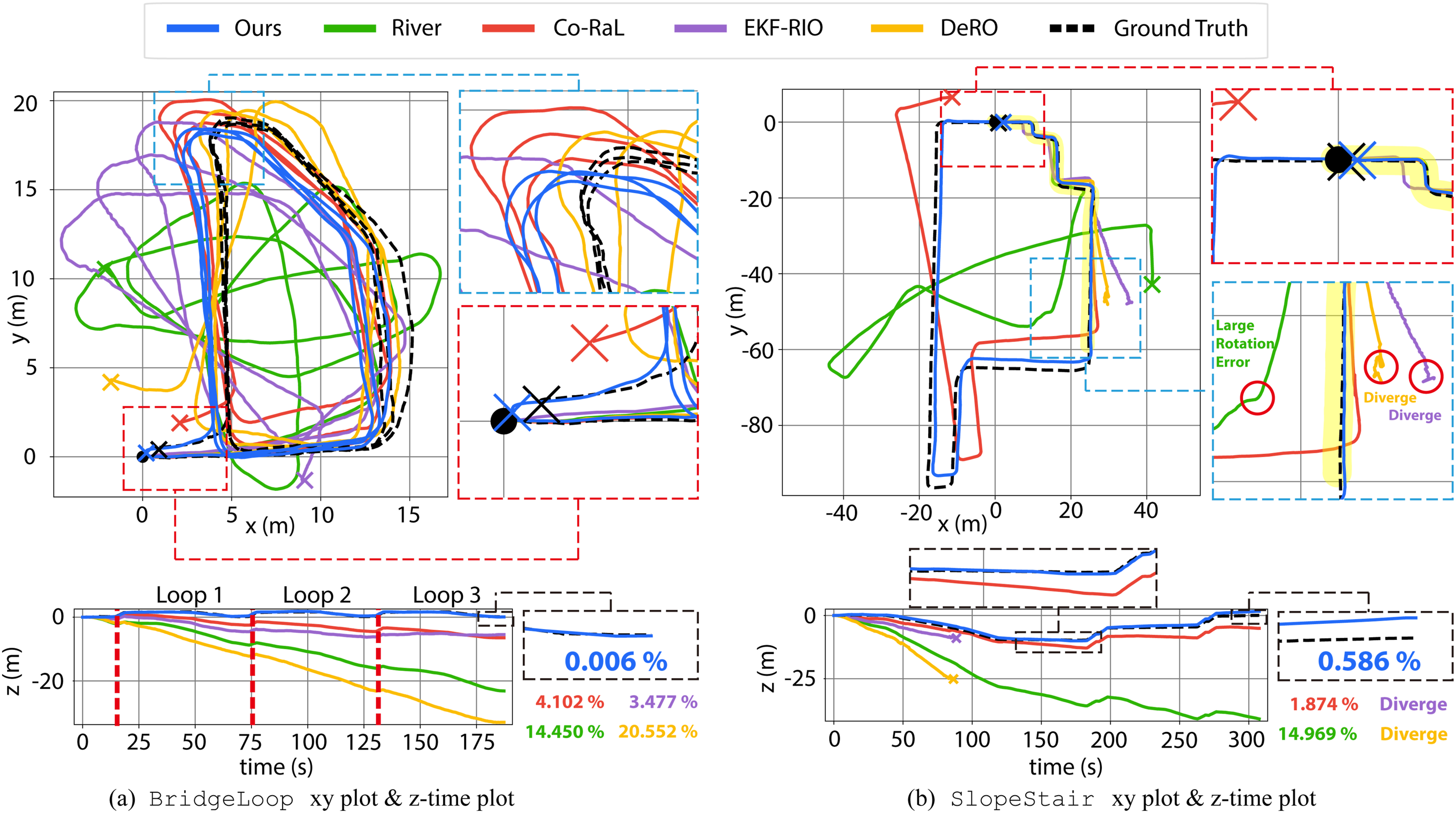
Radar–Inertial baseline odometry results on the (a)
7.1.1. Atrium
We first evaluate methods on the
7.1.2. BridgeLoop
We next assess the
7.1.3. CorriLoop
The
7.1.4. BiCorridor
The
7.1.5. Downstair
In the
7.1.6. Upstair
The
7.1.7. SlopeStair
As the system moves from indoors to outdoors and back in during this sequence, severe drift at the corner before re-entry causes EKF-RIO and DeRO to diverge. This highlights the limitations of SoC radar-IMU-only systems during indoor/outdoor transitions. Although River converges, their vertical errors (APE z ) remain significantly higher than those of methods incorporating leg kinematics, highlighting the importance of kinematics sensing for stable and accurate odometry. Co-RaL, fusing leg kinematics with radar-IMU data, achieves the second-best performance across most metrics, demonstrating the benefits of multi-modal integration. Finally, GaRLILEO delivers the most accurate odometry overall, achieving sub-meter-level vertical accuracy.
7.1.8. Overpass
In the
7.1.9. Tunnel
In the Tunnel sequence, which features a long passage with a sharp U-turn, GaRLILEO maintains sub-meter APEz and achieves the lowest error on every metric. Co-RaL, benefiting from radar–leg kinematics fusion, ranks second. River and DeRO exhibit severe vertical drift due to contact impacts and limited observability. EKF-RIO shows less drift than these methods, but still larger vertical errors than leg kinematics-fused methods.
7.1.10. Quad
The Quad sequence, the longest and most challenging dataset, includes stairs, slopes, and substantial elevation changes. Frequent contact drift, multiple dynamic objects, outdoor stairs and slopes, and a reduced number of radar points make accurate pose estimation particularly difficult. River, EKF-RIO, and DeRO fail to converge due to sparse radar returns. Due to its factor graph framework that adaptively relies on the more reliable sensor modality, Co-RaL succeeds in converging and even outperforms GaRLILEO on RPEr. Nevertheless, GaRLILEO achieves a notably lower error on all other metrics through precise local gravity estimation, while exhibiting slightly higher but competitive RPEr compared to Co-RaL. These results highlight that GaRLILEO consistently provides robust and accurate pose estimation across diverse environments, owing to its local gravity model.
7.1.11. MoCap-E
Both MoCap sequences include two challenging test scenarios: (i) a slippery zone with a backward-moving floor in the second loop and (ii) a cushion zone included in both loops. These environments are designed to degrade leg odometry. In the slippery zone, as the contact frame continuously moves, leg kinematics produce erroneous horizontal velocity estimates. In the cushion zone, where the contact frame moves downward while the contact sensor remains active, leg kinematics yield incorrect vertical velocity estimates.
In
7.1.12. MoCap-H
In
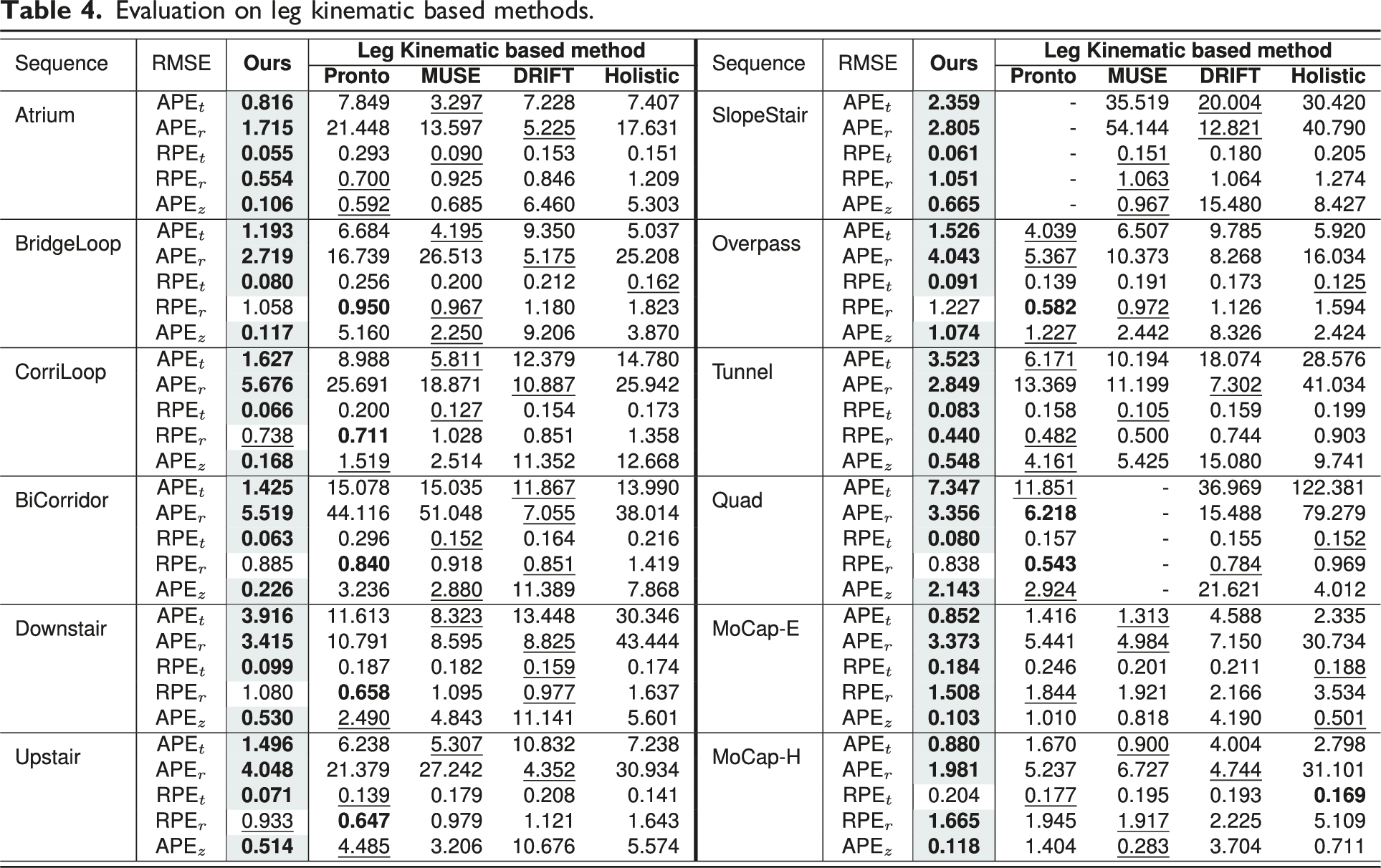
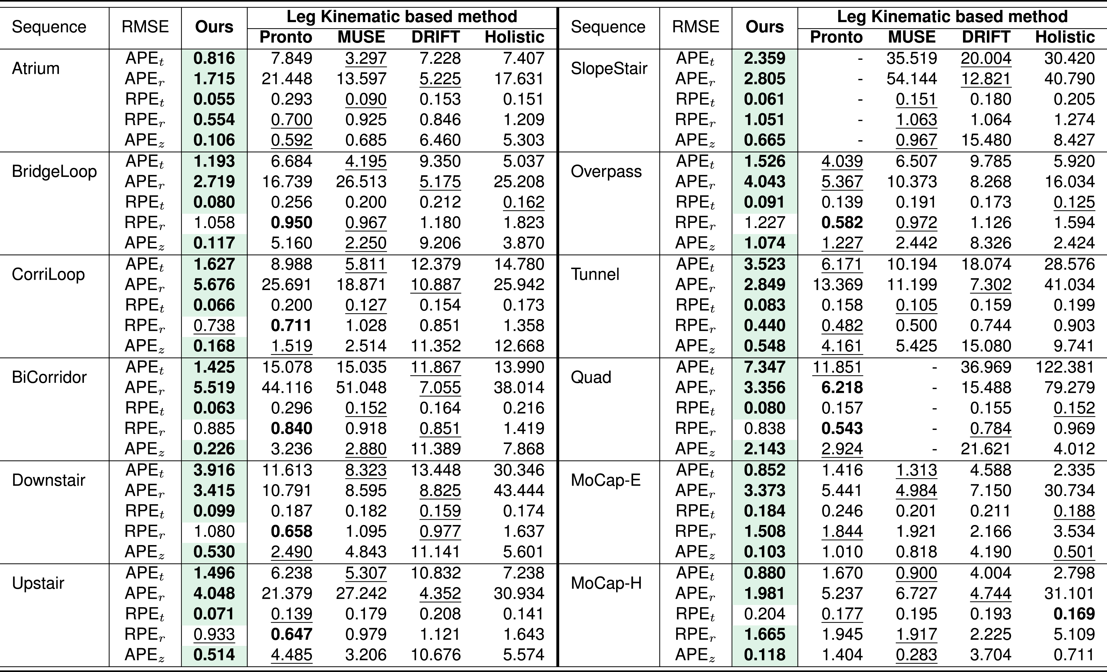
7.2. Leg kinematics odometry comparison
In this subsection, we compare GaRLILEO against four proprioceptive odometry methods that fuse IMU and leg kinematics sensors, including leg joint encoders and contact sensors. The baseline methods are described as follows: • • • •
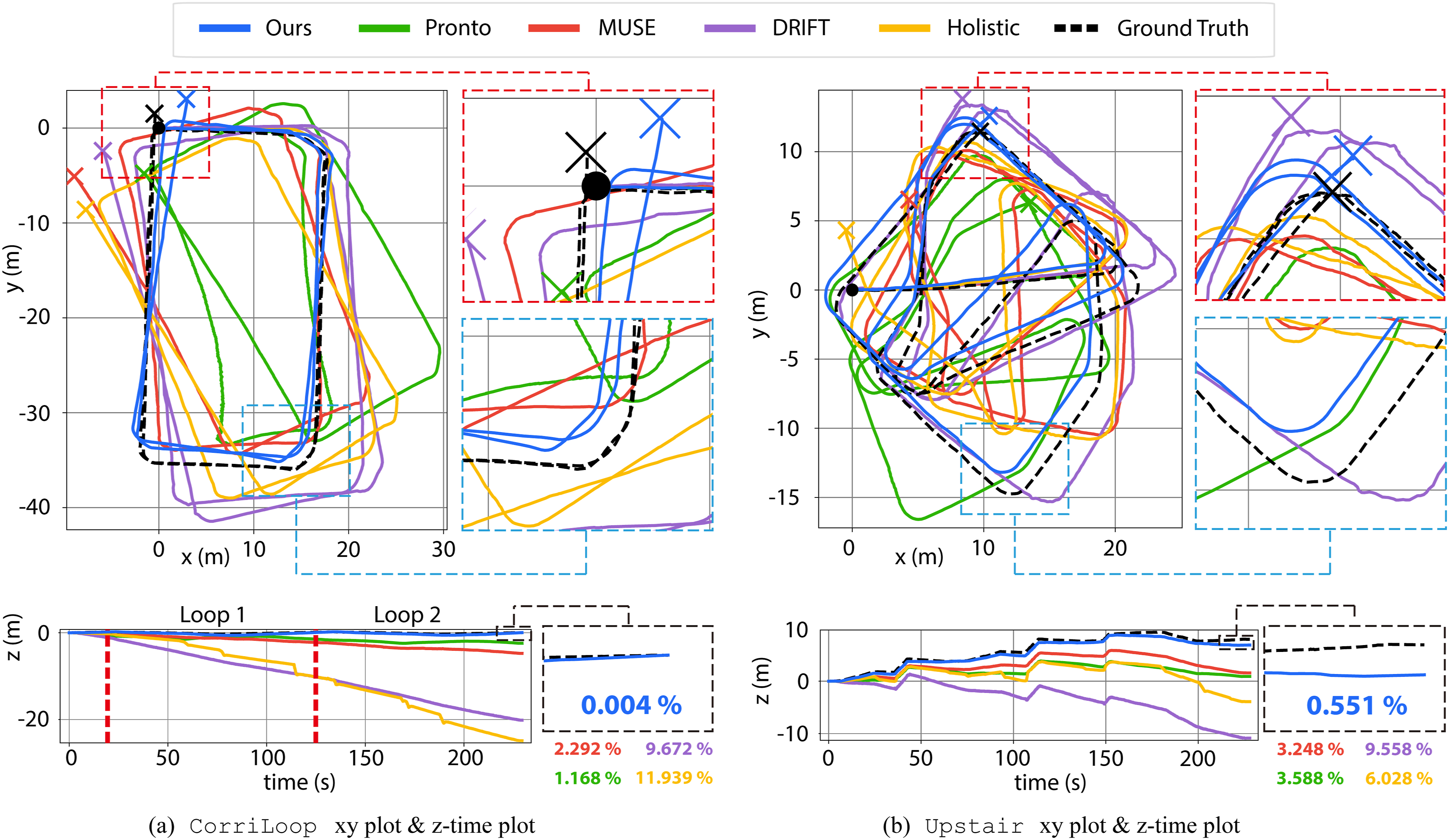
This subsection evaluates the odometry accuracy of proprioceptive methods, with a focus on their performance in diverse environments. Table 4 presents quantitative results for APE and RPE metrics, while Figure 11 shows qualitative results for two sequences. GaRLILEO consistently achieves the most accurate odometry estimates across most sequences, primarily due to its integration of SoC radar-derived ego-velocity, which effectively mitigates the challenges posed by leg contact drift.
7.2.1. Atrium
Pronto, Drift, and Holistic achieve similar APE t , while Pronto, through weighted averaging of leg kinematics velocities, attains the most accurate APE z , demonstrating the reliability of leg kinematics in this environment. MUSE, which incorporates a slip detection algorithm, achieves a comparable APE z to Pronto and even lower APE t , indicating the presence of slip or drift in the contact frame even in low-dynamic indoor settings. GaRLILEO achieves the most accurate overall odometry, presenting the lowest error on every metric.
7.2.2. BridgeLoop and CorriLoop
The
7.2.3. BiCorridor
In the
7.2.4. Downstair and Upstair
The
7.2.5. SlopeStair Sequence
In the
7.2.6.
In the
7.2.7. Tunnel
In the
7.2.8.
The
7.2.9. MoCap-E and MoCap-H
Evaluation on leg kinematic based methods.
Leg-kinematics baseline odometry results on the (a)
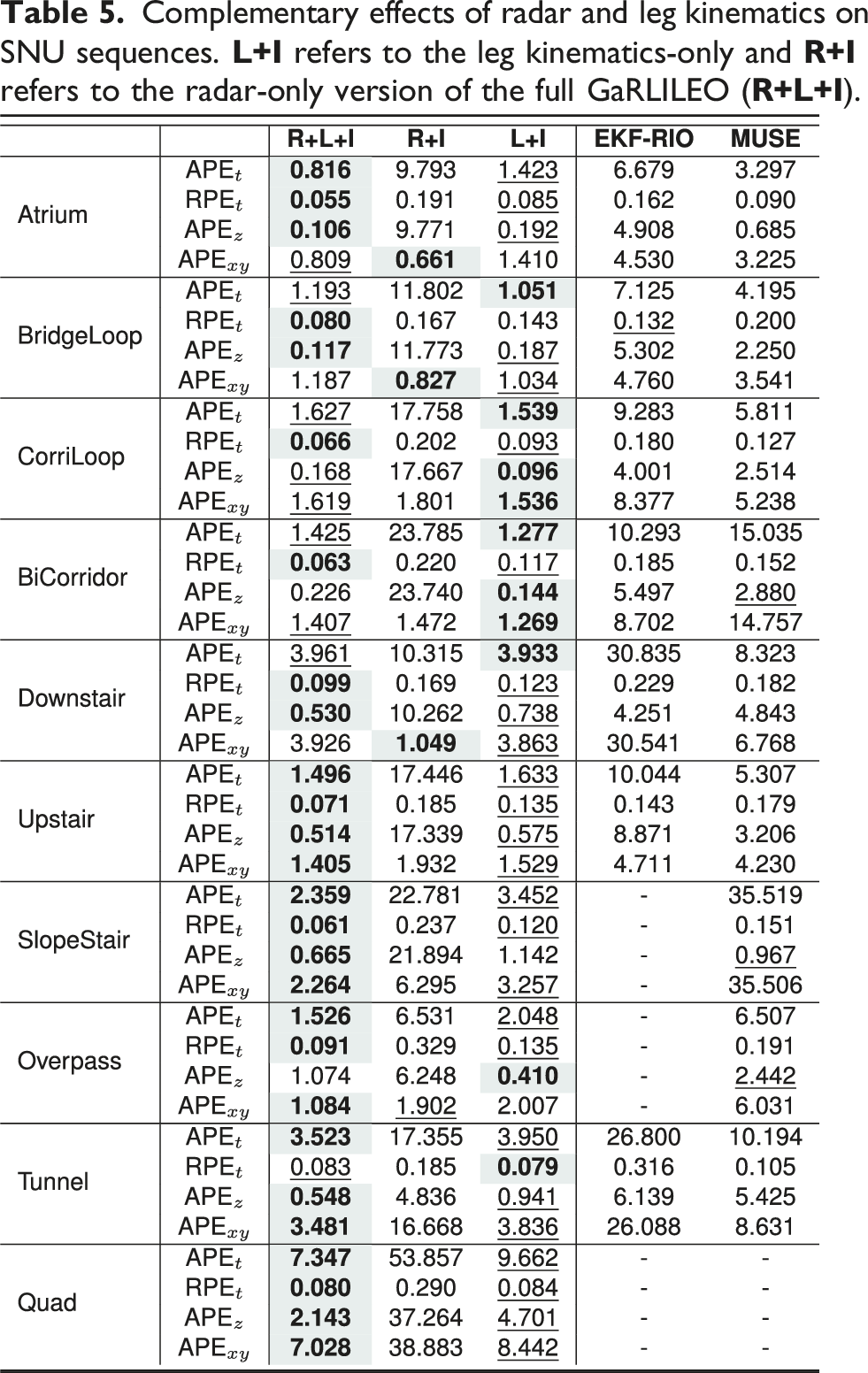
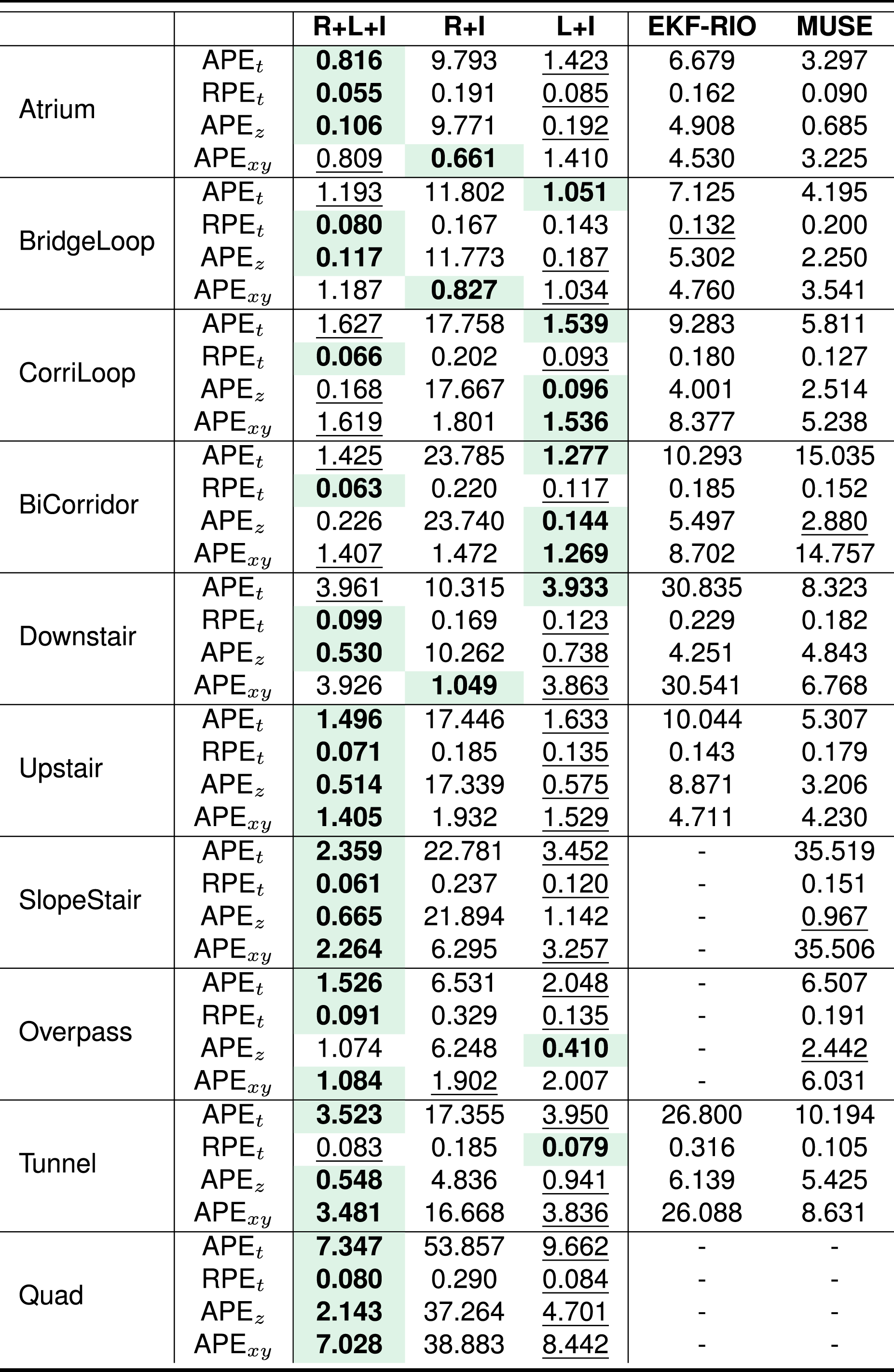
7.3. Complementary effects of radar and leg kinematics
To analyze the complementary roles of radar and leg kinematics, we compare three GaRLILEO configurations: the full system
7.3.1. SNU Sequences
Table 5 summarizes the results on the SNU sequences. Overall, the sensor-subset variants
Regarding the modality-specific comparisons,
7.3.2. RAI Sequences
Complementary effects of radar and leg kinematics on SNU sequences.
On v
x
-time and v
z
-time Velocity Error (difference from ground truth) in the xy plot and z-time plot of Complementary effects of radar and leg kinematic on RAI sequences. 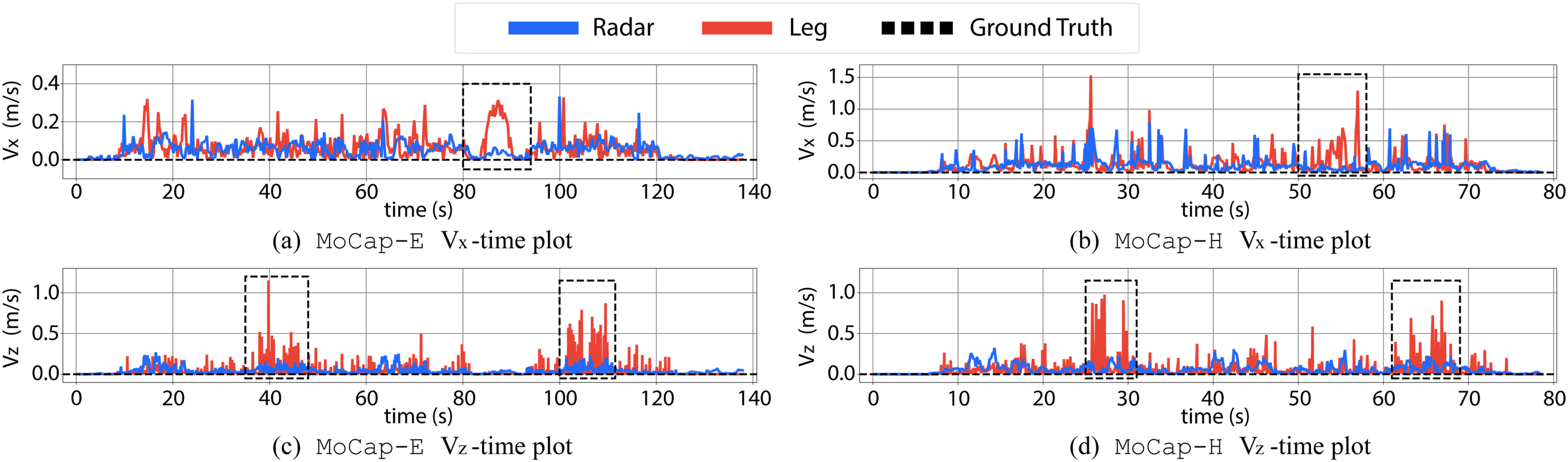
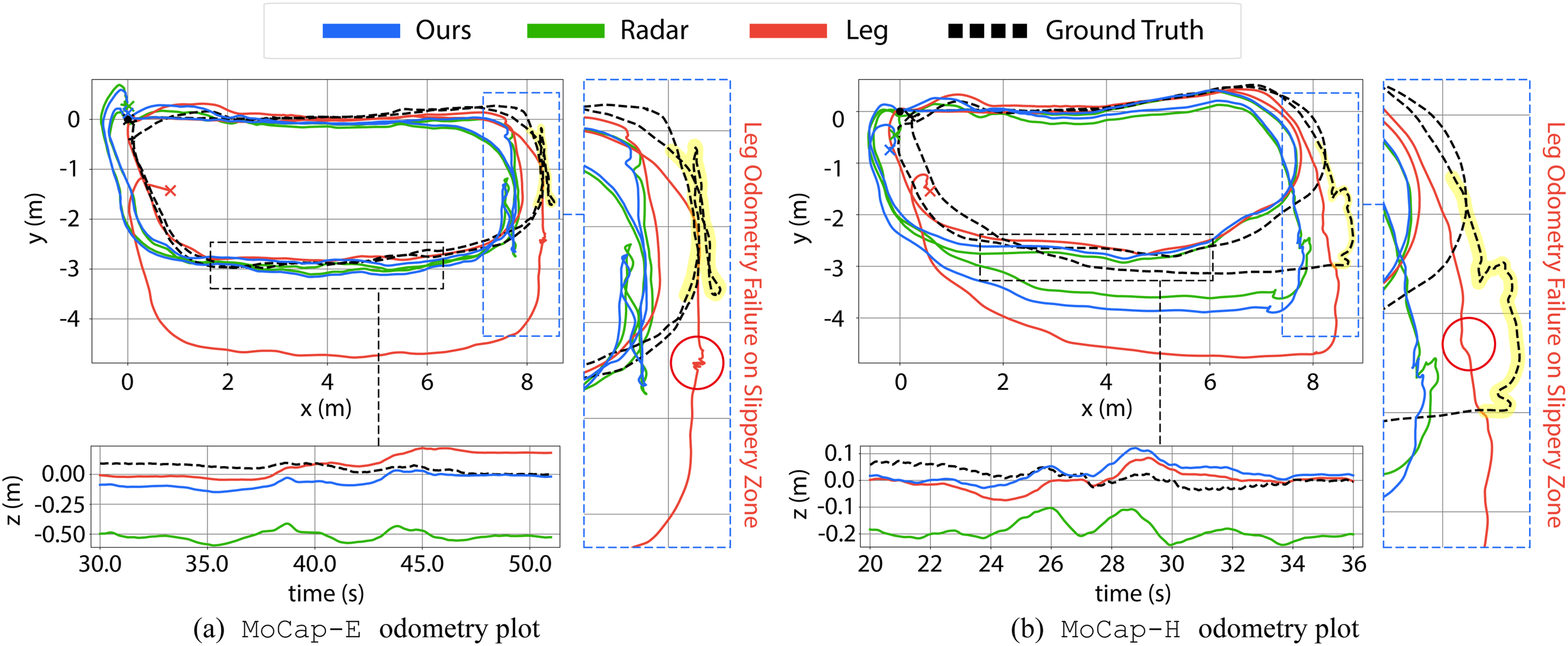
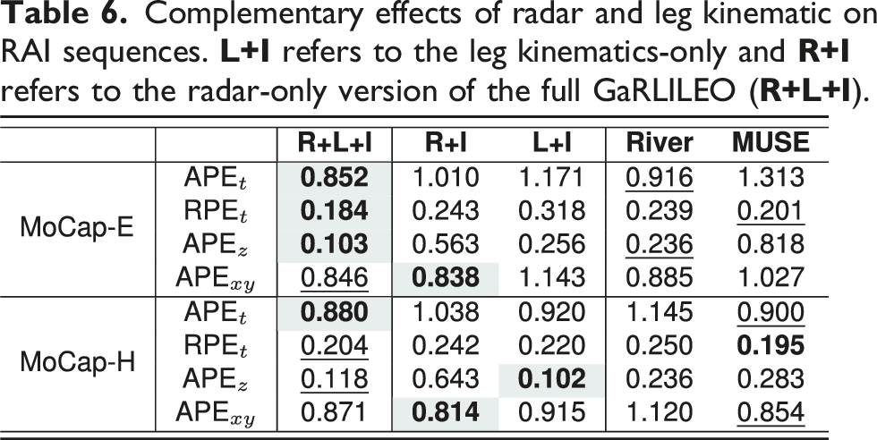
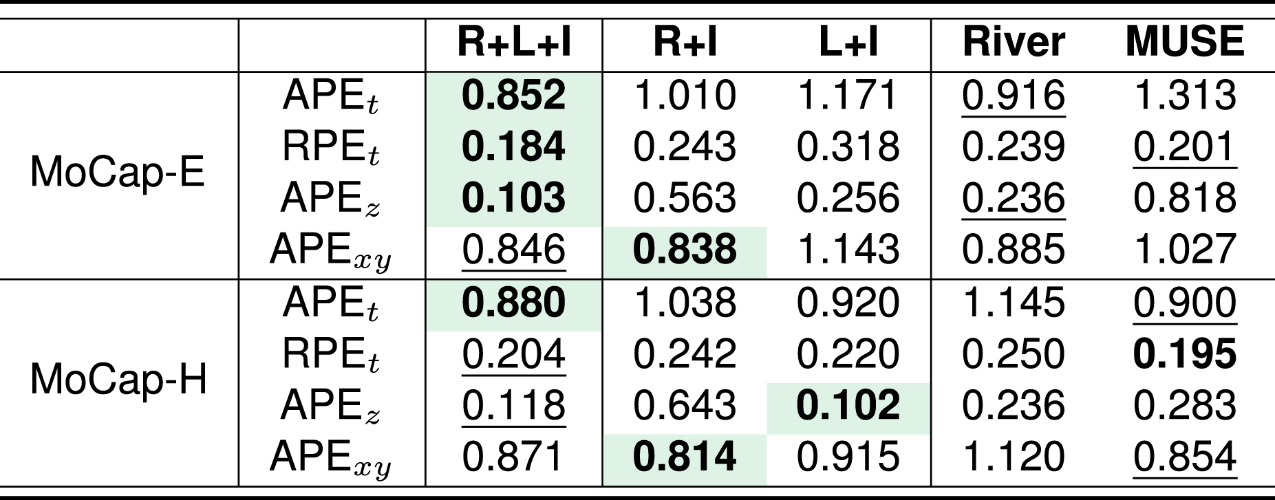
On
7.4. Effect of gravity factors on state estimation accuracy
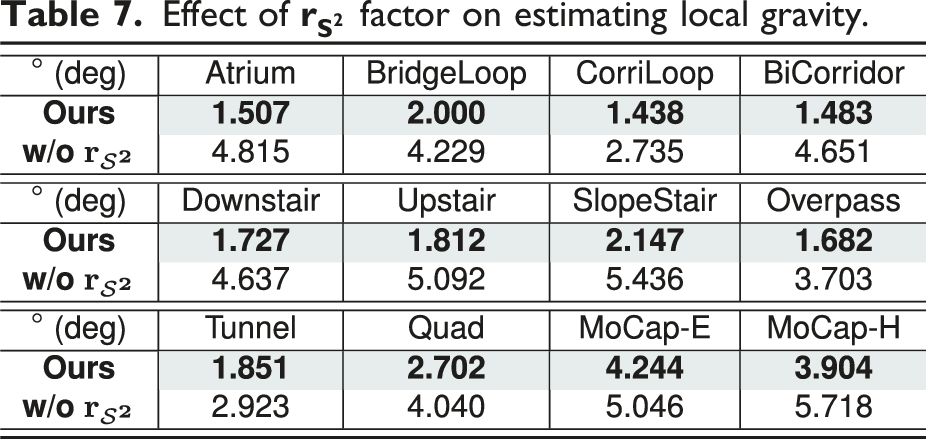
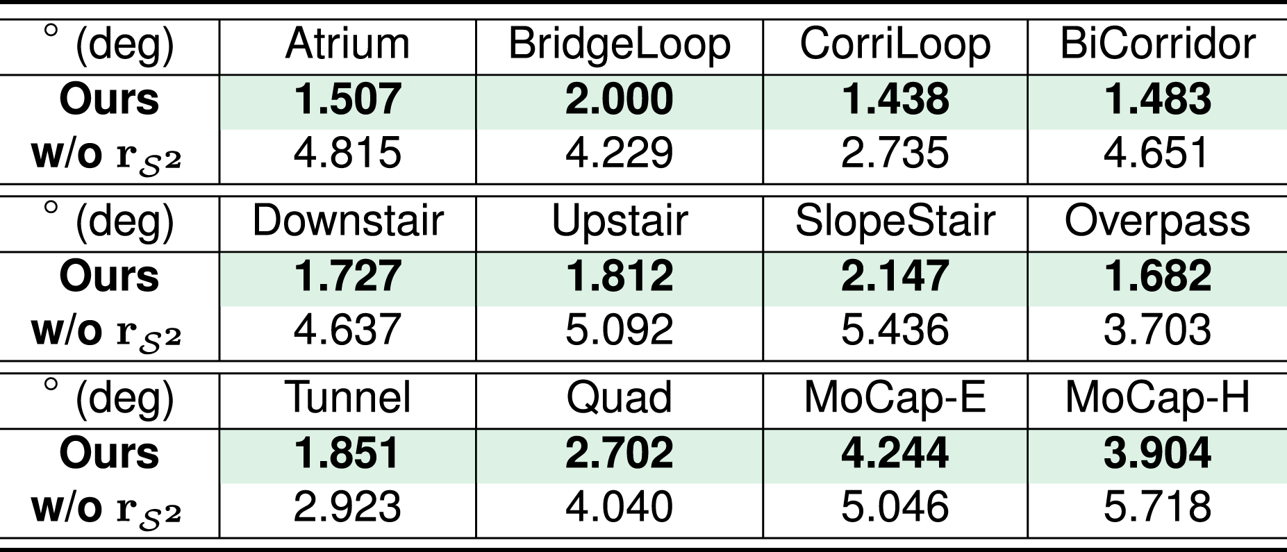
In this subsection, we evaluate the effect of our gravity factors
7.4.1. Effect of the Soft
-Constrained Gravity Factor
In the first sub-experiment, we aimed to highlight the effectiveness of the soft 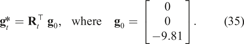
To evaluate roll and pitch observation accuracy, we use the mean angular error of the estimated local gravity vectors over each sequence.
Effect of
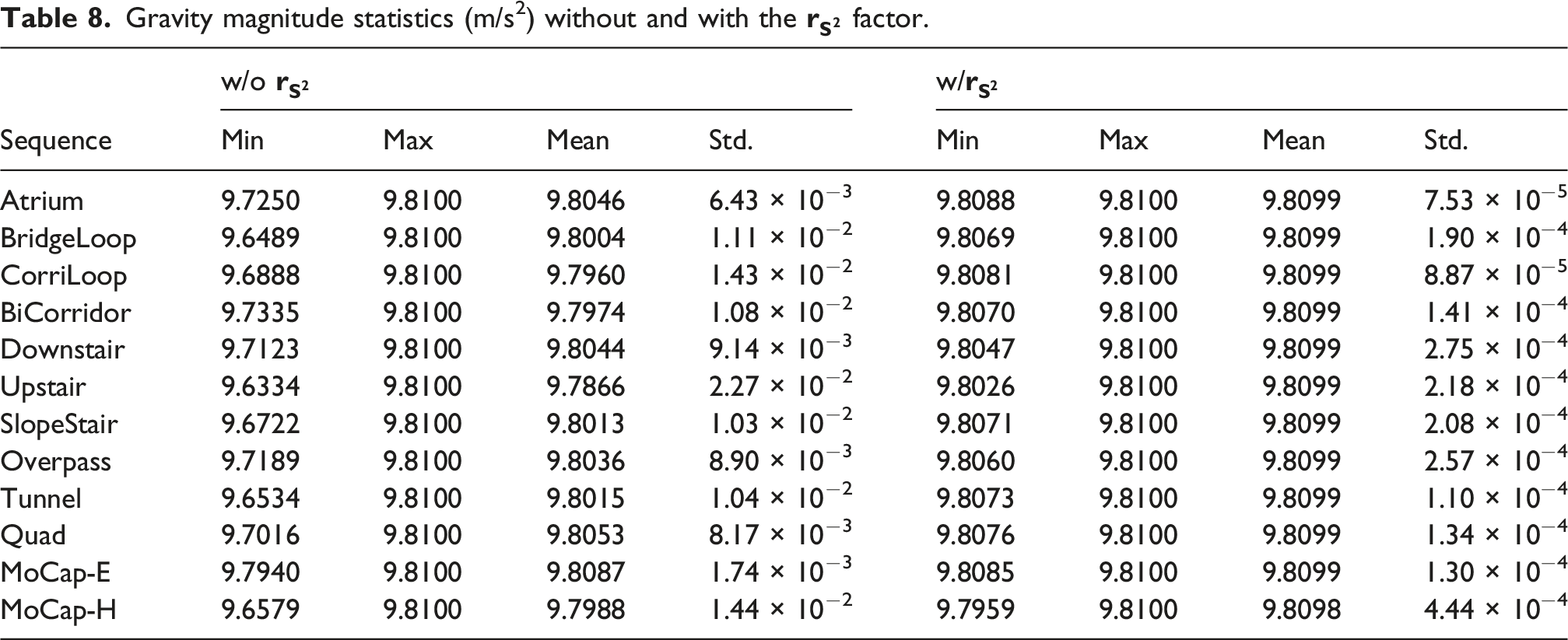
Gravity magnitude statistics (m/s2) without and with the
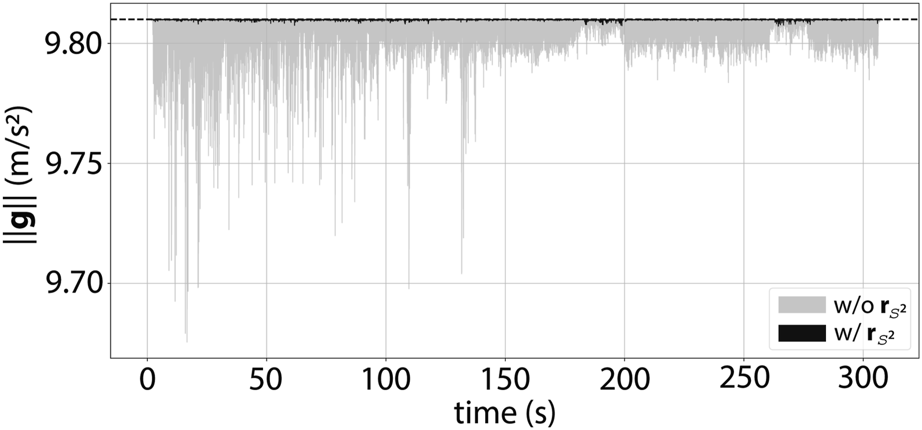
Gravity-norm behavior over time in
As shown in Figure 14, soft
7.4.2. Effect of the Post-Optimization
In the second sub-experiment, we compared the direct vertical drift APE
z
with and without the rotation refinement via post-optimization. As mentioned in the previous sub-experiment, this level of accurate local gravity is directly translated into more precise observability of roll and pitch. As shown in Figure 15, the addition of the Effect of Z-time odometry plot including comparison between with and without the post-optimization. 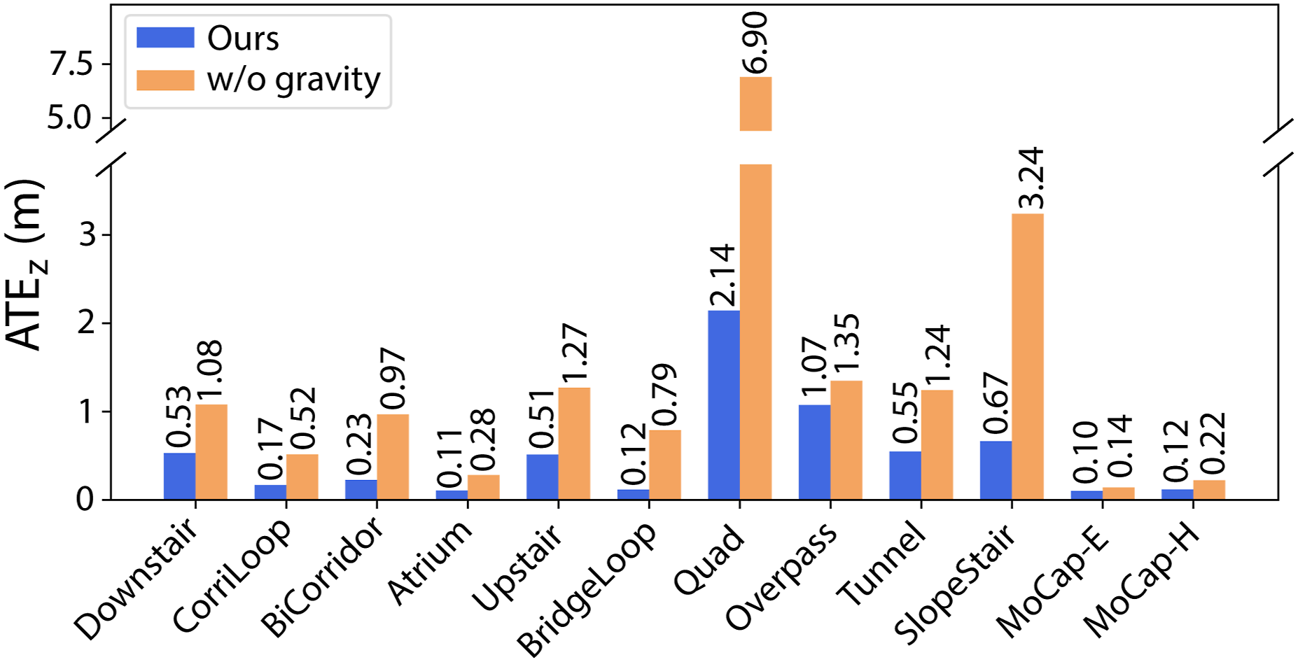
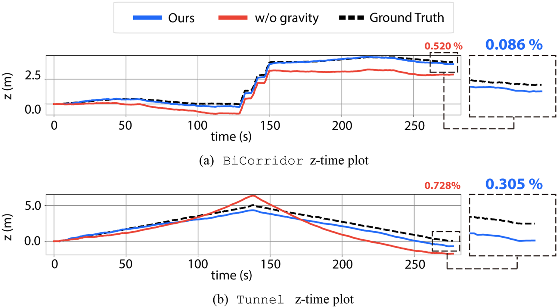
Taken together, these two sub-experiments demonstrate that GaRLILEO maintains a small, single-digit level of accuracy in local gravity estimation, even under aggressive legged robot locomotion, and that this precision is sufficient to deliver robust, low-drift vertical-state estimation on stairs, slopes, and even on slippery, potentially deformable surfaces.
7.5. Effect of velocity bias
Effect of velocity bias on APE t projected onto the xy plane.
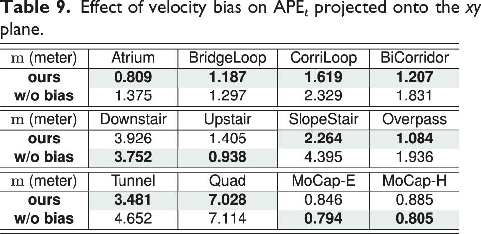
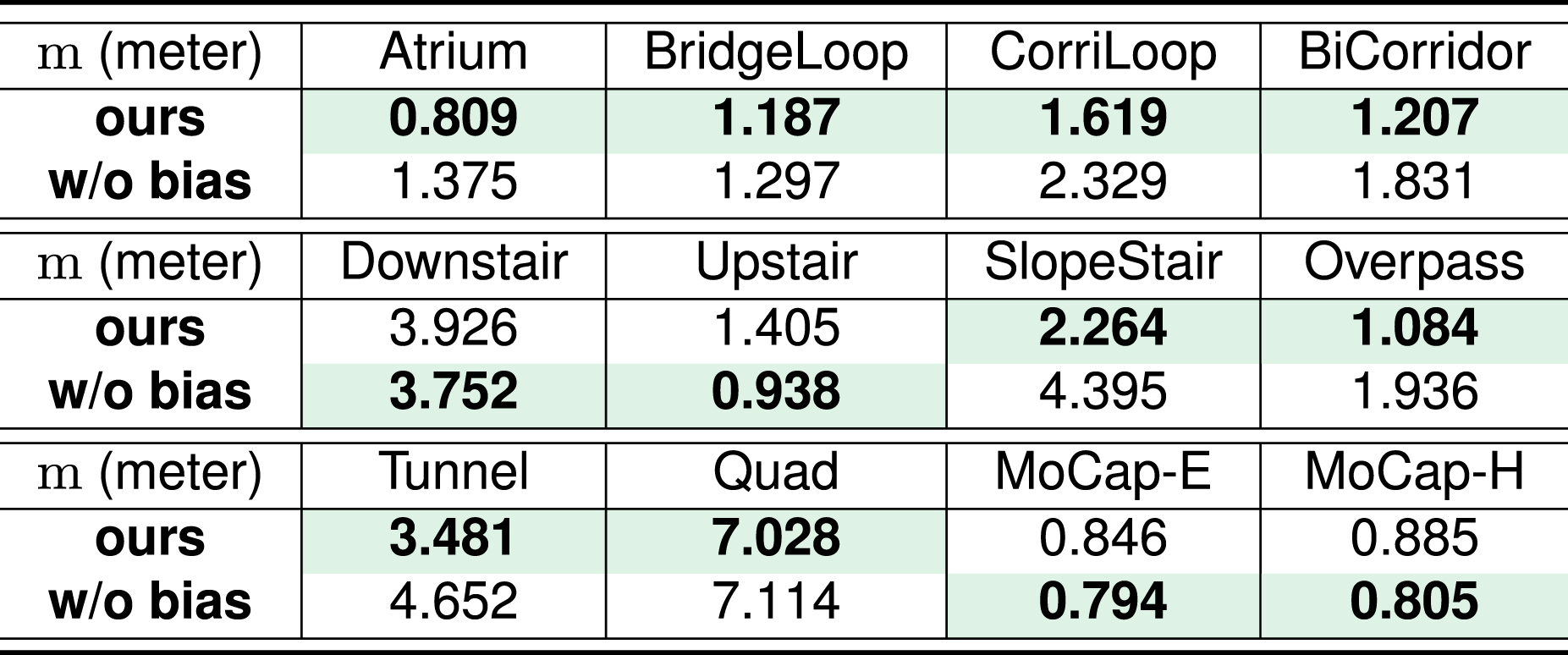
As shown in Table 9, more than half of the sequences exhibit improved accuracy with the bias, while the others perform better without it. Specifically, in the
By contrast, in most indoor sequences, adding the bias improves accuracy, as radar sensors acquire denser, more reliable measurements from nearby static objects. Qualitative odometry is shown in Figure 17, which demonstrates enhanced odometry accuracy for both indoor and outdoor sequences. xy plane plot of odometry estimation with and without velocity bias. On 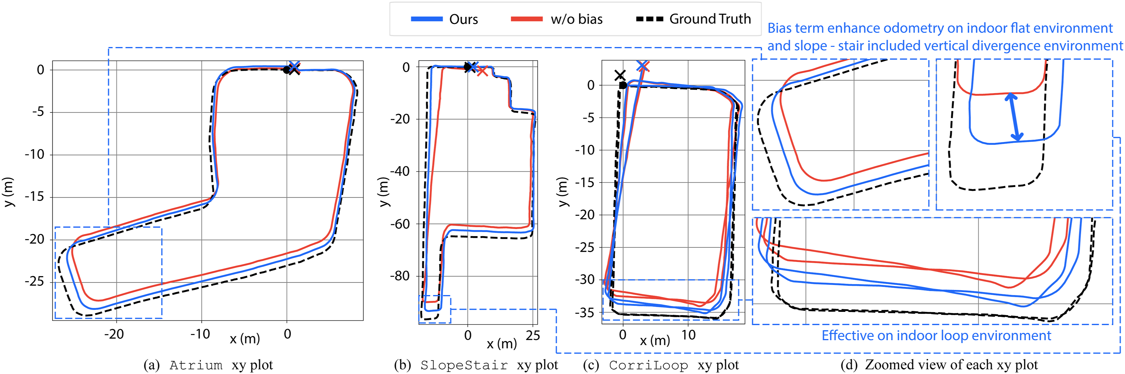
On indoor flat sequences, such as
In
One interesting point about this experiment is that even the
In the two
Overall, the velocity bias can enhance odometry by reducing the discrepancy between radar and leg kinematics when leg kinematics temporally fail due to unanticipated contact issues. Still, a potential limitation of the velocity bias on drastically varying discrepancies remains. This effect is particularly evident in places where the static floor assumption fails, such as
7.6. Real-time capability on edge device
To demonstrate the real-time capability and computational efficiency of our framework, we conducted an experiment by deploying GaRLILEO on an onboard NVIDIA Jetson AGX Orin for the End-to-end edge device test of GaRLILEO on NVIDIA Jetson AGX Orin with 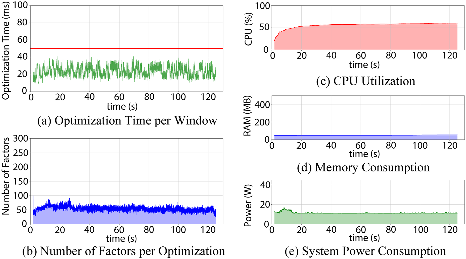
This bounded graph size directly translates to efficient computation frequencies. During the experiment, the end-to-end computation time per sliding window optimization averaged 23.277 ms, with a maximum recorded value of 41.097 ms. Because the incoming radar scans operate at 20 Hz, the system is required to complete its optimization within a 50 ms window. As illustrated by the red threshold line in Figure 18(a), GaRLILEO’s computation time consistently stays below this, guaranteeing real-time deployment capabilities on the edge device without dropping sensor frames.
Furthermore, the overall system throughput and resource consumption demonstrates the stability of GaRLILEO during operation. On the NVIDIA Jetson AGX Orin, GaRLILEO’s CPU utilization averaged 55.856%, while memory consumption remained at an average of 51.013 MB. The average system power usage during execution was 11.521 W, while maximum at 17.198 W. As depicted in Figures 18(c)–(e), the CPU, memory, and power metrics do not exhibit drastic growth over the algorithm runtime. Instead, they maintain a stable and predictable level, confirming GaRLILEO is suitable for deployment on power-constrained systems.
8. Conclusion
In this work, we presented GaRLILEO, a continuous-time radar-leg-IMU odometry framework that leverages B-spline modeling, local gravity estimation, and horizontal velocity bias correction to achieve robust and accurate state estimation in challenging environments. By tightly coupling radar-derived ego-velocity with leg kinematics and inertial measurements, our method addresses the limitations of existing odometry pipelines that suffer from vertical drift, contact slip, and sensor modality degradation.
Extensive experiments across diverse sequences, including long indoor loops, multi-story staircases, outdoor slopes, and environments with severe contact disturbances, demonstrated that GaRLILEO consistently outperforms other SOTA baselines in odometry accuracy. Notably, its continuous local gravity estimation significantly reduces vertical drift. At the same time, the B-spline-based fusion scheme ensures robustness against modality-specific failures such as radar sparsity or leg kinematics slips.
To evaluate the complementary effect of radar and leg kinematics sensors, we tested the performance of the radar-only and leg-only versions of GaRLILEO at
Through two sub-experiments, we validated the effect of proposing local gravity factors on both the accuracy of local gravity estimation itself and odometry in the vertical direction. These experiments demonstrate how GaRLILEO can achieve sub-meter vertical odometry accuracy without relying on loop closure or point cloud registration algorithms, highlighting that reliable local gravity estimation is crucial for robust, vertically low-drift odometry estimation in stairs, slopes, and challenging terrains.
We further analyzed the effect of the velocity bias term and verified that it provides clear benefits in structured indoor environments, while in sparse or highly dynamic outdoor scenes, it may lead to potential performance degradation. This suggests that environment-aware adaptation or improved radar hardware configurations could further enhance robustness.
Overall, our results highlight the potential of continuous-time multi-modal fusion to enable legged robots to navigate reliably in complex real-world environments.
8.1. Limitations and future extensions
Though GaRLILEO demonstrates robust odometry estimation across diverse indoor and outdoor environments, several limitations remain. First, our framework prefers denser radar points for stable velocity spline estimation. In open outdoor areas such as the
To mitigate the above limitations, future work will explore adaptive gravity post-optimization, which dynamically enables or disables the term depending on the reliability of the optimized gravity vector. For classification, fusion with exteroceptive sensors, such as cameras and LiDAR, or friction estimation based on recent contact tactile sensors can be exploited. Furthermore, to expand the field of view and improve odometry robustness, a multi-SoC radar system can be leveraged, which may provide additional yaw orientation observations, as mentioned in Yoon et al. (2023), or enable point cloud registration.
Additionally, the current framework relies on static covariances during optimization. To address the unpredictability of legged robot environments, future work will explore adaptive covariance estimation that dynamically adjusts factor weights based on real-world environmental context and sensor degradation, thereby further enhancing robustness.
Supplemental material
Footnotes
Funding
The authors disclosed receipt of the following financial support for the research, authorship, and/or publication of this article: This work was supported by the Technology Innovation Program (1415187329, 20024355, Development of autonomous driving connectivity technology based on sensor-infrastructure cooperation) funded by the Ministry of Trade, Industry & Energy (MOTIE, Korea), and in part by the Robotics and AI (RAI) Institute.
Declaration of conflicting interests
The authors declared no potential conflicts of interest with respect to the research, authorship, and/or publication of this article.
Supplemental material
Supplemental material for this article is available online.
Note
References
Supplementary Material
Please find the following supplemental material available below.
For Open Access articles published under a Creative Commons License, all supplemental material carries the same license as the article it is associated with.
For non-Open Access articles published, all supplemental material carries a non-exclusive license, and permission requests for re-use of supplemental material or any part of supplemental material shall be sent directly to the copyright owner as specified in the copyright notice associated with the article.