
Abstract
The coking behaviour and NOx emission characteristics of the coke oven are of great significance for coke production. Based on the realisation k-epsilon turbulence model, the P-1 radiation model, the species transport model with eddy dissipation, and the thermal NOx model. A comprehensive model for traditional regenerative coke oven was established with reversing mode and external flue gas recirculation model considering temperature-dependent thermophysical properties. The convective term of model equations was the discretised using the second-order upwind scheme, while the others were applied by the central difference scheme. The coking behaviour of the coke oven with external flue gas recirculation was numerically solved through the SIMPLE algorithm, and the effects of reversing period and external flue gas recirculation ratio on the coking behaviour were explored. When increasing the reversing period, the mean temperature of the vertical flue increases, and the coking time decreases, but the temperature uniformity of the carbonisation chamber becomes worse. As the external flue gas recirculation ratio increases, the average temperature of the vertical flue decreases, and the NOx concentration at the outlet decreases, yet the coking time increases. These results would provide useful information for guiding the improvement of coke oven operation and reducing NOx emissions.
Keywords
Introduction
Recently, strict environmental policies and the latest emission standards require the steel industry to lower energy consumption, improve coke quality and reduce NOx emissions. However, the coke oven is an important unit of coking production all around the world. Many substantial technologies of coke oven have achieved great success over the past two decades, but traditional regenerative coke oven with large productivity would continue to exist near the future. So far the operation of the coke oven, coking production are very complex procedure, including turbulent flow and thermal radiation in the vertical flue, the heat conduction of the partition wall, the endothermal reaction and the heat conduction of the coking coal in the carbonisation chamber, the convective heat transfer in the regenerative chamber. Moreover, the chamber temperature in the vertical flue is very high, and the temperature difference in the regenerative chamber is also relatively large. Due to the airtightness, safety, and stability of the coke oven, the combustion characteristics of the early coke oven were only predicted by the measurement temperature of the nose bridge brick. The operators cannot grasp the combustion status inside the coke oven and lack understanding of the working conditions about the coke oven.
Currently, since the experiment of the coke oven is expensive and difficult, the numerical simulation may more conveniently reveal the thermal mechanism behind the coking behaviour of the coke oven. Consequently, the mathematical modeling of the coke oven has been paid attention. By numerical simulation of the heating system of the coke oven, it is possible to demonstrate the transport phenomena of the heating system, uncover the impact of operation parameters on the coking behaviour, and thus attain the optimal working conditions. With the advances of numerical technology about the coke oven, the numerical formulation of the coke oven is also constantly developing. From a one-dimensional model of the combustion chamber or carbonisation chamber to a three-dimensional model, from a heat transfer model of the carbonisation chamber with constant properties to variable properties, and then to a coupled model involving the carbonisation chamber and combustion chamber, from a single chamber to a multi-chamber, and then considering periodic heat transfer in carbonisation chamber, heat transfer in the regenerative chamber, as well as pyrolysis of the coking coal, volatile matter devolatilisation, flow and heat transfer of raw gas in carbonisation chamber, which is increasingly closer to the real coking production. The literature review of coke oven modeling is listed in Table 1.
Literature review of coke oven modeling.
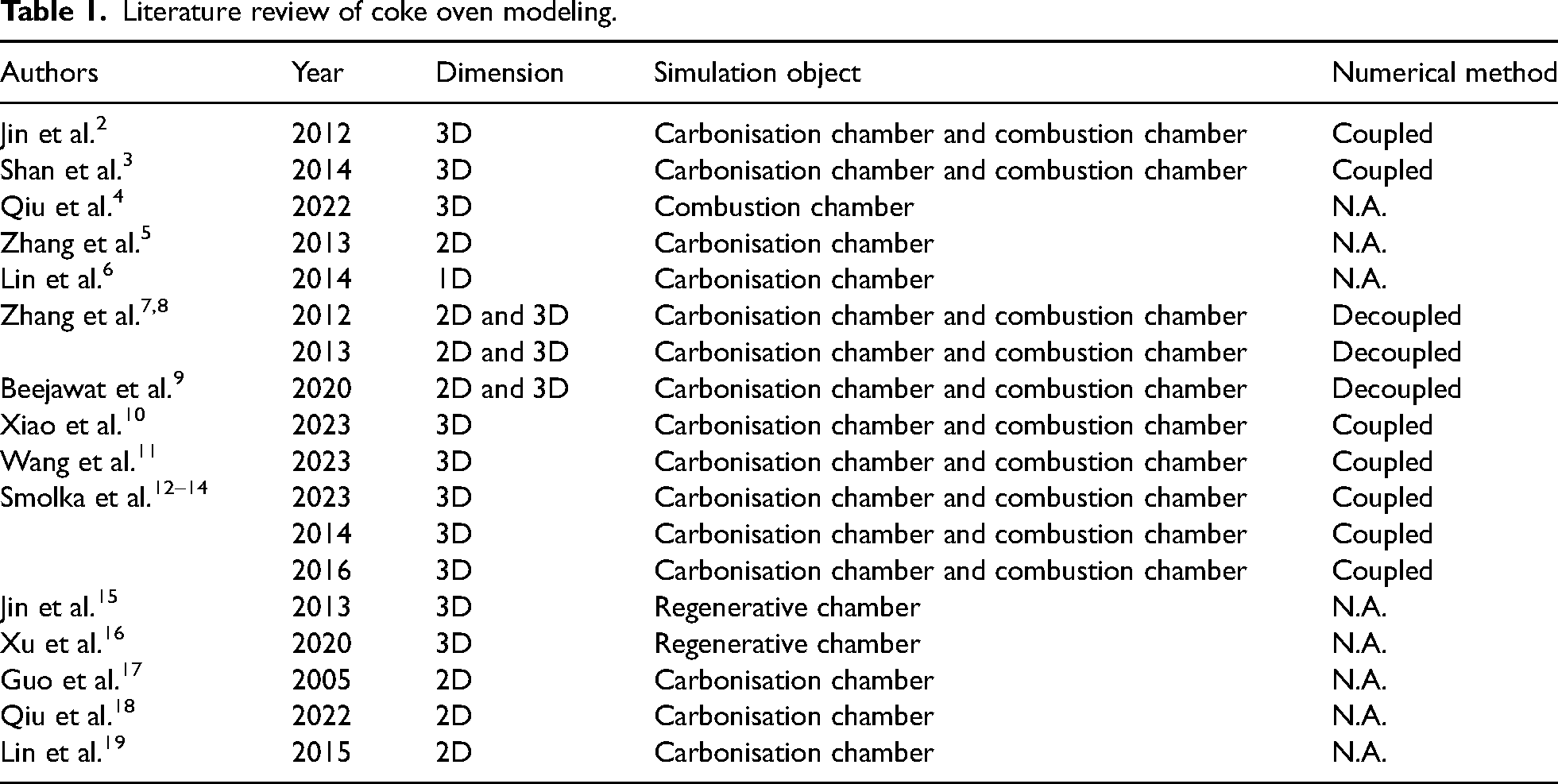
Many efforts have been made to perform numerical investigations of the coke oven in open literature. Merrick et al. 1 proposed a series of pyrolysis model, including moisture evaporation, volatile matter devolatilisation, gas flow and heat transfer of the coking coal in the carbonisation chamber, which laid on theoretical foundation for the numerical solution of the coke oven. Jin et al. 2 described a two-way coupled model between the carbonisation chamber and the combustion chamber, treating heat transfer of the carbonisation chamber as the non-steady process, while the periodic combustion in the vertical flue was thought as the steady state. Shan et al. 3 formulated a three-dimensional chamber model of the coke oven and discussed the influence of moisture content and initial coal temperature on the temperature distribution of the carbonisation chamber. Qiu et al. 4 put forward mixed combustion mode of pulverised coal and gaseous fuel, and numerically studied the influence of air–fuel ratio and coal injection position on the temperature characteristics of the combustion chamber of the coke oven. Zhang et al. 5 presented a thermal process model for the carbonisation chamber of the coke oven and explored the effects of moisture content and coking coal temperature on the coking time. Lin et al. 6 developed a mathematical model with consideration of the shrinkage of the coking coal. The effects of moisture, the chamber temperature on the shrinkage of the coking coal were analysed. Zhang et al.7,8 and Beejawat et al. 9 combined the multi-dimensional model of the combustion chamber with the one-dimensional model of the carbonisation chamber and proposed two decoupling solution ideas to solve the coking problems, thereby improving computational convergence and efficiency. Xiao et al. 10 built the multi-chamber model for the coke oven and analysed the thermal effect of high thermal conductivity silica bricks on the heat transfer of the coke oven. Wang et al. 11 simultaneously considered varied fuel rate, water evaporation and condensation, volatiles release and blend porosity variation in modeling fully coupled heating and coking model. By changing the heat flux distribution on the brick walls, Lukasz Slupik research group12–14 introduced a periodic and non-steady two-dimensional numerical model for the carbonisation chamber of the coke oven. Jin et al. 15 modeled a three-dimensional mathematical model of the regenerative chamber of the coke oven including the small flue and ramp zone, revealing the gas flow laws in the regenerative chamber. Xu et al. 16 constructed a three-dimensional heat transfer model for the regenerative chamber of the coke oven to simulate the unsteady periodic heat transfer of the regenerative chamber. To further describe the coking process of the coke oven, Guo et al., 17 Lin et al., 18 and Qiu et al. 19 established a two-dimensional model for the flow and heat transfer of the volatile matter in the carbonisation chamber, simulating the gas–solid two-phase heat transfer between volatile matter and coal particles during the coking process of the coking coal.
In addition, numerical technology could be also used to predict NOx emission and develop strategies for reducing NOx emissions. These flue gas NOx reduction technologies mainly cover NOx control technologies for post-combustion, such as selective non-catalytic reduction (SNCR) and selective catalytic reduction (SCR) in the vertical flue or regenerative chamber, as well as combustion denitrification technologies, including air staged combustion, oxygen-enriched combustion and flue gas recirculation. The literature review of NOx reduction strategies for coke oven is listed in Table 2.
Literature review of NOx reduction strategies for coke oven.
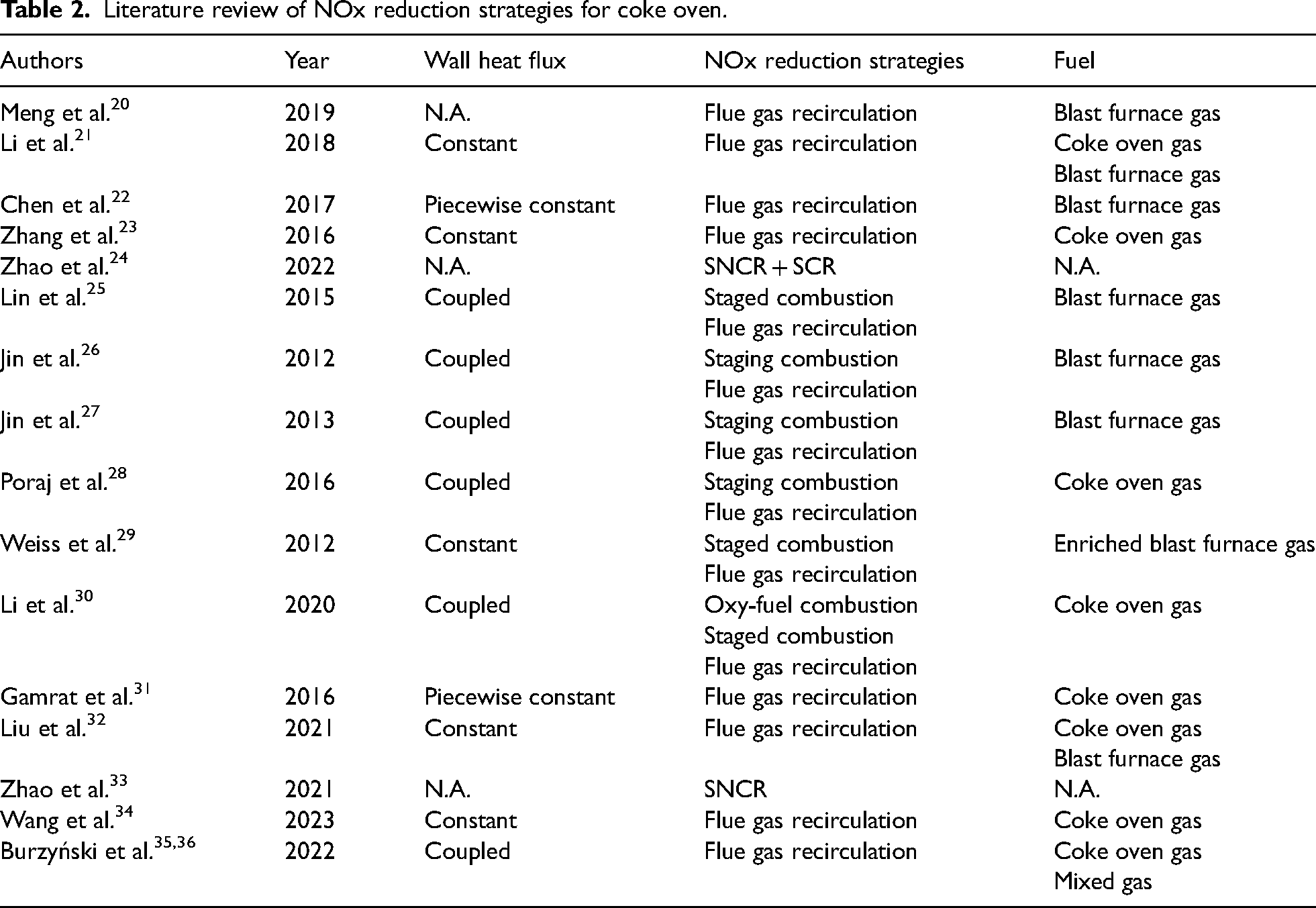
As a result, the problems of NOx emissions from the coke oven have been studied by numerous authors. Meng et al., 20 Li et al., 21 Chen et al. 22 and Zhang et al. 23 examined the effects of air-preheated temperature, excess air coefficient and heat flux on NOx emission from the vertical flue of the coke oven. Zhao et al. 24 simulated the NOx concentration distribution characteristics of SNCR and SCR reaction regions. Lin et al. 25 found that when the coke oven adopts staged combustion, the temperature distribution of the vertical flue gets more uniform. Jin et al.26,27 also pointed out that large capacity coke oven with staged combustion could improve the heating uniformity of chamber temperature while reducing the NOx concentration in flue gas. When blast furnace gas is mixed with natural gas or converter gas, Proaj et al. 28 and Weiss et al. 29 ascertained that as the secondary air mass flow rate increases, NOx emissions decrease. Li et al. 30 adopted low NOx emission technology which combines oxygen fuel combustion and staged combustion, achieving a reduction in NOx emissions from 1155 mg/m3 to 87 mg/m3. Gamrat et al. 31 believed that external flue gas recirculation technology can reduce the formation of NOx during the combustion process of the vertical flue of the coke oven, and achieve 50% NOx reduction efficiency when the external flue gas recirculation ratio reaches 20%. Liu et al. 32 explored the effects of flue gas recirculation ratio, preheated temperature, and coke oven gas ratio on NOx generation characteristics. The average NOx content in flue gas at the outlet goes down from 364 mg/m3 to 228 mg/m3. Based on the cascade utilisation of waste heat and SNCR technology Zhao et al. 33 proposed a new-type coke oven regenerator with ammonia injection space. The essence of NOx reduction strategies was to ensure the residence time for mixing, enlarge the practical contact opportunities of NH3 and NO as much as possible, enhance the competitive advantage of NO reduction to NO production and realise the best SNCR process at a suitable temperature. Wang et al. 34 have attempted to modulate the structure of the fuel inlet to dilute the fuel content for a further mitigation of NOx emission, and detailed insights into the flue gas flow and temperature distribution. Burzyński et al.35,36 optimised heating flue structure and operating characteristics of the coke oven to provide a substantial reduction of NOx emissions.
Unfortunately, most authors overlook the periodic switch of the inlet and outlet boundaries during the combustion process of the coke oven. Simply changing the coke-side or gas-side temperature profile represented the reversal firing between the vertical flues, without considering the change in thermal properties from coking coal to coke. The coking behaviour and NOx emission characteristics of the coke oven with external flue gas recirculation are few reported, which need still more advanced studies to demonstrate the coking production.
To capture and reproduce the coking behaviour of coke oven with external flue gas recirculation, a new numerical simulation method based on FLUENT UDF and FLUENT Scheme was used to develop the comprehensive model to reveal the coking behaviour of the coke oven with external flue gas recirculation, including reversing combustion mode, effective thermophysical formula, external flue gas recirculation model and result save rule of the coking data. The effect of the reversing period and the external flue gas recirculation ratio on the coking behaviour of the coke oven with external flue gas recirculation was innovatively examined. The obtained results would help to reveal the coking behaviour of the coke oven with external flue gas recirculation, which provides a powerful guidance for the operators to improve the operational efficiency of the coke oven and develop NOx emission reduction strategies.
Physical model and solution conditions
Taking JN43-58 coke oven as an example, the single combustion chamber consists of a pair of adjacent vertical flue. The hot gas was successively gone through ascending flue, crossing hole, descending flue and recirculation hole. Combined with working characteristics and structural periodicity, the geometry model was selected as the adjacent vertical flue, left and right partition wall, and two half carbonisation chambers, as indicated in Figure 1. The fuel and air inlet duct, as well as the flue gas outlet duct, were located below the vertical flues. Without affecting numerical results, to better study the coking mechanism behind the heating system, the following simplifications were made:
Transforming the physical and chemical change during the coking process into physical properties change. The coking coal entering the coke oven does not contain moisture, and the evaporation was ignored. Without considering the shrinkage, flow and heat transfer of gas products in the carbonisation chamber, it is assumed that the coking coal has been filled into the carbonisation chamber. The temperature gradient in the normal direction on the central plane of the coking coal on both sides is very small, and it is assumed to be approximately symmetrical. The contact walls with the surrounding environment were considered as the adiabatic walls. All carbonisation chambers were assumed as solid coking coal to simulate the conversion of coal to coke. The interval time of reversing combustion between the vertical flues was neglected.
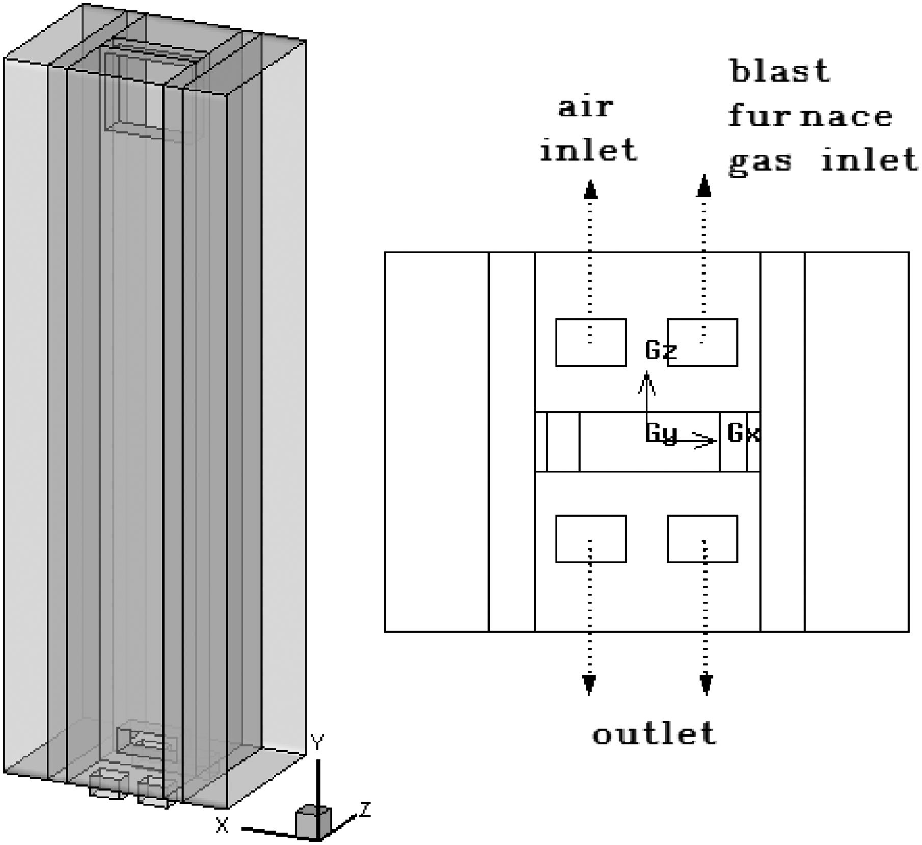
Calculation domain of coke oven.
During the operation of the coke oven, the gas inlet and the flue gas outlet were exchanged periodically, and a part of the discharged flue gas was recycled, as depicted in Figure 2. Assuming that the mass flow rate at the mixing inlet is fixed, the air mass flow rate gradually decreases, and the flue gas mass flow rate continuously increases. One of the two outlets is closed and set to be the adiabatic wall, so that the flue gas always exits from another outlet. Besides, for external flue gas recirculation, it is necessary to recalculate the mass flow rate, mass fraction and temperature at the air inlet, that is, update the mass fraction of each species and temperature at the mixing inlet. The specific method is taken from the published literature. 31
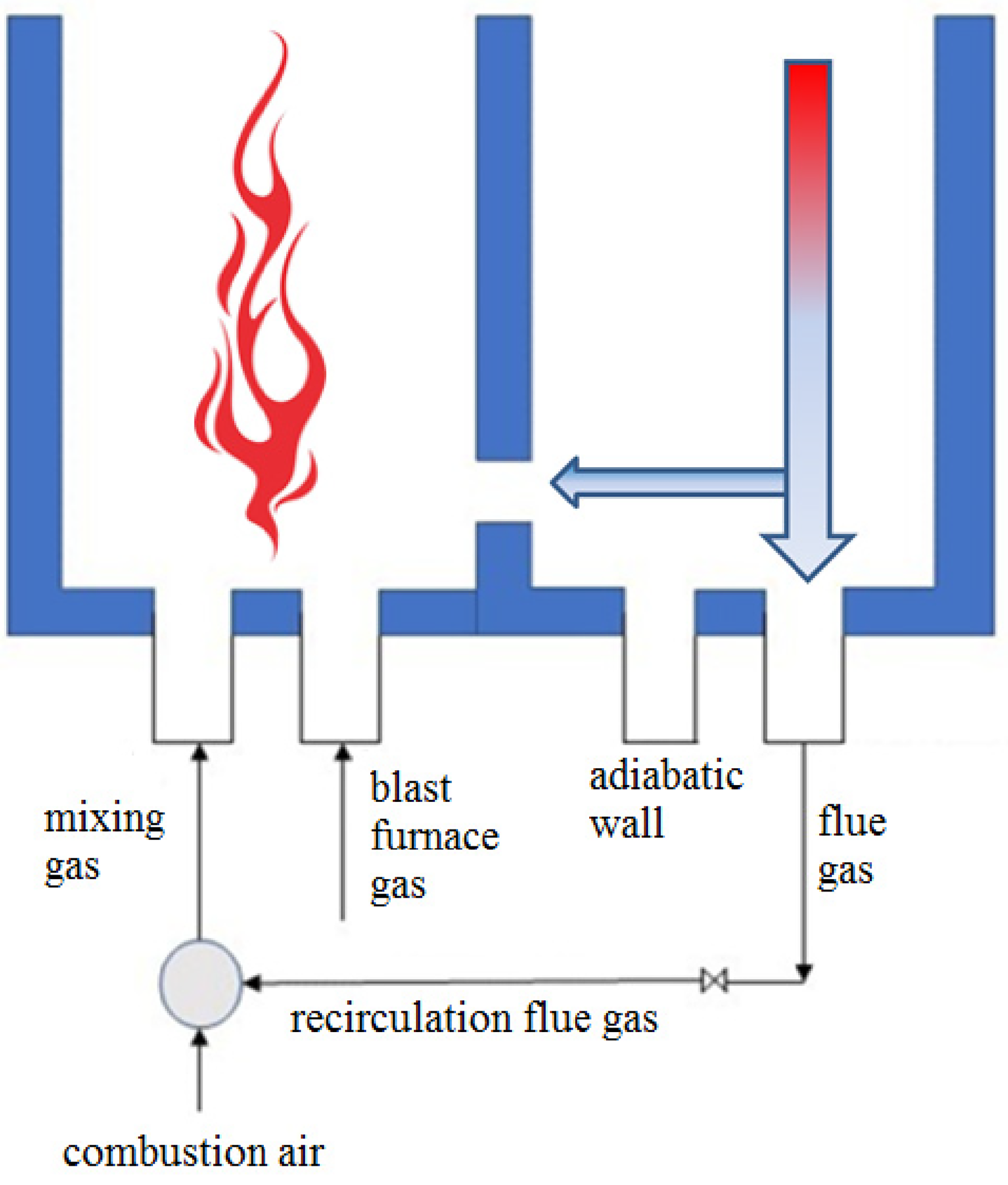
Schematic diagram of external flue gas recirculation for coke oven.
The ordinary silica bricks were used for the walls between the carbonisation chamber and the combustion chamber. The composition of blast furnace gas, chemical reaction mechanism and physical properties of these materials could be estimated in the previous work. 10 Among them, the coking coal type in this article was specified as gas coal, and the effective physical properties, such as bulk density, specific heat and thermal conductivity, are demonstrated in Figure 3. 37
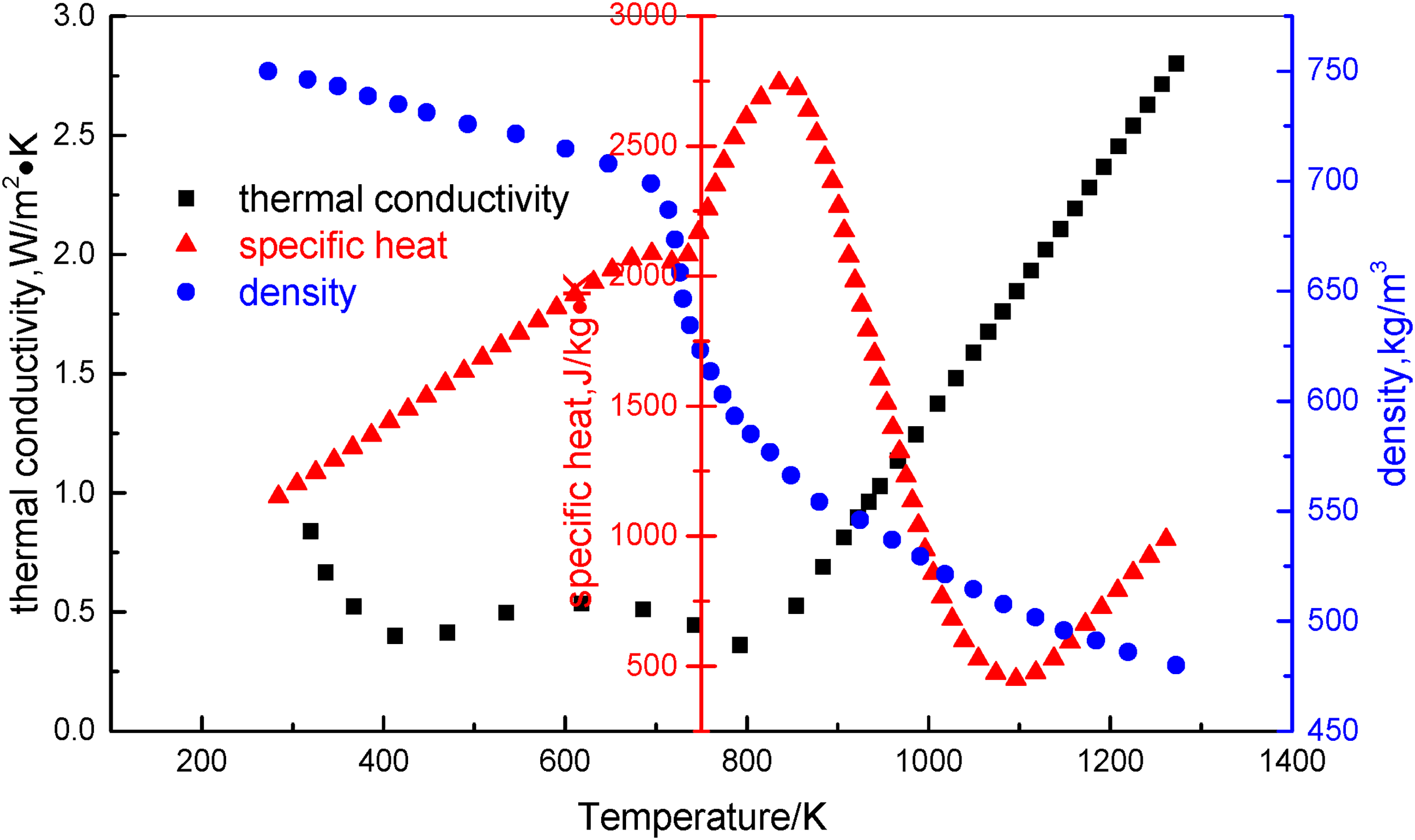
Physical parameters during coking process of gas coal.
Both blast furnace gas and combustion air are defined as mass inlet boundaries, with mass flow rates of 0.00273 kg/s and 0.0195 kg/s for the typical case, respectively. And these gases are preheated to 1373 K. The gas outlet is prescribed to be free flow boundary, the left and right central planes of the carbonisation chamber are supplied as symmetry boundaries, and the rest walls are regarded as adiabatic boundaries. The initial temperature and bulk density of the coking coal, as well as the initial temperature of the partition wall are successively 300 K, 750 kg/m3 and 1400 K.
Implementation of customised models
The coking phenomena of the coke oven with external flue gas recirculation are very complex, mainly including periodic combustion of the gas phase in the vertical flue, coal pyrolysis, melting and solidification in the carbonisation chamber, heat conduction inside the partition wall, and mixing of partial flue gas and combustion air. There are several mathematical models to consider when running this simulation in the FLUENT software. The heat transfer equation for the partition wall and the coking coal in the carbonisation chamber is simplified into a pure heat conduction equation. For the combustion chamber, due to the high-speed injection of combustion air and blast furnace gas at the inlet, the flow mode is jet flow. The high-temperature airflow sequentially flows from the ascending vertical flue, passes via the crossing hole and then exits through the descending vertical flue. Due to the recirculation hole of the exhaust gas, some descending exhaust gas passes through the recirculation hole and enters the ascending vertical flue again, resulting in turbulent flow throughout the entire process. Therefore, the realisable k-epsilon turbulence model with the enhanced wall treatment for jet turbulent flow was selected. The mixing of separate gas phase in the vertical flue results in intensely turbulent non-premixed combustion. The species transport model was adopted to model the gas phase combustion, and the eddy dissipation model was used to represent the interaction effects between gas combustion and turbulence flow. The gas flow in the heating flue is relatively slow, with radiation heat transfer accounting for 90% to 95%, and convective heat transfer only accounting for 5% to 10%. The heat released from gaseous combustion is mainly transferred through thermal radiation via the partition wall to heat up the coking coal in the carbonisation chamber. Convective heat transfer contributes little to coking. Consequently, radiation heat transfer in the vertical flue is crucial, and the impact of radiation heat transfer on turbulent combustion needs to be considered. Owing to the large optical thickness of the vertical flue, the P-1 radiation model was used to describe the radiation heat transfer inside the vertical flue, and the absorption coefficient was solved using the gray gas-weighted model. The NOx generated during the combustion process of the coke oven is mainly thermal NOx, and the Zeldovich mechanism was employed to describe the thermal NOx model. The NOx generation rate was determined using a post-processing method based on temperature and mass fraction of flue gas. Overall, the basic models include general governing equations, that is, continuity equation, energy equation, momentum equation, and species equation, realisable k-epsilon turbulence model, P-1 radiation model, eddy dissipation model and thermal NOx model. Additional details of these basic models were introduced in the open documents.30,31
The above models were numerically solved by the FLUENT package. In the Cartesian coordinate system, the computational domain was divided into finite control volume using the structured non-uniform grid. The second-order upwind scheme was utilised for discretising the convection for these equations, while the others were applied by the central difference scheme. The SIMPLE algorithm was used to deal with pressure–velocity coupling, and the numerical calculation was stopped until all governing equation residuals were less than the default convergence criteria. The existing models and user-defined models exchange information such as the temperature, composition, and mass fraction of flue gas at the outlet, reversing period, and effective physical properties during the coking process of the coke oven. They work together to accomplish the numerical simulation of the coking process of the coke oven with external flue gas recirculation, as exhibited in Figure 4. The effective thermophysical formula for the coking coal in the carbonisation chamber is defined as:


Calculation flow chart of customised model during coking process of coke oven under external flue gas recirculation.
Where, λ is thermal conductivity, cp is specific heat and ρ is bulk density.
The combustion reversing mode is represented as:
The saving mechanism for the coking data is written as:
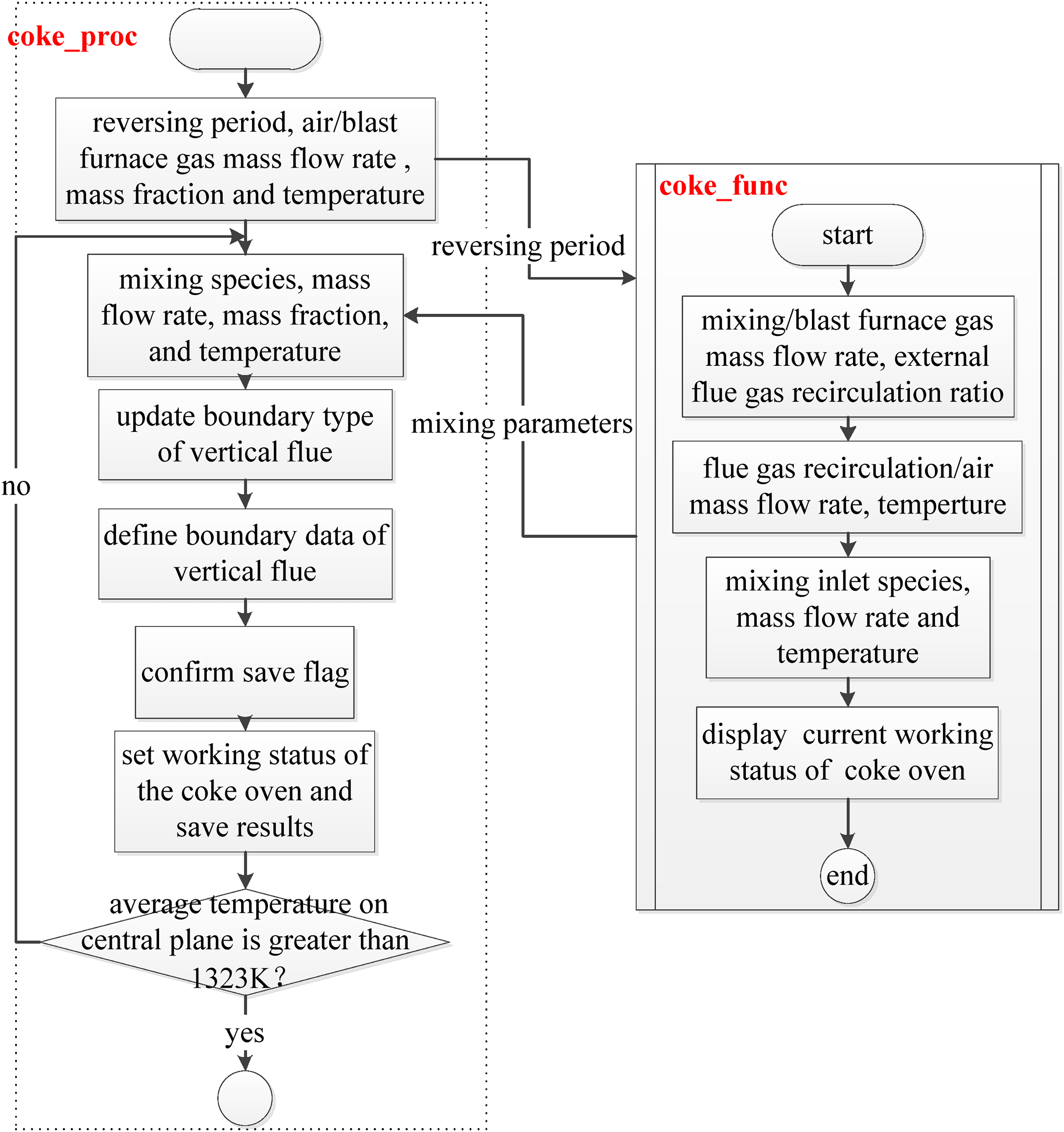
The basic models provide the species, mass fraction, and temperature of flue gas at the outlet. The external flue gas recirculation model obtains these flue gas parameters, calculates the mass fraction and temperature of combustion air at the inlet, and uses these parameters to update the air inlet boundary values. According to the time step size of the basic models, the reversing mode determines the iteration number based on the reversing period and completes this iteration calculation. The basic models periodically exchange the inlet and outlet boundaries based on the reversing mode and determine the boundary data based on the external flue gas recirculation model. According to the effective thermophysical properties formula of the coking coal in the carbonisation chamber, the basic models obtain the coking temperature on the central plane of the carbonisation chamber. When the coking temperature reaches approximately 1323 K, the coking task was completed, and the simulation stop signal was sent to FLUENT software. The coking saving rule stores numerical results according to coking temperature at different coking phases. Simultaneously, it also includes the gas temperature in the vertical flue, mass fraction of each species at the outlet, coking temperature, and heat flux on the central plane of the carbonisation chamber. The FLUENT simulation solution for the coking process of the coke oven under external flue gas recirculation is plotted in Figure 5, and the user-defined functions are explained as follows:
The function init_func initialises the solution settings for the coking process of the coke oven with external flue gas recirculation, including the initial temperature and initial bulk density of the coking coal at the ambient conditions, and initial temperature of the partition wall. The properties function such as coal_density, coal_thermal_conductivity and coal_specific_heat determine the effective physical properties of the coking coal, namely bulk density, thermal conductivity and specific heat. The process coking_proc and the function coking_func exchange information such as the composition, temperature and mass fraction of flue gas at the outlet, and reversing period, and store the simulation results based on the coking stages at different coking times. According to the reversing mode, redefine the inlet and outlet boundaries, and then based on the external flue gas recirculation model, determine species, mass fraction, and temperature of flue gas at the outlet, as well as the mixed inlet mass flow rate, air mass flow rate and external flue gas recirculation mass flow rate. Determine the composition, mass fraction and temperature of the mixed gas inlet, and then obtain the numerical boundary values. Meanwhile, obtain the effective physical properties of the coking coal by the piecewise fitted formula, and sequentially save the corresponding results when the coking temperature reaches 403 K of the moisture evaporation stage, the volatile matter devolatilisation stage of 728 K, the semi-coking stage of 1048 K, and the coking end stage of 1323 K at different coking times. When the coking temperature on the central plane of the carbonisation chamber reaches 1323 K, end the coking operation of the coke oven under the external flue gas recirculation to exit FLUENT software.
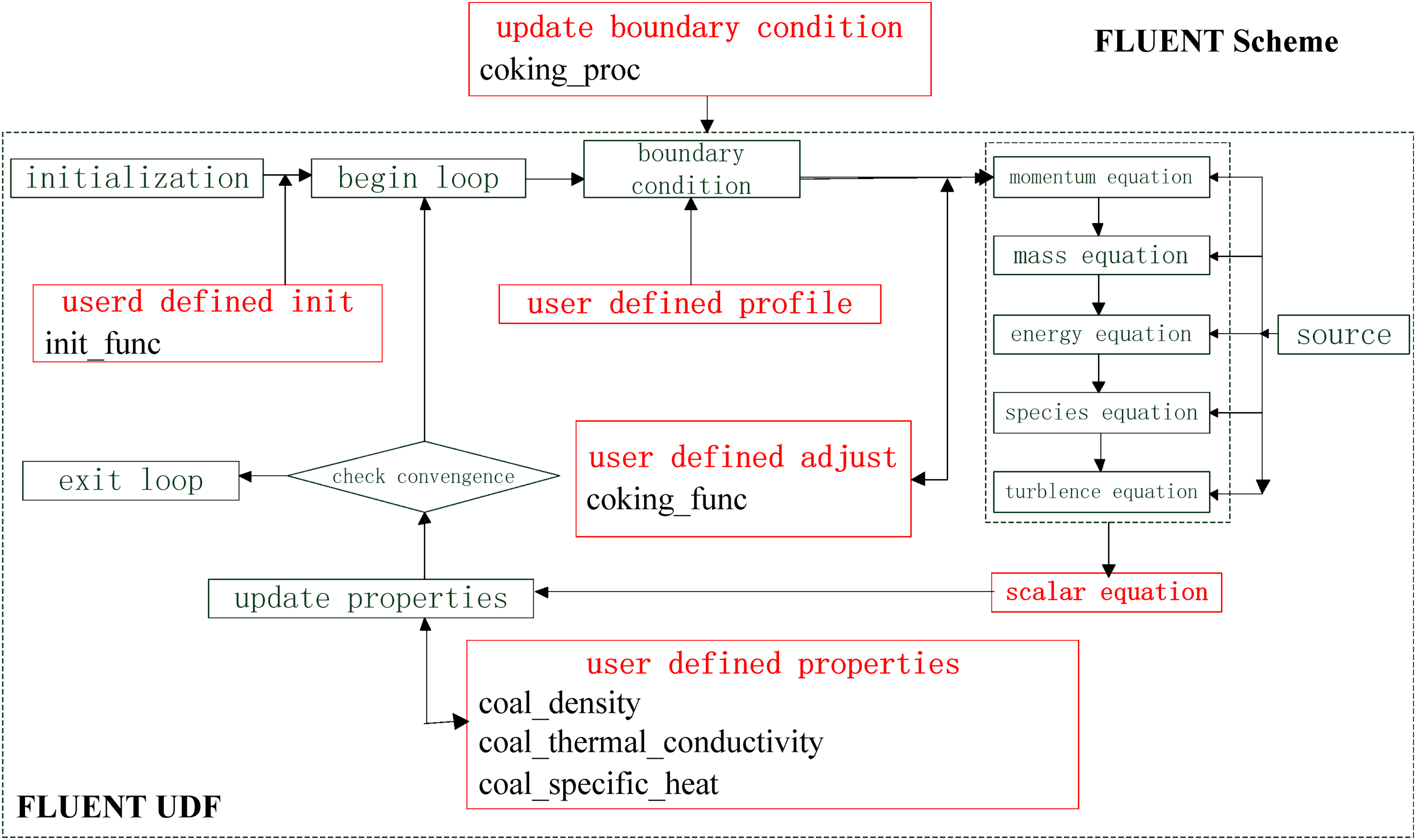
FLUENT solution diagram of coking process of coke oven under external flue gas recirculation.
Model validation and grid sensitivity test
When meshing the geometry model of the coke oven, different grid systems were applied to different regions due to the large difference in scale between the chambers and the silica bricks. Cube grids were used for the combustion chamber, carbonisation chamber, crossing hole, recirculation hole, fuel/air inlet and flue gas outlet on both sides, while tetrahedron grids were used for other domains and local grids were refined to ensure grid quality and improve simulation accuracy. In this study, grid independent check is done with different grid densities. When conducting grid independence test, the combustion chamber and the carbonisation chamber were emphasised. Grid sizes of 50 mm, 40 mm and 30 mm were selected, and the same initial conditions were set for these solution problems, namely, the inlet temperature of combustion air is 1373 K, the inlet temperature of blast furnace gas is 1373 K, the initial temperature of coking coal is 300 K, the reversing period is 25 minutes, and the external flue gas recirculation ratio is 0%. The coking time was used as the evaluation indicator to determine the grid quality, as shown in Figure 6. The grid density for different grid sizes is 212,249 cells, 398,084 cells and 715,608 cells, respectively. With the increase of the grid density, the central temperature of the coking coal in the carbonisation chamber increases faster, and the coking time required for the central temperature of the coking coal to reach the coking temperature of 1323 K is shortened. There is a significant difference between the coarse density and the medium density, while the results calculated by the fine grid are almost the same as those by the medium density, and the corresponding coking time for different grid sizes are 17.91 hours, 17.61 hours and 17.21 hours, respectively. Considering the accuracy, resource and efficiency of the numerical calculation, the selected grid size is 40 mm. Besides, based on the previous literature, 14 the selected time step size is 50 seconds. All the transport equations were solved in each time step with 20 iterations.
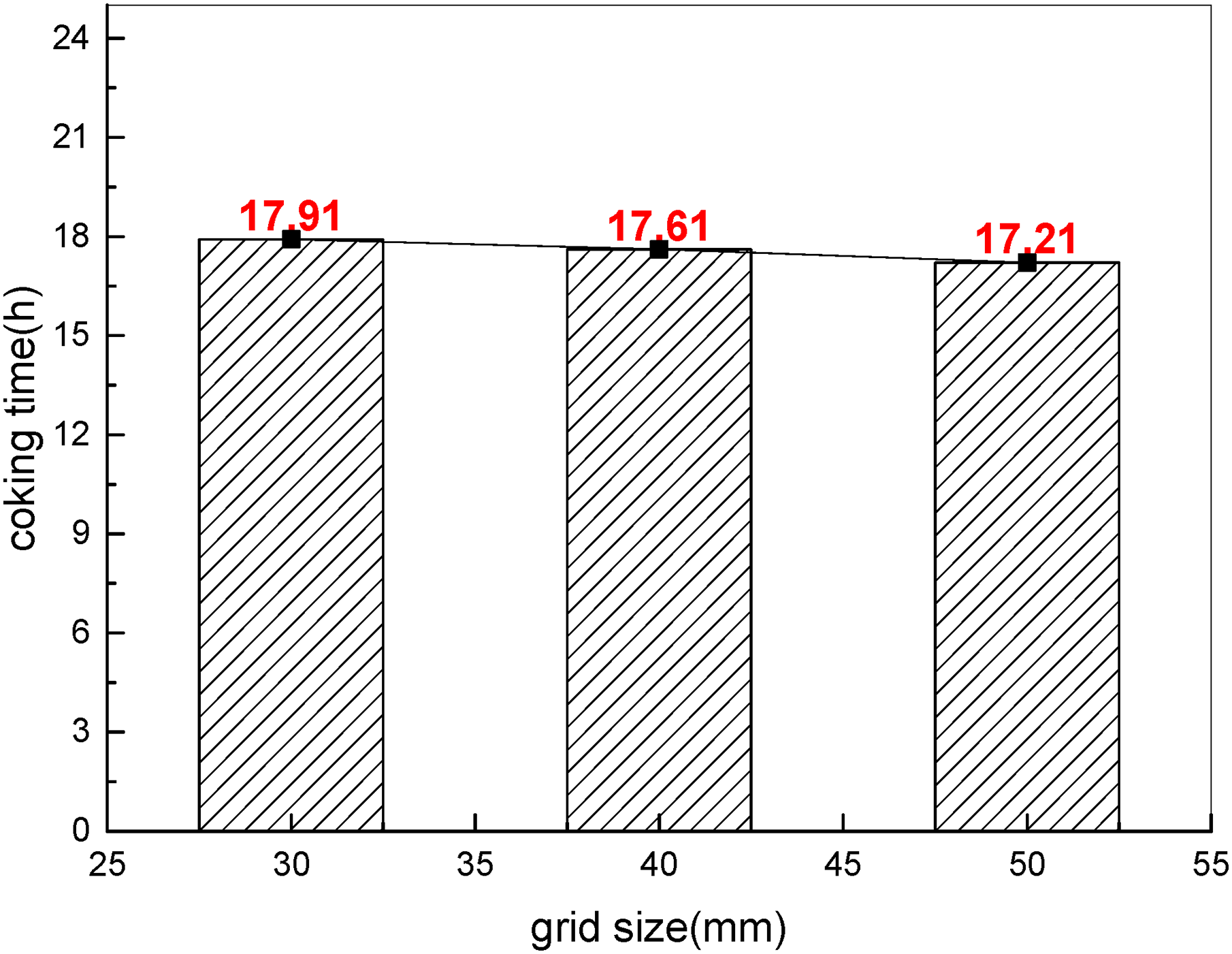
Effect of grid size on coking time of coke oven.
Importantly, the mathematical model and numerical method for the coke oven need to be compared with the basic data provided by the heat balance calculation to validate its reliability, as listed in Table 3. To verify the correctness of the external flue gas recirculation model and compare it with the numerical results in the aforementioned study, the only difference is that the periodic combustion between the vertical flues of the coke oven was not considered. After introducing periodic combustion and external flue gas recirculation, the simulated results of flue gas composition at the outlet were compared with those simulated by Li et al., 30 as well as experimental results, as shown in Figure 7.
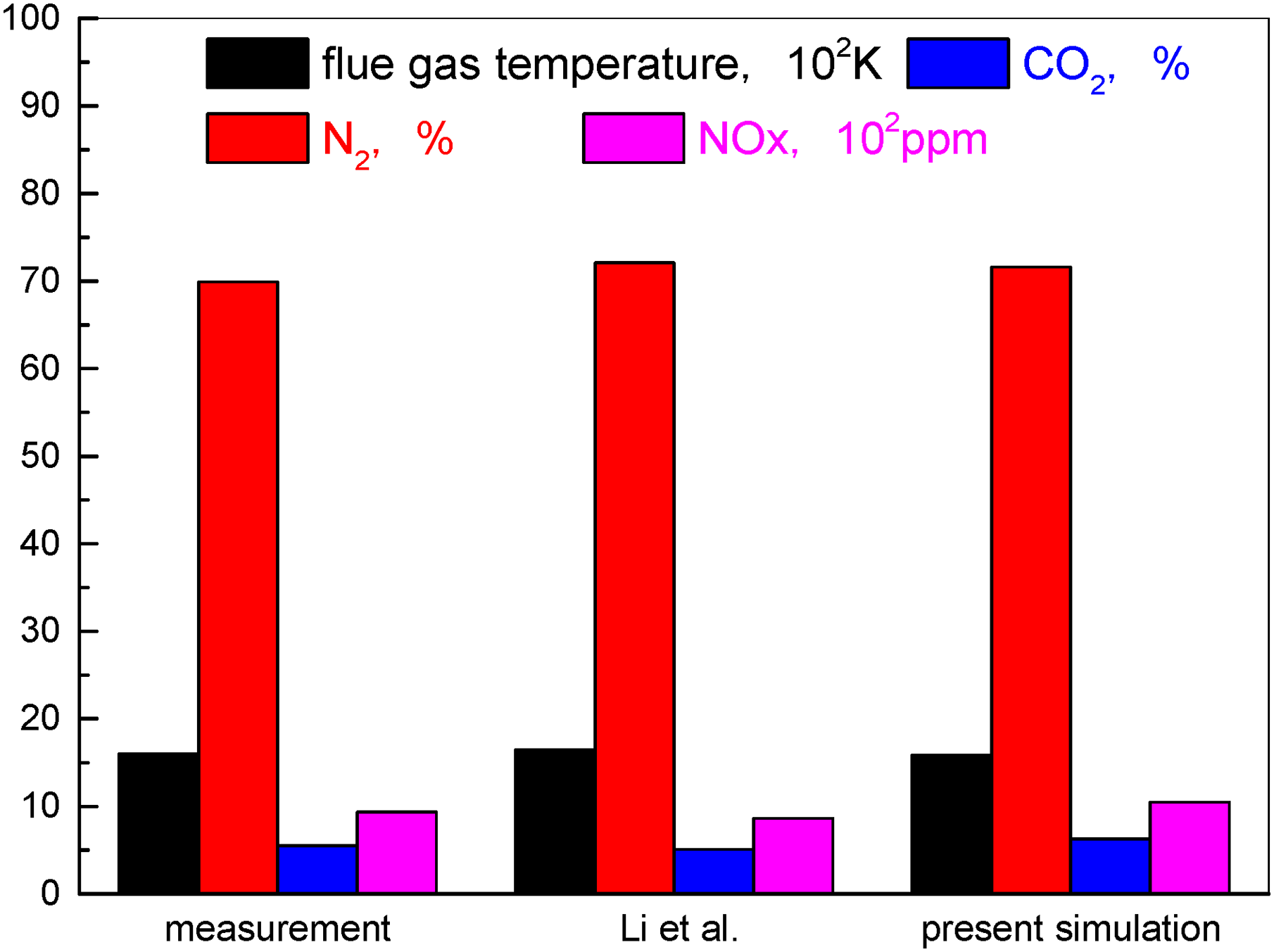
Comparison between simulated and experimental results of flue gas composition at the outlet of coke oven under external flue gas recirculation.
Comparison of numerical results and experimental results of coke oven under external flue gas recirculation.
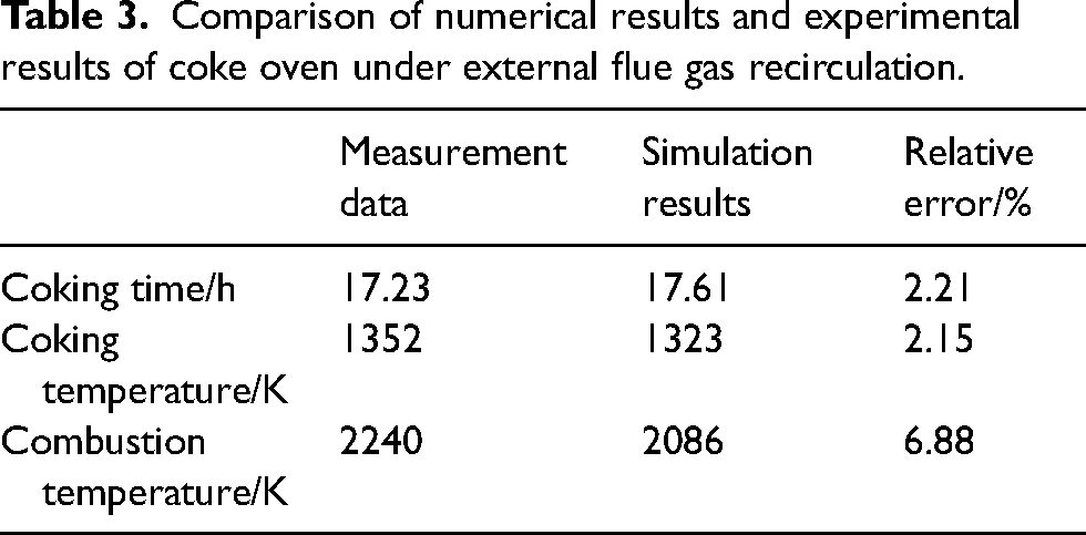
The combustion temperature in this paper is the average temperature of the combustion chamber, while the combustion temperature in the plant test is the theoretical combustion temperature according to the heat balance of the coke oven, so there is a large difference between them, which is about 6.88%. Since the coking temperature of the carbonisation chamber is set as the average temperature of the central plane of the coking coal which reaches 1323 K, the coking time in the simulation is longer than that in the plant test, and the deviation is 2.21%. In addition, Li et al. adopted oxygen-enriched combustion technology for the coke oven, and still the oxidant in the plant test was air, so the combustion temperature simulated by Li et al. is higher and yet the NOx emission is lower. In this article, we introduced the periodically reversal combustion approaches and external flue gas recirculation technology, so that both the flue gas outlet temperature and the NOx emission are lower than those in the experiments.
During the coking process, the combustion temperature of the vertical flue is very important, which determines the temperature uniformity of the coking coal and the formation of thermal NOx. The theoretical combustion temperature in the vertical flue is about 2086 K, and the simulated maximum temperature is in good agreement with the experimental data, with a relative deviation of approximately 6.88%. This further proves the feasibility of the comprehensive model for the coke oven. All in all, the maximum error is less than 10%, which is within the engineering error. This indicates that the mathematical model and numerical method for the coke oven in this paper are reasonable and could further extend numerical analysis with respect to the coking characteristics and coking factors of the heating system.
Coking behaviour of coke oven
Given the detailed discussions on the temperature field, species concentration field and velocity field of the coke oven in existing literature, 26 this section is focused on the temperature history and heat flux profile during periodic non-steady process of the coke oven with external flus gas recirculation. More discussion about the physical field such as temperature contour, velocity distribution and species concentration would be conducted soon. Herein, the temperature profile in the vertical flue of the coke oven for three cycles is visualised in Figure 8. The combustion cycle of the vertical flue is about 25 minutes, simultaneously followed by changing the direction of airflow flow. As gaseous fuel burns with combustion air periodically between the adjacent vertical flue, the ascending and descending flue switches continuously. Due to the gaseous combustion occurring on the ascending flue, the average temperature of the ascending flue is always higher than that of the descending flue. During the same working state of the vertical flue, the average temperature shows an upward trend with the coking time, and the temperature difference between the ascending flue and descending flue gradually decreases to is about 150 K. Notably, during the initial phase of the reversing combustion, the average temperature of the ascending flue would be sharply elevated. This reason is that at the very beginning time, blast furnace gas violently burns with combustion air and a large amount of heat was generated, and then begins to decrease and tends to stabilise, which is ascribed that the periodic combustion appears in the adjacent vertical flue, causing the temperature distribution of the heating flue to be much uniform. Both the ascending flue and the descending flue temperature are jagged, indicating the periodically switching combustion between the adjacent vertical flues. Besides, the upward trend of the sawtooth curve is also obvious, which indicates that the temperature in the heating flue increases with the coking time. In the first three cycles, the ascending flue temperatures were successively about 1687 K, 1695 K and 1702 K, while the descending flue temperatures were respectively about 1689 K, 1697 K and 1704 K, but the ascending flue temperature was lower than the descending flue temperature by about 2 K. Due to the continuous alternating combustion in the front and back combustion chamber, the temperature distribution in the vertical flues was more uniform. Thus, the temperature uniformity of the coking coal in the carbonisation chamber was increased, and the quality of the coal converted to coke was improved.
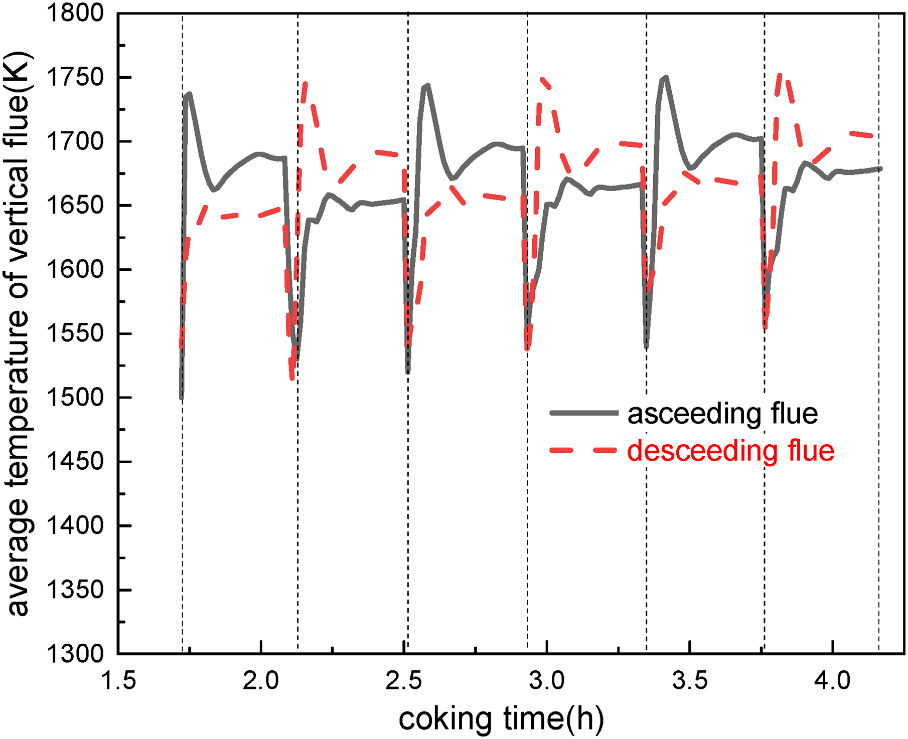
Average temperature of vertical flue for coke oven.
In present work, because the carbonisation chamber was filled with the coking coal, the coking coal was simplified as pure solid phase without porosity, and the physical and chemical change during the coking process were converted into the change in effective physical properties with the coking temperature. In other words, the effective physical properties with the temperature history of the coking coal have been related to the water evaporation and the porosity changes caused by it. This paper focuses on the heat transfer of the coking coal in the carbonisation chamber during the coking process of coke oven. The porosity mainly affects gas generation and flow during the coking process of the coking coal. And the effect of porosity on the heat transfer of the coal distillation process has been transformed into the effective thermophysical properties. Moreover, the coking time and the coking temperature on central plane of the carbonisation chamber are consistent with the actual situation of the coking coal in the coke oven. This also verifies the reasonableness of treating the coking coal as pure solid phase without porosity. The discussions about the carbonisation chamber were limited to the temperature change during the coking process. The heat generated by the gaseous fuel combustion in the vertical flue is mainly transferred to the partition wall through the thermal radiation, and then to the coking coal by heat conduction. In the early coking stage, the latent heat of moisture vaporisation is a little high, and yet the thermal conductivity of the coking coal is relatively low. Therefore, the rise rate of the average temperature on the central plane of the coking coal is a little slow. As the coking coal was heated, the plastic layer began to form on both sides of the carbonisation chamber, resulting in a large amount of moisture vapour entering the wet coal layer. Due to the low temperature of the wet coal layer, water vapour was condensed when encountering it. The moisture content of the wet coal layer increases, and then heating rate of the coking coal slows down. Furthermore, due to the fuel inlet duct of the vertical flue leaning towards the right partition wall, the high-temperature region of the vertical flue also leans towards the right side. The average temperature of the right carbonisation chamber is higher than that of the left carbonisation chamber. After the average temperature of the coking coal reaches around 800 K, the required heat reduces, resulting in a significantly faster heating rate. This behaviour is explained by the plastic layers on both coal sides moving towards the central plane and forming semi-coke and coke on the outside carbonisation chamber, which has high thermal conductivity. In the later coking stage, as the average temperature of the partition wall gradually increases, the temperature difference of the vertical flue gradually decreases. The temperature rise rate of the coking coal gradually decreases, as reported in Figure 9. When the corresponding coking temperature of 1323 K was reached, end coking operation. 9 Hence, the average temperature on the central plane of the carbonisation chamber at the end of the coking process can be used as a sign of mature coke. This temperature is called the final coking temperature. According to the nature of the coking coal and the requirements for coke quality, the final coking temperature is commonly in the range of 1223–1323 K. In this article, it is believed that when the average temperature on the central plane reaches 1323 K, the simulated whole coking time lasts around 17.61 hours, and the actual production time is approximately 18 hours. The consistency between the predicted coking time and the on-site coking time is very good with a relative error of 2.17%. Due to the rapid decline of temperature oscillation caused by the periodic combustion of the vertical flue, it should be noted that the temperature oscillation does not appear on the central plane of the carbonisation chamber.
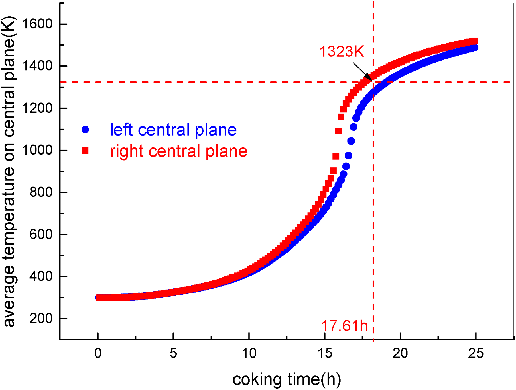
Average temperature on central plane of carbonisation chamber.
The relationship between the average temperature of the vertical flue and the average temperature on the central plane of the carbonisation chamber is pictured in Figure 10. The average temperature of the vertical flue is related to the gas phase combustion in the combustion chamber and the heat absorption of the charging coal in the carbonisation chamber. In the case of periodical combustion, the average temperature of the vertical flue shows a periodic change, firstly an increase and then a decrease. As the average temperature on the central plane of the carbonisation chamber gradually increases, the average temperature of the vertical flue progressively rises periodically. According to the hypothesis, when the coking coal is converted into coke, accompanied by the reaction heat effect, the specific heat of the coking coal reaches a maximum and minimum at about 873 K and about 1073 K, respectively, during the coking process. In the range of 873–1073 K, due to the rapid decrease in the specific heat of the charging coal, the heat absorption of the coking coal declines drastically. Within the same reversing combustion cycle, the average temperature of the central plane of the carbonisation chamber rises faster and to a higher level. The heating time required for the coking coal in this heating zone is shorter, and the reversing number in the combustion chamber is reduced. There is a larger heating range of the coking coal in the carbonisation chamber and a reduction in the number of changes in the periodic temperature in the vertical flue. By monitoring the coking coal temperature during the coking process, if the average temperature of the coking coal in the carbonisation chamber is in the range of 873–1073 K, the gas mass flow rate of the combustion chamber can be increased, thereby intensifying the reaction heat during this coking stage. This would increase the heat required for coking, shorten the coking time, and reduce the NOx emission.
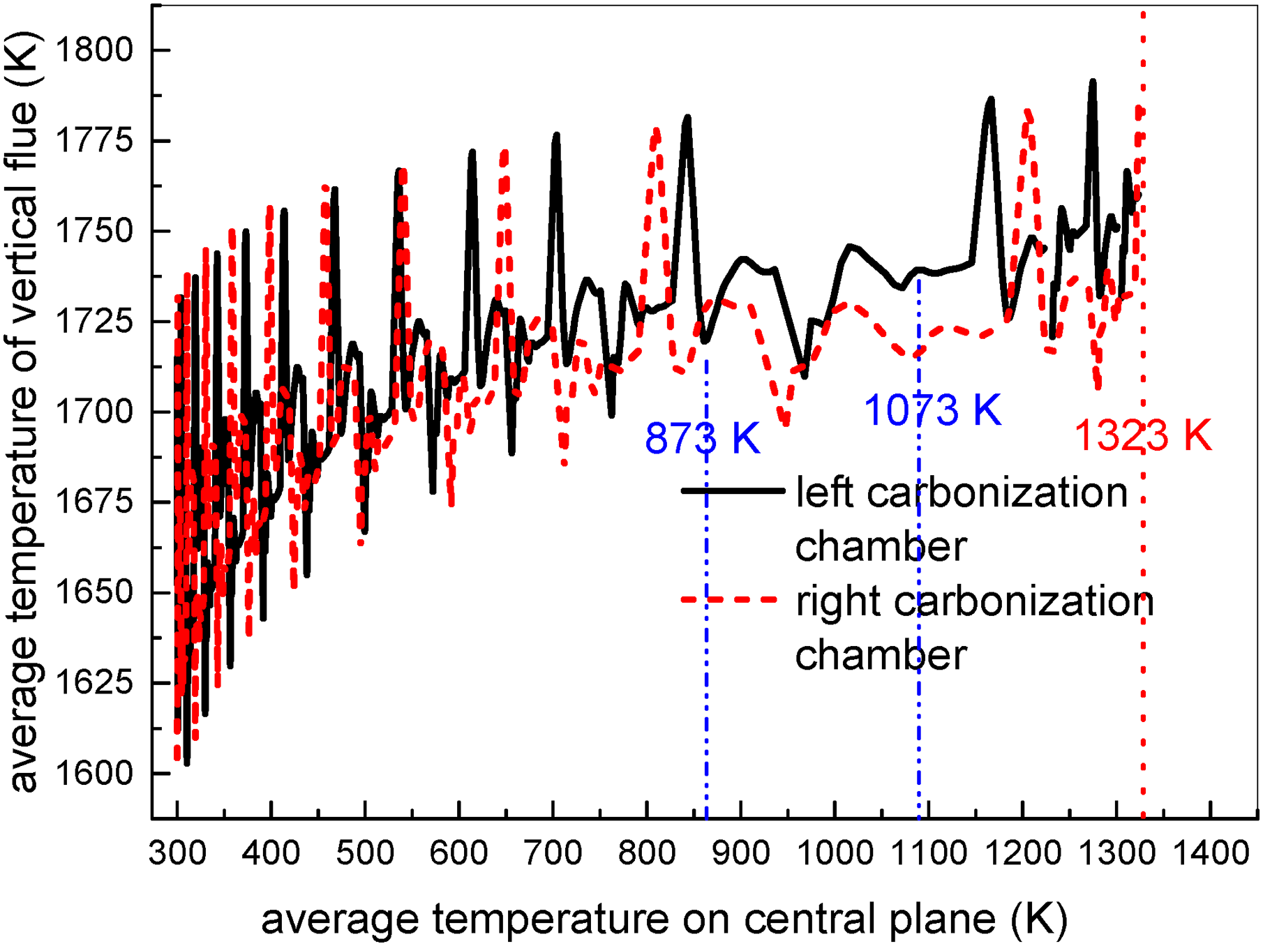
Relationship between average temperature of vertical flue and average temperature on central plane of carbonisation chamber.
The temperature evolution of the coking coal along the width and height direction at different coking times is displayed in Figure 11. The heat generated by gaseous combustion is obviously transferred to the central plane of the carbonisation chamber through the partition wall. It can be clearly seen that the coking coal near the partition wall was rapidly heated, and then heat is transferred through the rest of the coking coal. Moisture evaporation plays an important role in the coking coal temperature. Before the end of moisture evaporation, there would be no obvious temperature rise on the central plane of the coking coal in the carbonisation chamber. When the coking temperature reaches 1323 K at around 18 hours, the temperature uniformity of the coking coal in the carbonisation chamber is significantly improved. It is worth noting that due to the uneven distribution of flue gas temperature in the combustion chamber, the coking temperature in the upper and lower part of the carbonisation chamber along the height direction are higher than those in the middle part. Namely, the coking temperature in the middle part of the coking coal is the lowest, and the highest is in the upper part. The temperature difference along the height direction is not more than 50 K, which meets the requirements of the coke quality. The carbonisation chamber is subjected to the heat transmitted by the partition wall. The coking coal in the carbonisation chamber was gone through pyrolysis, depolymerisation to form metaplast, solidification to semi-coke, and polycondensation, ultimately carbonisation into coke. After the metaplast formation of the coking coal in the carbonisation chamber, the heat transfer capability becomes weak. Therefore, there is a significant temperature gradient at different locations of the coking coal. The coking status of the coking coal with different distances from the partition wall of the carbonisation chamber is different. Accordingly, each layer of the coking coal in the carbonisation chamber is heated by different modes. The coke firstly forms near the partition wall, and then gradually moves toward the central plane of the carbonisation chamber, which is called coking. In a word, the physical and chemical processes such as moisture evaporation, volatile matter release, softening, melting and bonding of the coking coal in the carbonisation chamber until the semi-coke is solidified, and then the semi-coke shrinks and ultimately turns into coke. The specific coking process is divided into three stages, namely, the drying and desorption stage of the coking coal from room temperature to about 573 K, the pyrolysis and contraction stage of the coking coal above 573 K to about 873 K, and the coking coal from semi-coke to coke above 873 K to about 1273 K. Generally, the simulated results show that the developed model correctly reproduces the various stages of the coking process inside the coke oven.
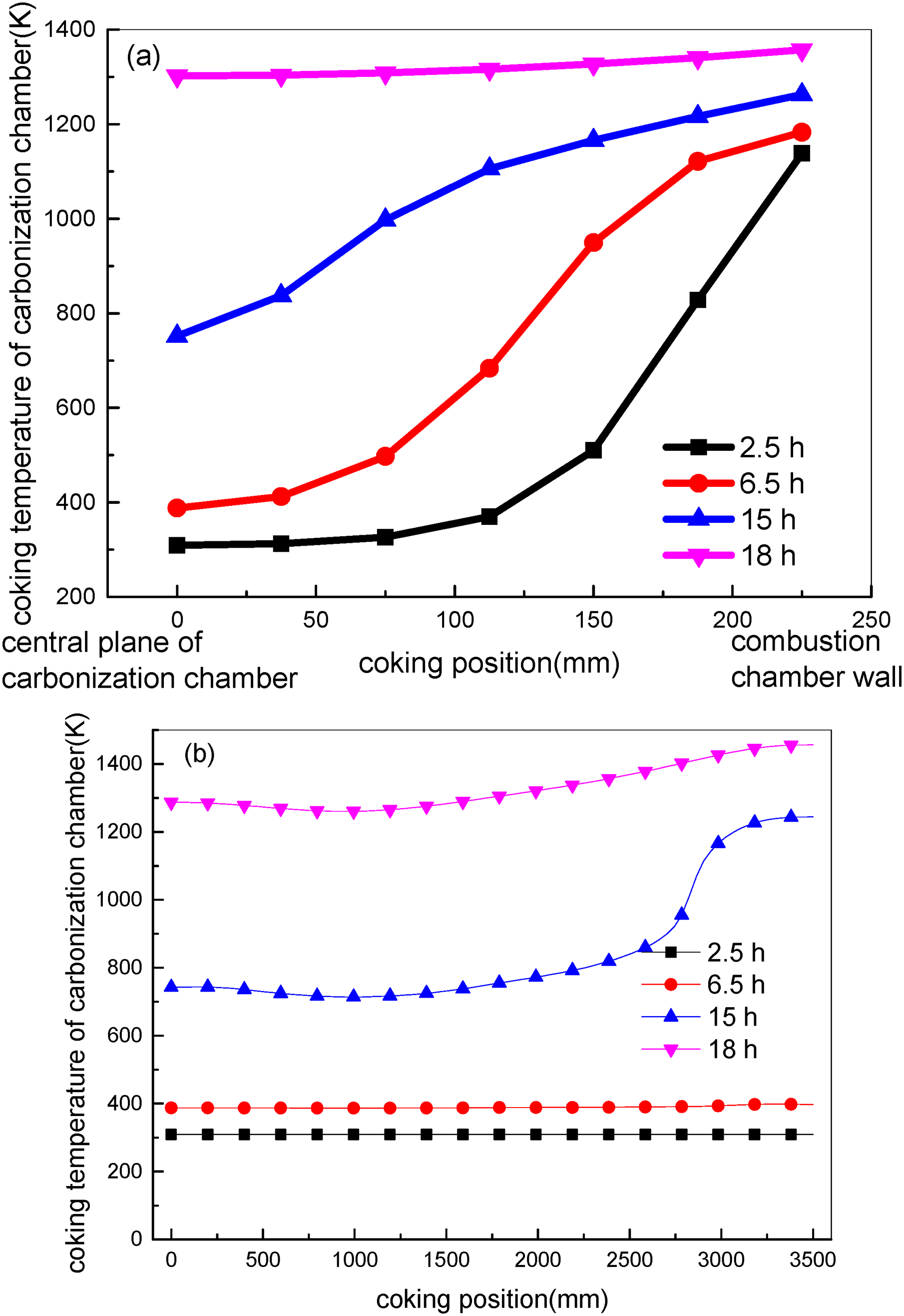
Coking coal temperature profile along width direction (a) and height direction (b) at different coking times.
As for the heat flux on the walls in contact with the coking coal during the coking process of the coke oven, the initial temperature was set as 1400 K and 300 K for the partition wall and the coking coal, respectively. This would result in a sharp decrease in heat flux between the coking coal and the partition wall at the initial coking time. Due to the periodic combustion in the adjacent vertical flue, there is a continuous increase in the temperature on the coal side, and the temperature difference on both sides of the partition wall decreases periodically. It would lead to periodic decay in the heat flux at the left and right interface between the partition wall and the carbonisation chamber. In general, in the early coking stage, the coking temperature of the coking coal in the carbonisation chamber is relatively low, while the gaseous temperature on another side is considerably high. There is greater heat transfer driving force, which rapidly heats up the coking coal near the partition wall. Due to the lack of significant changes in the gaseous temperature inside the combustion chamber, the temperature difference on both sides of the partition wall rapidly decreases, which is represented significantly drop in the heat flux. Hence, the heat absorbed by the carbonisation chamber from the combustion chamber gradually decreases. In the intermediate stage coking stage, due to the rapid increase in the coking temperature of the coking coal near the partition wall, the coking temperature of the coking coal is very close to the temperature of the partition wall, so the heat transfer rate reduces, and the rate in temperature difference and heat flux on both sides also slows down. In the final coking stage, the coking coal in the carbonisation chamber is converted into coke. As a result, heat required for heating up the coking coal is significantly reduced after stopping coking. Moreover, the thermal conductivity increases, while the specific heat decreases. In the same heat transfer environment, the heating rate of the coking coal becomes faster, and the temperature of the coking coal would be higher, while the gas combustion temperature does not change much. Thus, a gradual decrease in heat flux on both sides of the partition wall indicates that the coking process is about to end. The temperature difference on both coal sides decreases with the coking time and tends to be stable, and the heat flux also gradually stabilises, as illustrated in Figure 12, which is contrary to the temperature evolution. In addition, the heat flux of the left interface is lower than that of the right interface, which is in agreement with the temperature evolution of the carbonisation chamber.
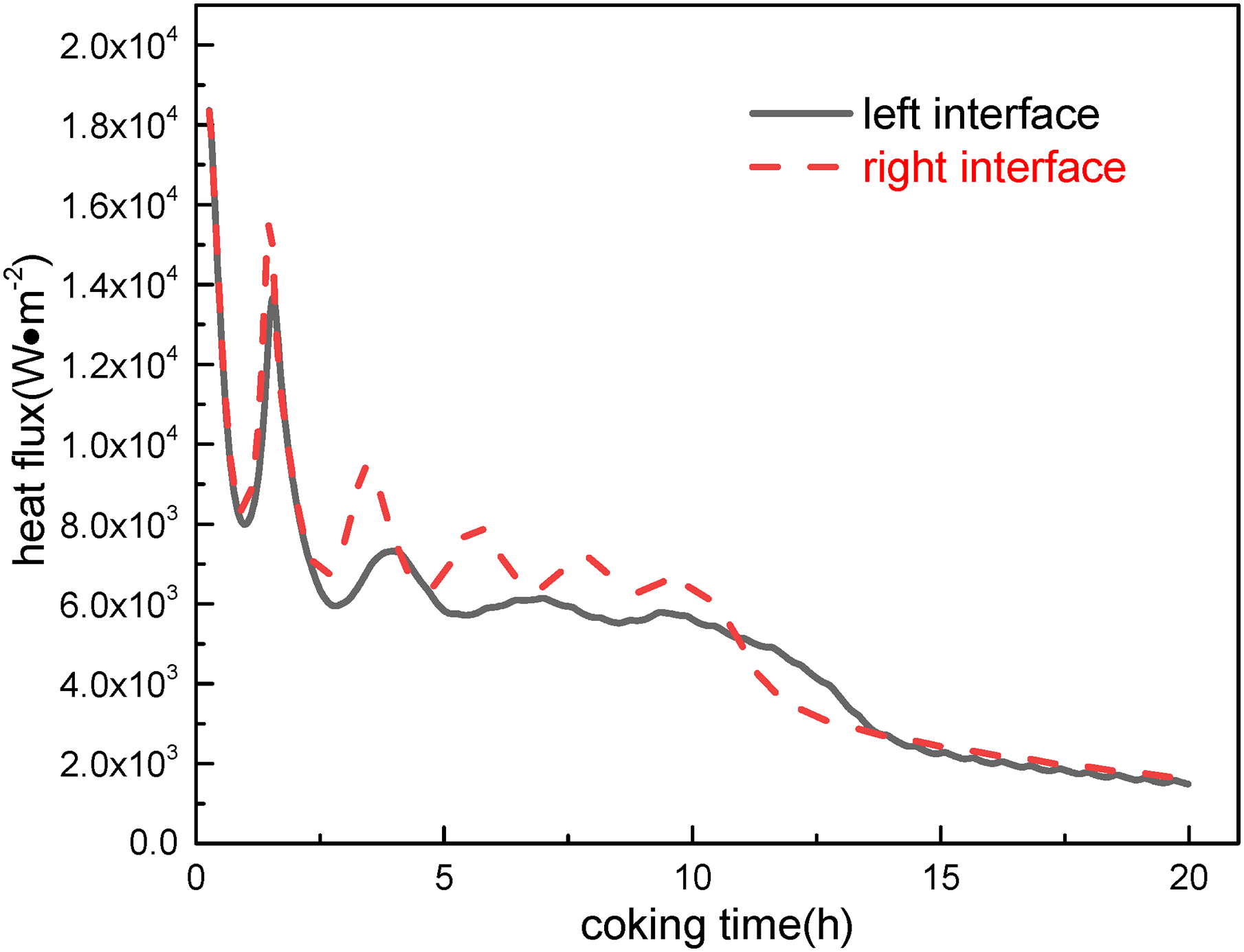
Heat flux profile between carbonisation chamber and partition wall with coking time.
Coking factors of coke oven
Reversing period
In the coking industry, the operation parameters of the coke oven were commonly adjusted to obtain energy-saving, emission reduction and high-quality coke. Based on the other previous theories and results, the effects of reversing period and external flue gas circulation ratio on the coking behaviour of the coke oven need be further concerned. Due to the consideration of periodic firing between the adjacent vertical flue in this study, the ascending flue and descending flue switched periodically with the reversing period, thus the flue temperature changes periodically. The longer the reversing period, the longer the combustion time in the vertical flue. There is a remarkable difference in the average temperature between the ascending flue and descending flue throughout the coking cycle. Whereas the average temperature of the vertical flue slightly increases in the same cycle with the increase of the reversing period, as shown in Figure 13. In a word, the reversing period brings out little temperature fluctuation inside the vertical flue, and the generation content of thermal NOx is directly related to the combustion temperature, so it may predict that the generation rate of thermal NOx remains nearly constant under different reversing periods. However, as the reversing period increases, the final coking time shortens. Therefore, the total amount of NOx would reduce during the entire coking cycle.
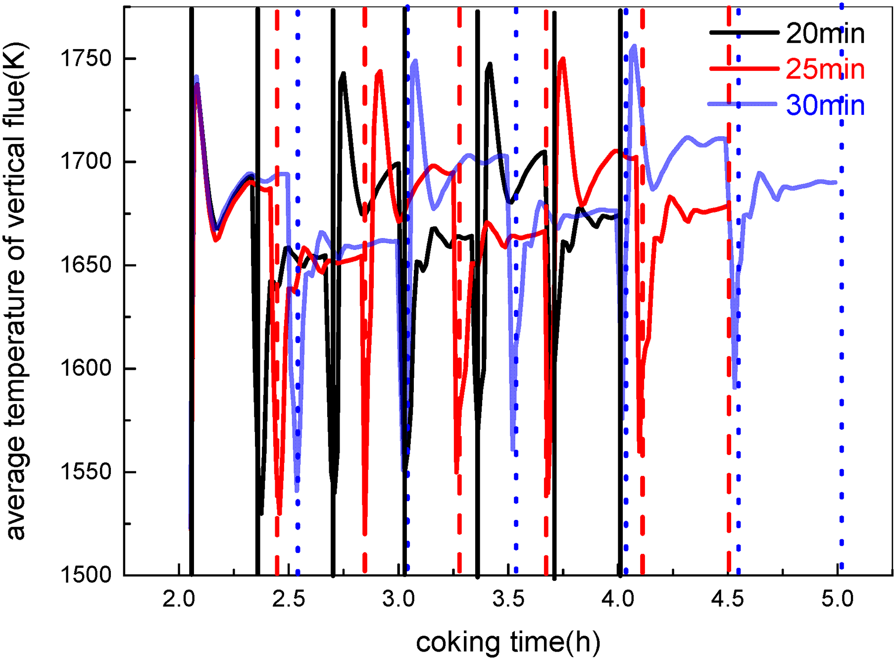
Average temperature of vertical flue under different reversing periods.
Figure 14 gives the average temperature on the central plane of the coking coal under different reversing periods. The average temperature of the vertical flue slightly increases on account of the increasing reversing period, and much heat transmitted through the partition wall increases. Thus, there is a faster temperature rise of the coking coal in the carbonisation chamber. The average temperature on the central plane of the coking coal increases with the increase of the reversing period. Eventually, the coking time required for the final coking temperature decreases with the increase of the reversing period. It may be speculated that increasing the reversing period can reduce the entire coking time, and further save energy consumption.
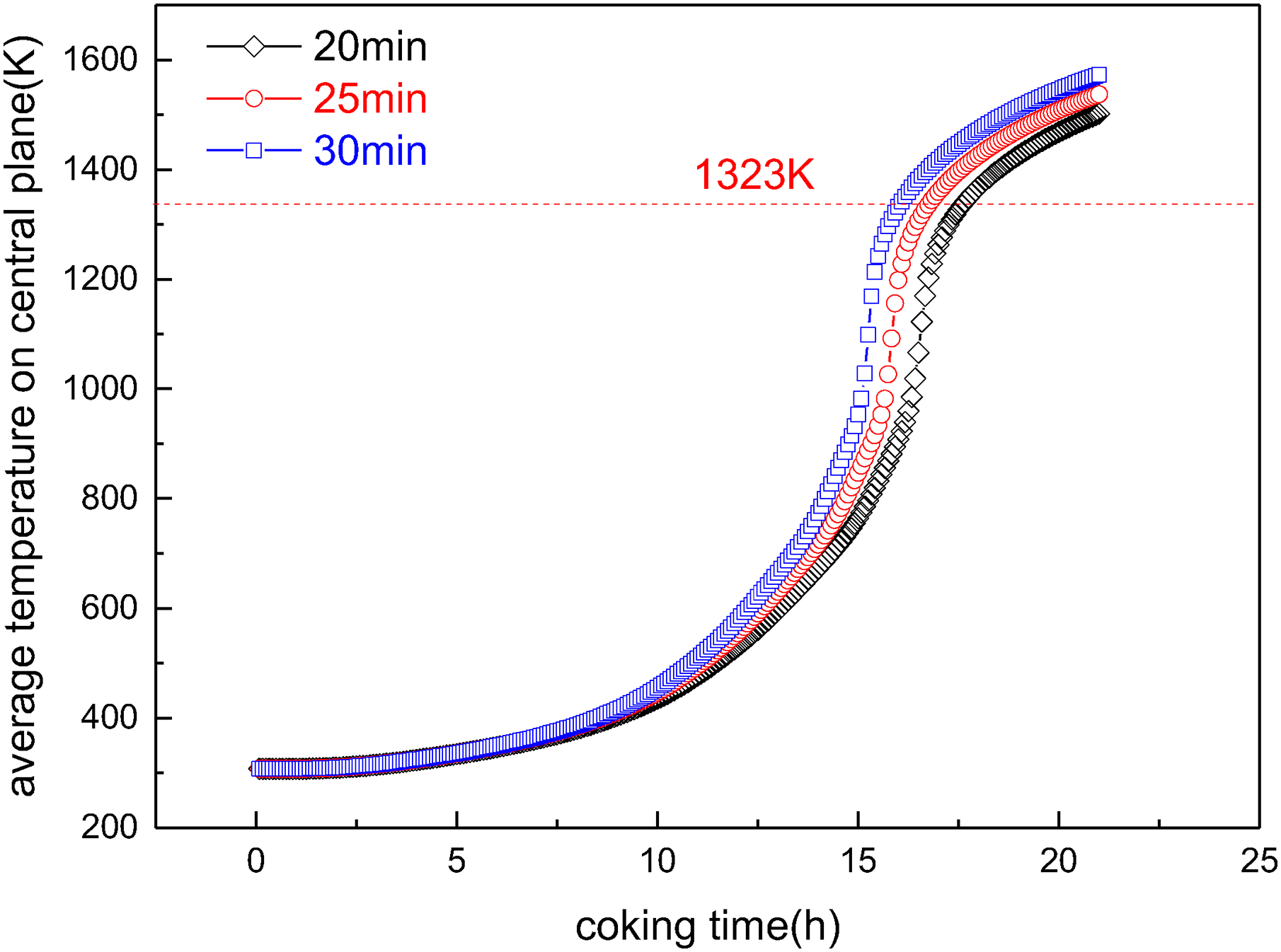
Average temperature on central plane of carbonisation chamber under different reversing periods.
As the reversing period increases, the maximum temperature and minimum temperature of the coking coal on the central plane slightly decreases, and yet the maximum temperature difference increases, as presented in Figure 15. As the reversing period increases, the heat transfer of the coking coal in the carbonisation chamber becomes weak. There is a significant decline in the temperature uniformity of the coking coal, thereby affecting the coke quality. After all, since the temperature fluctuation was inevitably by the alternately periodic combustion, the shortened reversing period causes the gaseous combustion to quickly shift towards another vertical flue before hot gas achieves more heat in the vertical flue. Ultimately, there is a smaller temperature difference in the carbonisation chamber.
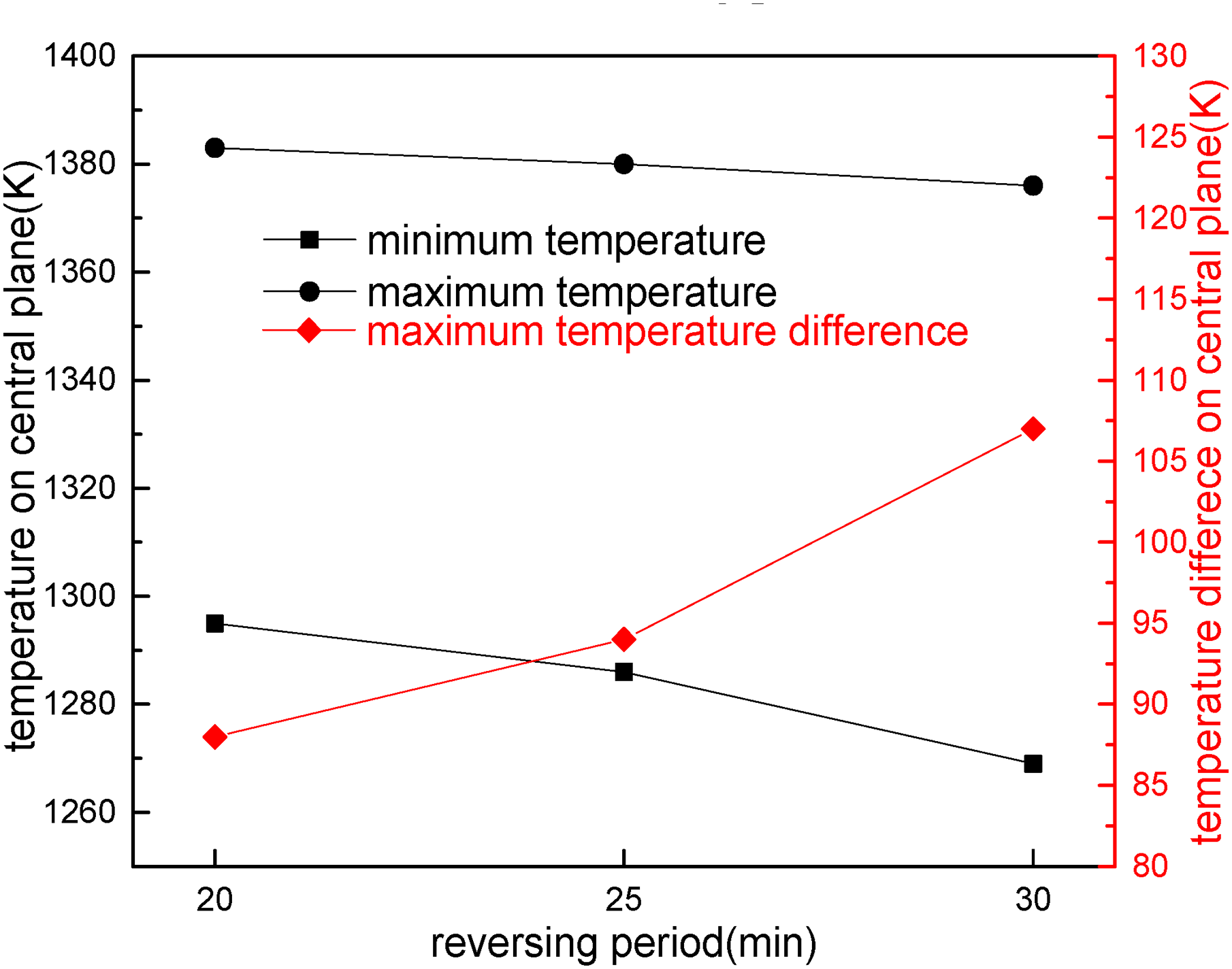
Maximum temperature, minimum temperature, and temperature difference on central plane of carbonisation chamber under different reversing periods.
Overall, these findings demonstrate that there is a trade-off between the coking time and the uniformity of temperature distribution at different reversing periods. The coking time not only affects the coke output, but also directly determines the heat consumption of the coke oven. The coking time of the coke oven is influenced by various factors, including the geometry dimensions of the carbonisation chamber, the gas temperature in the vertical flue, the thickness and thermal properties of the partition wall, as well as the processing characteristics of the coking coal, such as water content, initial density, preheated temperature and coal-blending ratio. When the carbonisation chamber is widened, there is an increase in the coke output. However, because the heating source of the charging coal comes from the partition wall, the more heat is required for coking, the longer coking time, which would result in a subsequent reduction in the production capacity. The thicker partition wall or the lower thermal conductivity, the greater the thermal resistance. This would lower the heat transfer rate from the combustion chamber to the carbonisation chamber, which would prolong the coking time to meet more heat consumption.
Slow heat transfer may be improved by reducing the width but increasing the height. A narrower coke oven would reduce the distance that heat travels across the width of the coke oven, theoretically increasing the heat transfer rate and thus reducing the coking time. However, an increase in the height can present some challenges. A taller coke oven means that the heat needs to travel longer vertical distance, which would result in a lower heat transfer efficiency and therefore an increase in the coking time. In short, the effectiveness of this design depends on the combined effect of width and height variations on the heat transfer rate. As the height of the coke oven increases, the amount of reactive gases in the oven also increases. Regenerative combustion technology facilitates a more even distribution of gas reaction heat, thus favouring uniform heating of the coke, while flue gas recirculation can influence the heat transfer rate by the combustion temperature and gas composition. However, excessively high coke oven would lead to increased gas velocities within the carbonisation chamber, increasing the instability of the coking coal and thus affecting coke yield. In summary, a narrower but taller coke oven can theoretically help to reduce coking time, but the actual effect depends on a few factors such as combustion technology and flue gas recirculation strategy. Detailed engineering analysis and experimental validation are required to accurately assess the feasibility of this design.
The higher the water content in the coking coal, the more heat must be absorbed by water evaporation, which not only prolongs the coking time and increases heat consumption, but also reduces the coke quality. If the water content of the coking coal is below 6%, the coal density is increased, the coking time is shortened, the production capacity of the coke oven is increased, and the coke quality is improved. In addition, the preheated coal may increase the amount of gas coal, raise the production capacity of the coke oven, and improve the coke quality. By reducing the heat absorption of the furnace wall, the heat consumption is reduced, but the charging technology is complicated and costly. The vertical flue temperature depends on the calorific value, the preheated condition, and the air–fuel ratio. The higher the preheated gas temperature, the higher the vertical flue temperature. When the air–fuel ratio is relatively low, the combustion is incomplete, the combustion temperature is not high, and the amount of flue gas increases. On the contrary, while the air–fuel ratio is too high, the amount of exhaust gas would be large, increasing the heat removal of the oven gas and chemical products, and then reducing the thermal efficiency of the coke oven. Besides, according to the gas combustion depending on the mixing characteristics between gas fuel and air, the slow mixing of air and gas fuel can reduce the combustion speed and extend the combustion flame, thus improving the heating uniformity of the coking coal along the high direction. Consequently, advanced heating methods for the coke oven are adopted, such as high-density silicon bricks, mixed fuel combustion, multi-point heating and exhaust gas recirculation, coal pre-treatment technology, that is, blending, moistening and stamping, etc., to enhance the heat transfer process of the coke oven, lengthen the combustion flame, and then ensure uniform conversion of the charging coal in the carbonisation chamber into coke. To summarise, all factors must be considered to determine the optimum coking time. For the current regenerative coke oven, the 25 minutes of the reversing period has been found to be the most effective coking time. This is that because the vertical flue with higher temperature enhances heat transfer, resulting in a better temperature uniformity of the coking coal in the carbonisation chamber.
External flue gas recirculation ratio
It could be apparently observed from Figure 16 that without external flue gas recirculation, the average temperature of the vertical flue changes smoothly, and the difference temperature between the ascending flue and descending flue is relatively small. With external flue gas recirculation, the changes are unstable and have a little high disturbance. The reason for this is that when external flue gas recirculation was not adopted, the mass flow rate, temperature, and mass fraction of each species at the inlet remain unchanged. However, when external flue gas recirculation technology was applied, the temperature and mass fraction of the mixed gas inlet were recalculated in every iteration, resulting in the unstable gas temperature of the vertical flue. By comparing the average temperature of the vertical flue with different external flue gas recirculation ratios, the increase of the external flue gas recirculation ratio can reduce the average temperature of the vertical flue. The mean flue temperature without external flue gas recirculation is about 80–130 K higher than that with the external flue gas recirculation ratio of 20%. Consequently, the external flue gas recirculation technology effectively reduces the average temperature of the vertical flue, which would prolong the final coking time, resulting in increased energy consumption.
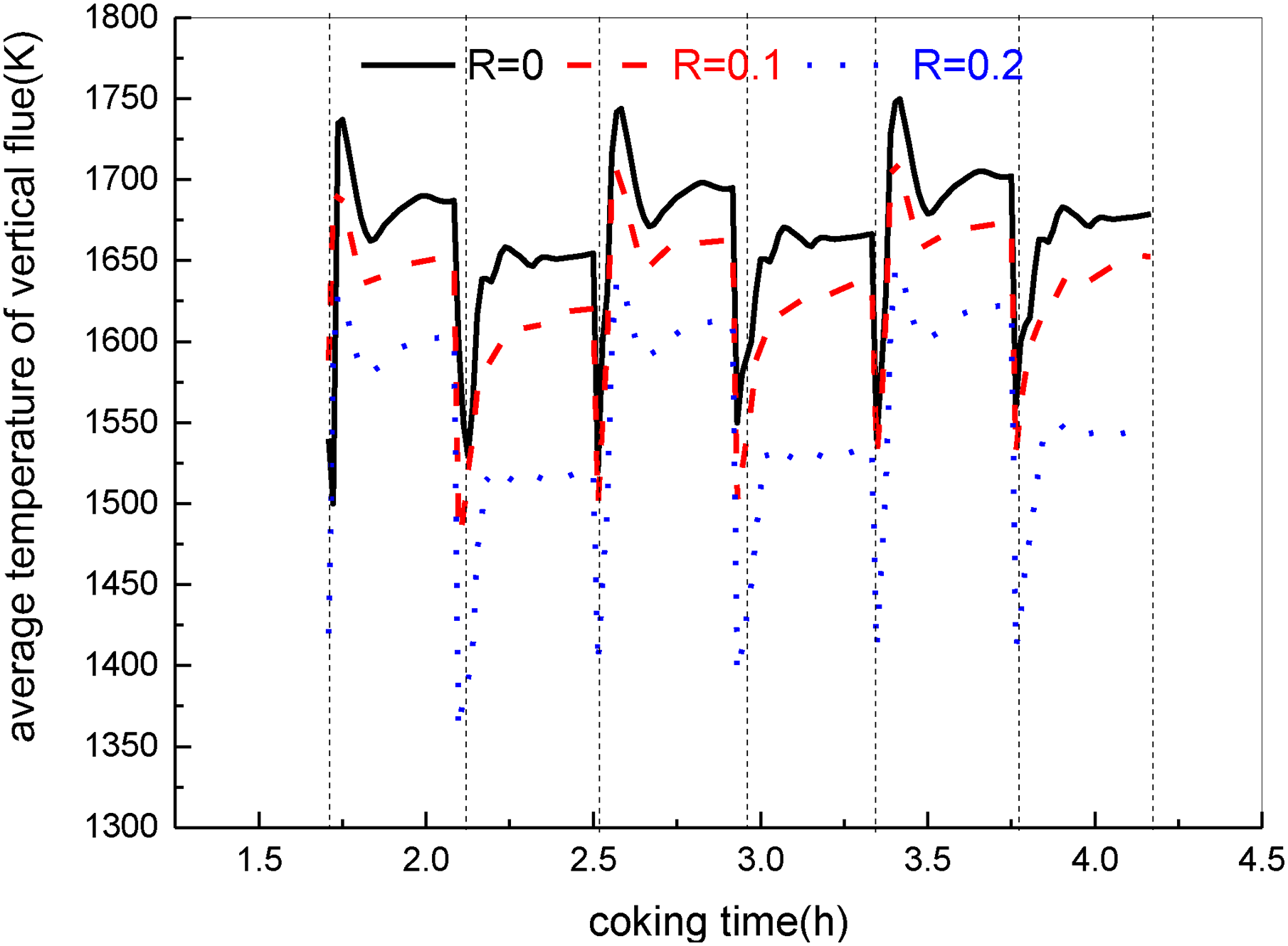
Average temperature of vertical flue under different external flue gas recirculation ratios.
In Figure 17, due to the recirculation effect of low-temperature flue gas and the high content of three atomic gases in flue gas such as CO2 and H2O, these gases are opaque to the thermal radiation. Therefore, as the external flue gas recirculation ratio increases, the amount of exhaust gas entering the vertical flue becomes more, the mass flow rate of flue gas from the vertical flue increases, and the maximum temperature of the vertical flue gradually decreases, suppressing the formation of thermal NOx. This is due to the increase in the external flue gas recirculation ratio, which leads to an increase in CO2 concentration in the flue gas. Nevertheless, the specific heat of CO2 is higher than that of N2, giving rise to lower the combustion temperature of the vertical flue. On the other hand, the increase of CO2 causes a decrease in mass fraction of O2, so the higher external flue gas recirculation may be abandoned to avoid lowering flue temperature. It is not good for the carbonisation of the coking coal. Generally, the generation content of thermal NOx is mainly affected by combustion temperature. With the decreasing combustion temperature, it decreases exponentially, achieving low NOx concentration in the atmosphere from coking production. Especially, when the combustion temperature is above 1800 K, it is more sensitive to combustion temperature and has a significant contribution to the formation of thermal NOx, thereby reducing the generation rate of thermal NOx, which is harmful to the atmosphere. The maximum temperature of the vertical flue without external flue gas recirculation decreased from 2086 K to 1932 K when 20% of flue gas was recirculated, a reduction of approximately 154 K. The average concentration of NOx at the outlet decreased from 1150 mg/m3 to 130 mg/m3, with a decrease of about 89%. It meets the latest emission standards of the coking industry, which is below 100–150 mg/m3 (about 200–300 ppm). Considering the coking time of the coking coal in the carbonisation chamber, if the external flue gas recirculation ratio can be effectively controlled, it not only promotes environmental protection but also does not affect coking efficiency. Additionally, the recirculating exhaust gas would blow away gas and air, causing the diffusion of combustible gas to slow down, thereby elongating the combustion flame and stretching the temperature field along the height direction. This would help to evenly transfer heat to the coking coal in the carbonisation chamber, which would improve the coke quality.
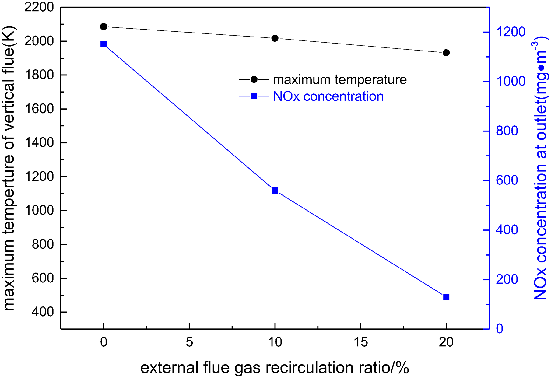
Relationship between the highest temperature of vertical flue and NOx concentration at the outlet under different external flue gas recirculation ratios.
Because the external flue gas recirculation ratio increases, the combustion temperature in the vertical flue decreases. The heat received by the coking coal gradually decreases, and the temperature rise rate of the coking coal decreases with the increase of the external flue gas recirculation ratio, resulting in a longer coking time to reach the final coking temperature of 1323 K, and more energy consumption, as seen from Figure 18. Although increasing the external flue gas recirculation ratio can effectively reduce NOx emissions, the coking time of the coke oven was prolonged, which increases energy consumption. Therefore, it should combine these factors and select an appropriate external flue gas recirculation ratio. In the elsewhere literature, 32 the recirculation ratio ranging from 20% to 25% was recommended for the heating system.
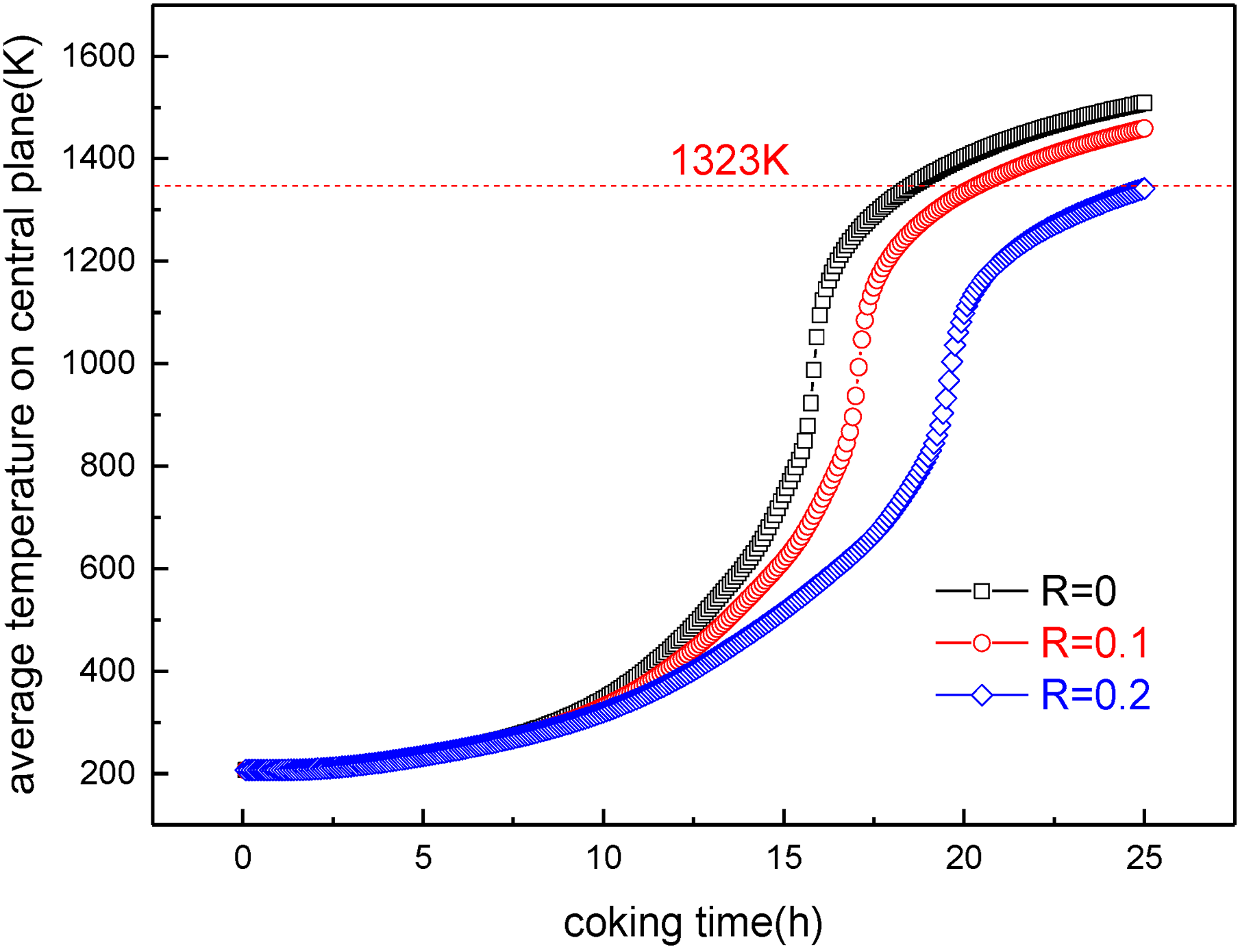
Average temperature on central plane of carbonisation chamber under different external flue gas recirculation ratios.
In this article, only the coupled numerical simulation of the combustion chamber and carbonisation chamber of the traditional regenerative coke oven with external flue gas recirculation, which is a key part of the coke oven heating system, is carried out. Future work would further improve the heating model of the coke oven based on the heat transfer model in the present study, and establish a more detailed comprehensive model for the carbonisation chamber, combustion chamber, and regenerative chamber, which are interconnected with the interactive working conditions. In this way, the mathematical model can represent the gas phase cycle process of the entire coke oven heating system and obtain information such as the relationship between the inlet temperature of the regenerative chamber and the coking time of the carbonisation chamber, the influence of gas species and inlet temperature of the regenerative chamber on the concentration of pollutants in exhaust gas from the combustion chamber. More importantly, the operating parameters of the coke oven can be evaluated, such as air–fuel ratio, gas inlet temperature, gas mass flow rate, mixing gas ratio, air–fuel inlet positions, gas volume distribution ratio, as well as the thermal conductivity of silica brick, initial coal density and initial coal temperature and so on. It is worth noting that the stamping coking technology can save resources and reduce costs. The charging coal density would been significantly improved, from 0.74 ton/m3 for top-loading coal to 1.1 ton/m3, expanding the amount of gas coal while maintaining coke strength to meet the coking requirements. The density of the coking coal affects the thermal conductivity of the coke, particularly for stamping coking of preheated charging coal. As a result, the temperature history pattern of the coking coal in the carbonisation chamber would inevitably be different at different reversing period in stamped charged operations. Future investigations should focus on these aspects, as their results would have great practical significance for the coking industry.
Conclusions
Based on existing models, coupled with the reversing mode and external flue gas recirculation model, combined with temperature-dependent properties during the coking process of the coke oven, the coking behaviour of the coke oven is numerically studied. The effects of the reversing period and the external flue gas recirculation ratio on the coking behaviour of the coke oven were examined. The following conclusions were drawn:
Change in the average temperature of the vertical flue shows periodically alternately, and when the average temperature of the coking coal in the carbonisation chamber increases to around 800 K, the temperature rise rate of the coking coal suddenly increases, and then gradually decreases. While the reversing period increases, the average temperature of the vertical flue gradually slightly increases, and the coking time decreases, but the temperature uniformity of the coking coal deteriorates. As the external flue gas recirculation ratio increases, the average temperature of the vertical flue decreases, and the highest combustion temperature also gradually decreases. The NOx concentration at the outlet decreases, and yet the coking time increases.
Footnotes
Acknowledgements
This article is supported by Provincial College Student Innovation Training Program (S202210360413), Open Project Foundation of Anhui Province Key Laboratory of Metallurgical Engineering & Resources Recycling (SKF22-05), and Natural Science Foundation of Anhui Province (1708085ME108).
Declaration of conflicting interests
The authors declared no potential conflicts of interest with respect to the research, authorship and/or publication of this article.
Funding
The authors disclosed receipt of the following financial support for the research, authorship and/or publication of this article: This work was supported by the Provincial College Student Innovation Training Program, Open Project Foundation of Anhui Province Key Laboratory of Metallurgical Engineering & Resources Recycling and Natural Science Foundation of Anhui Province (grant numbers S202210360413, SKF22-05, 1708085ME108).