
Abstract
To investigate the interaction between low-carbon low-silicon Al-killed molten steel and the refractory materials employed in refining ladles, the study focused on the interface reaction between molten steel with a composition of Fe-0.03C-0.01Si-0.2Mn-0.03Al (wt%) and the four types of refractory materials used in different positions of refining ladles at 1873 K. The results show that different interface layers form after 60 min of contact between the refractory materials and the molten steel. The MgO-C refractory generates a dense MgO layer, the MgO-Al2O3 refractory produces a (Fe, Mg)Al2O4 layer, the Al2O3-SiC refractory forms a Mg Al2O4 layer rich in Si, and the MgO-Al2O3-C refractory generates a MgAl2O4 spinel layer. The average content of Mg at the interface decreases in the following order: MgO-C, MgO-Al2O3-C, Al2O3-SiC and MgO-Al2O3 refractory, and SiC available in Al2O3-SiC refractory supplies more Si to the interface. The thermodynamic simulation is consistent with the actual results.
Introduction
Refractory materials are crucial to the steel industry's refining process. To endure the extreme conditions in the refining process, a range of refractory materials are utilised in different segments of the refining ladle. These include MgO-C brick, MgO-Al2O3-C brick and MgO-Al2O3 refractory materials.1–4 Refractory materials within the refining ladle will be in direct contact with molten steel during the refining process. The reaction between refractory materials and molten steel can result in corrosion and structural spalling of the refractory,5,6 ultimately impacting the composition, inclusion and performance of the molten steel.7–10 Therefore, a thorough understanding of the interaction between refractory materials used in refining ladles and low-carbon low-silicon Al-killed molten steel is essential to optimising the refining process and improving product quality.
The dissolution of refractory materials into molten steel has been thoroughly studied by scholars. Some elements in refractory materials dissolve into molten steel, creating pollution. Liu et al.11,12 examined the dissolution behaviour of Mg, Cr and C in Al-killed steel by studying MgO-Cr2O3 and MgO-C refractories, and they concluded that the amount of Mg dissolved in the molten steel from MgO-C refractory is related to the C and Al content in the refractories. Ren et al. 13 investigated the dissolution behaviour of Mg and Ca in dolomite refractory into molten steel and discovered that MgO in dolomite refractories would reduce due to the presence of Al in molten steel, while Ca content remained mostly unchanged. Furthermore, refractory materials impact the O content of molten steel.14,15 Wei et al. 16 conducted in situ decomposition of limestone that contained CaO refractory. This research revealed that the CO2 produced during high-temperature limestone decomposition reacted with Mn in steel, leading to oxygenation and carburisation.
Additionally, a crucial research focus is the ability of the interfacial layer to obstruct the infiltration of molten steel into the refractory, as well as the effect of the refractory's spalling behaviour on the molten steel. Chen et al. 17 investigated the interaction between Al-killed steel and Al2O3-MgAl2O4 refractory when infiltrated by molten steel. The research found that at the slag-refractory interface, the combination of Al2O3-MgAl2O4 refractory and molten steel created a barrier referred to as the iron-containing spinel layer and iron reaction product layer, which impedes direct mass transfer between the two materials. Kong et al. 18 discovered that [Mn] from Al-killed medium-Mn steel would interact with the MgO-Al2O3 refractory to form the (Mn, Mg)O·Al2O3 complex layer on the surface of the refractory, and effectively controlling the spalling of the (Mn, Mg)O·Al2O3 interface layer can thus control the amount of this type of foreign inclusion in steel. Wang et al. 19 investigated the interfacial reactions among high-Mn high Al steel, MgO-C refractory and refining slag. The research discovered an interface layer composed of spinel and a transition layer composed of the CaO-Al2O3 phase, along with trace spinel and MgO particles. Additionally, Mg-rich inclusions have been observed. The study above demonstrates that the composition of both refractory materials and molten steel affects the composition of the reaction interface. Nevertheless, there are limited studies on the reaction behaviour between low-carbon low-silicon Al-killed molten steel and refractory materials.
This study aims to examine the reaction behaviour of low-carbon low-silicon Al-killed steel when it comes into contact with various refractory materials utilised in refining ladles and to elucidate the interaction mechanism between them. The research contributed to optimising the selection and application of refractory materials in the steel refining process, resulting in improved production efficiency and steel product quality.
Experimental
Raw materials
The refractory materials used in this experiment are the bricks used in various parts of the ladle during the secondary refining process in a domestic steel mill. These bricks include MgO-C brick for the slag line, MgO-Al2O3 brick and Al2O3-SiC pasted brick for the wall coating, and MgO-Al2O3-C brick for the bottom coating. Figure 1 shows the masonry structure diagram of the ladle. Significantly, the three phase coexistence of refractory, molten steel and slag at the slag line. The corrosion of molten steel in the MgO-C brick region was studied in this article without considering the presence of slag. In the initial ladle design, MgO-Al2O3 brick served as ladle wall bricks and made direct touch with the molten steel. Subsequently, the Al2O3-SiC brick is pasted to the surface of the MgO-Al2O3 brick in order to decrease the corrosion of the MgO-Al2O3 brick caused by molten steel. The composition of the refractories was examined using an inductively coupled plasma atomic emission spectrometer (ICP-AES, IRIS Advantage ER/S, Thermo Elemental), and the phase analysis was performed for four different types of refractories using X-ray diffraction (XRD, X’Pert PRO, Cu target Κα radiation).
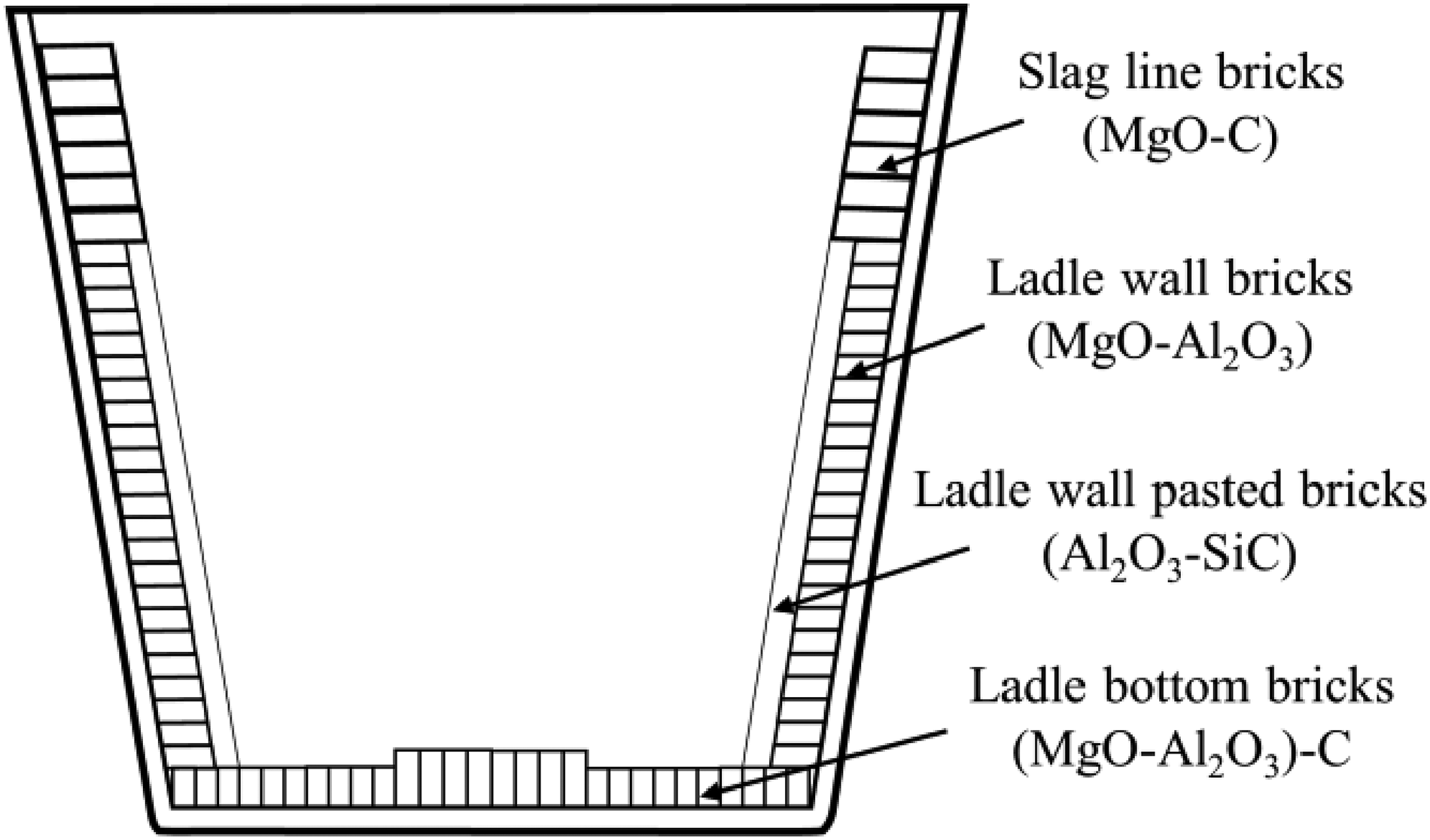
Schematic diagram for steel ladle masonry structure.
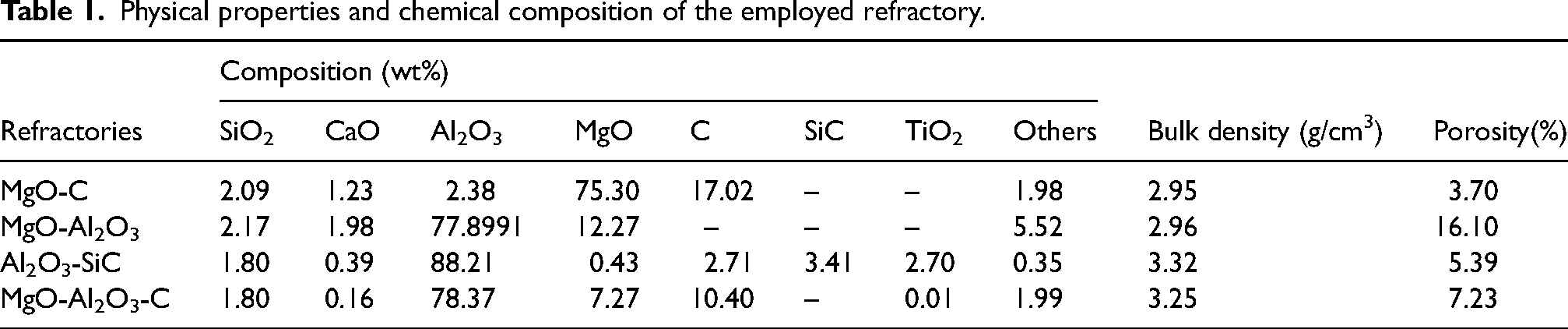
Table 1 provides the composition content and physical properties of refractory materials, and their respective phase composition results are presented in Figure 2. The data in Table 1 show that the main composition of refractories accounts for more than 90% and contains only a small quantity of impurities. XRD phase analysis results also confirm this, as other phases do not significantly exist in the four different types of refractories, except for the main phases of MgO, Al2O3, graphite or SiC.
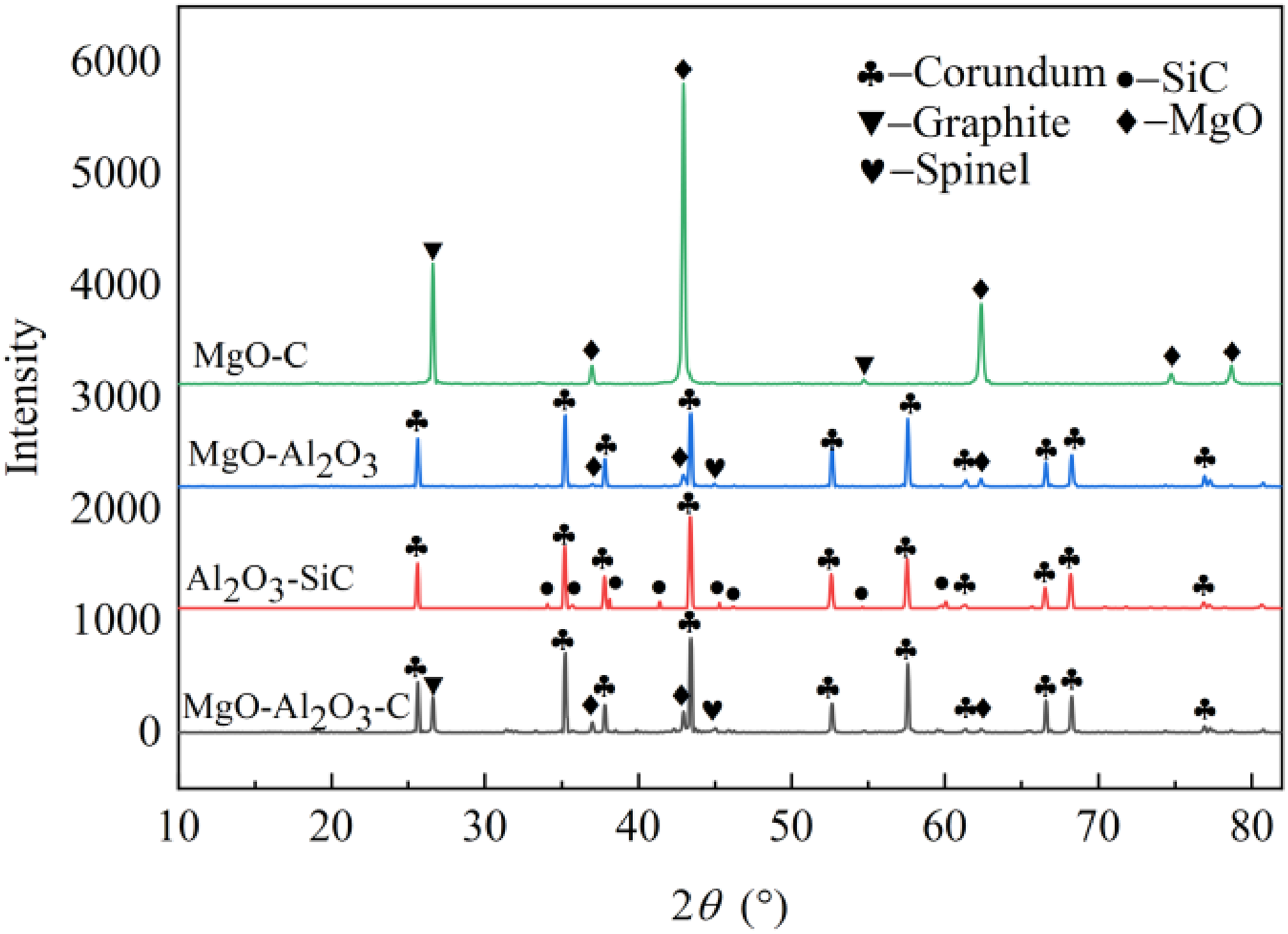
Mineralogical phases in different refractory observed by XRD.
Physical properties and chemical composition of the employed refractory.
Experimental process
The brick was cut into square bars measuring 10 mm × 10 mm × 100 mm. It was then subjected to drying treatment in a drying oven at (393 ± 5) K for more than 12 h to ensure dryness. This was taken to avoid any water adsorption by the refractory that could affect experimental results. The steel composition was designed as Fe-0.03C-0.01Si-0.2Mn-0.03Al (wt%). The raw materials used included electrolytic iron (99.995%), 75% ferrosilicon (99.95%), electrolytic manganese (99.99%), aluminium particles (99.95%), graphite powder (99.95%) and high-purity argon gas (99.999%) that was introduced during the experiment.
The experiment employed a Si-Mo resistance furnace, and the setup is depicted in Figure 3. Prior to initiating the experiment, roughly 300 g of pre-configured metal was loaded into an alumina crucible and placed in a graphite crucible. The crucible, along with the metal materials, was then set in the corundum tube's constant temperature zone.
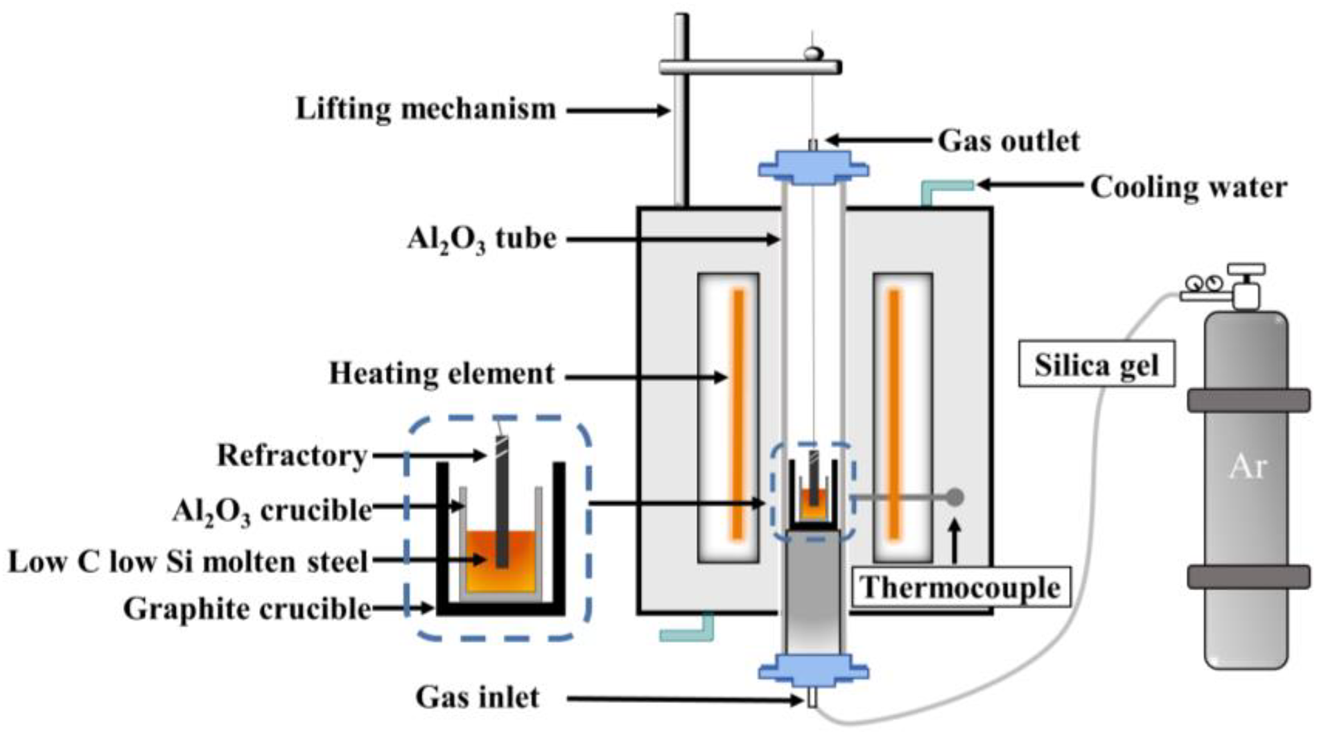
Schematic diagram of the furnace.
To ensure an optimal atmosphere in the furnace, and reduce the oxygen content in the reaction tube, high-purity argon flowed into the furnace at a rate of 4 L/min for 30 min before the experiment. The flow rate of the gas was adjusted to 3 L/min, during the melting and reaction processes. Before immersion into the molten steel, the refractory rod and molybdenum wire were connected and suspended 10 cm above the steel. The furnace was then heated at a rate of 5 K/min until the temperature reached 1873 K. At 1873 K, the temperature was held for 10 min to ensure that the metal material was fully melted. Aluminium particles were added and stirred into the molten steel, followed by a standing time of 10 min to simulate the deoxidation process of the Al-killed steel. The refractory rod was then immersed beneath the molten steel level to indicate the start of the reaction. After approximately 60 min of the reaction, the tube furnace lifting mechanism was used to lift the refractory rod for air cooling. Meanwhile, the molten steel was extracted using a quartz glass tube and water quenched to room temperature.
Experimental analysis
The steel samples and refractory materials were cut along the longitudinal axis (steel: φ 5 mm × 5 mm; refractory:10 mm × 10 mm × 10 mm). After sandpaper grinding and polishing, the samples were placed in alcohol and cleaned by an ultrasonic cleaning instrument. The scanning electron microscope (SEM) equipped with an energy dispersive spectrometer (EDS) (SEM-EDS, Nova NanoSEM400, FEI USA) was used to analyze the phase change of the refractory reaction interface layer.
Results and discussion
Initial microstructure of different refractories
Figure 4 shows the pre-reaction microstructure and composition of refractories used in ladles. It can be seen from Figure 4(a) that MgO-C refractory is mainly composed of MgO particles with different particle sizes, graphite and a small amount of impurities composed of MgO, CaO and SiO2. The graphite phase fills the gaps between the MgO particles of different sizes, and some large particles of MgO contain a minor quantity of impurities. Figure 4(b) shows that Al-Mg refractory is mainly composed of MgO and Al2O3 particles with different particle sizes. The dark area is MgO particles, and the bright area is the Al2O3 particle aggregation area. In addition, some spinel phases were found in the MgO-Al2O3 castable.
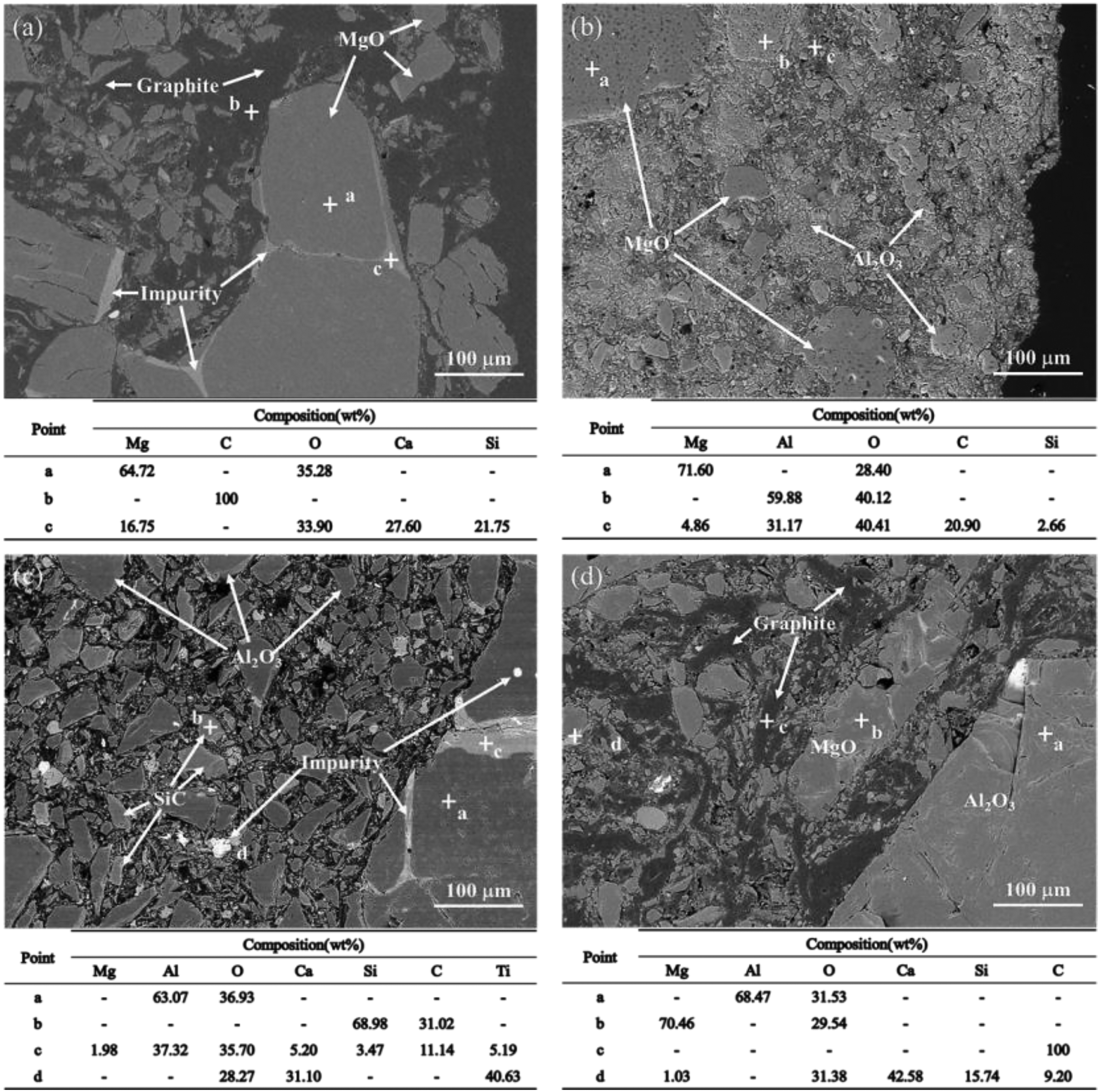
Initial microstructure and composition of different refractories used in refining ladle. (a) MgO-C; (b) MgO-Al2O3; (c) Al2O3-SiC; (d) MgO-Al2O3-C.
Figure 4(c) shows that Al2O3-SiC refractory is mainly composed of Al2O3 particles with different particle sizes and a small amount of SiC particles. There are many impurity phases in bricks, including a light gray impurity phase containing Mg-Ca-Si-Ti in large particles of Al2O3, bright white Fe particles, CaTiO2, metallic aluminium and a small amount of MgO particles. Figure 4(d) shows that the structure of MgO-Al2O3-C brick is similar to that of MgO-C brick. The structure is mainly composed of Al2O3 particles, MgO, graphite and a small amount of impurities with different particle sizes. The graphite phase fills the gaps between oxide particles of different sizes.
Interface structure
MgO-C refractory
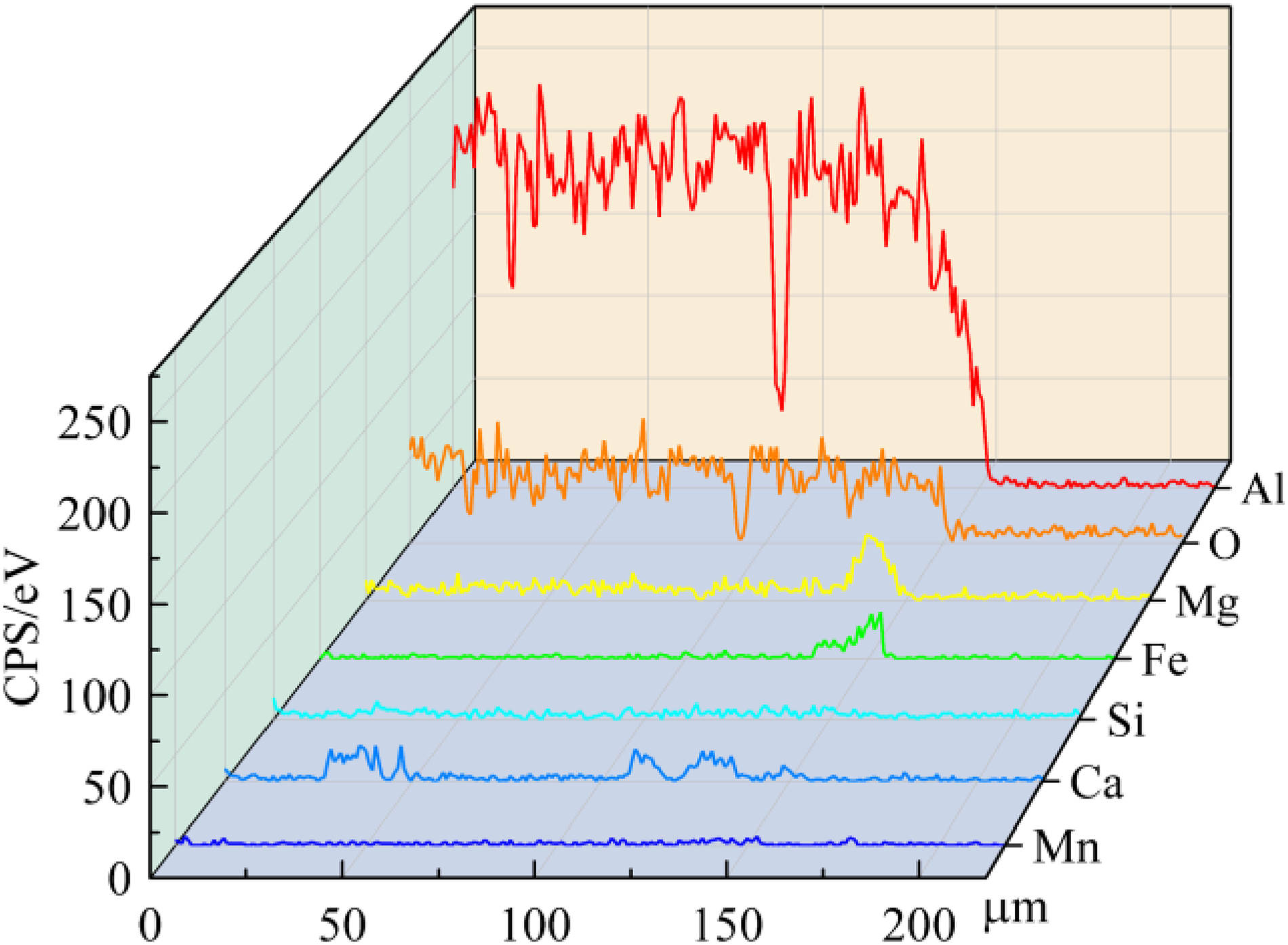
Figure 5 presents the microstructure of MgO-C refractory after 60 min of reaction with the molten steel. The surface scanning indicates the formation of a dense MgO layer at the interface. The eroded layer averages 69 μm in thickness. A low melting point compound (Ca3.6MgSi2O7.5) is generated in the CaO-SiO2 impurity phase of large particle MgO at 1873 K, which shrinks inward and causes channels to form on the surface of the refractory. This phenomenon is shown in the yellow line segment within Figure 5. Nonetheless, the MgO layer formed at the interface separates the refractory material from molten steel, effectively blocking the invasion of molten steel through the gaps between MgO particles. The white arrows shown on the micro-structure diagram indicate the position and direction of linear scanning. Figure 6 displays the linear scanning results of the MgO-C refractory interface layer. It confirms that the main elements present at the MgO-C refractory interface are Mg and O, and the generated interface is MgO. The discrepancy in the outcomes of spinel interface generation observed in previous research can be attributed to the lower [Al] concentration in the steel used in this investigation compared to the studies mentioned.19,20
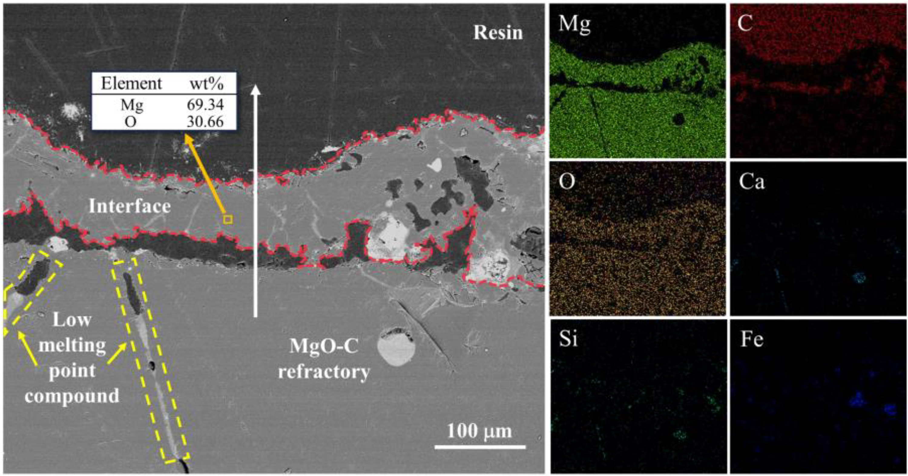
MgO-C refractory interface after reaction with molten steel for 60 min.
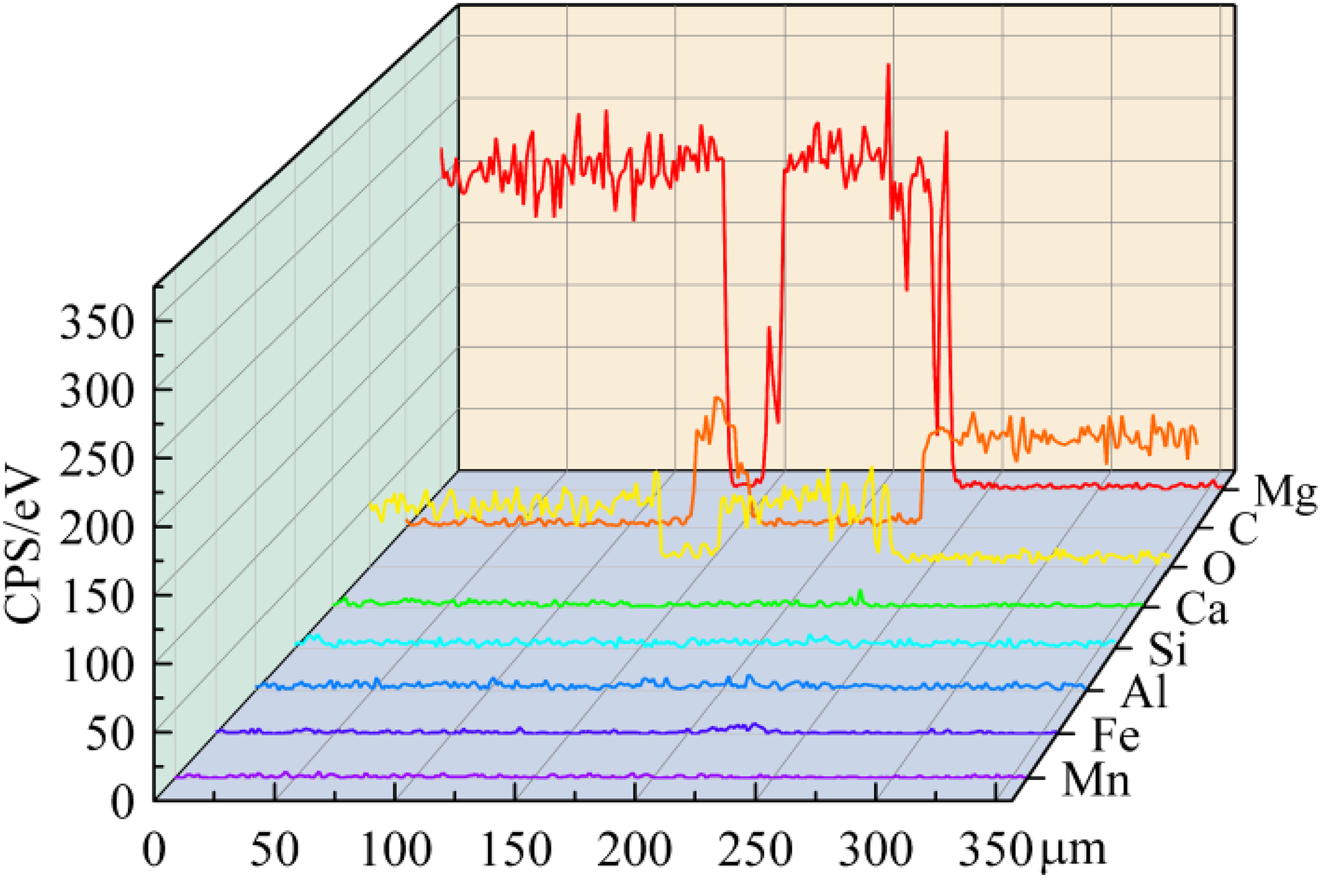
Linear scanning results of the interface between MgO-C refractory and molten steel.
The MgO-C refractory matrix is graphite phase and fine MgO powder, and the aggregate is large-diameter MgO particles, which are surrounded by the graphite phase. At the temperature of steelmaking, the graphite and MgO particles within MgO-C refractory are not stable and can be decomposed to generate Mg(g) and CO,20–22 as shown in Equation (1). As carbon present at the interface dissolves into the molten steel, the surface consistently becomes invaded by molten steel. Consequently, Mg(g) enclosed inside the refractory cannot be sufficiently released via the pores. When [O] present in the molten steel reacts with Mg(g), it converts into MgO particles as depicted in Equation (2).
23
As the magnesium oxide particles form, they increase in size and eventually merge together, resulting in the formation of a compact MgO layer.

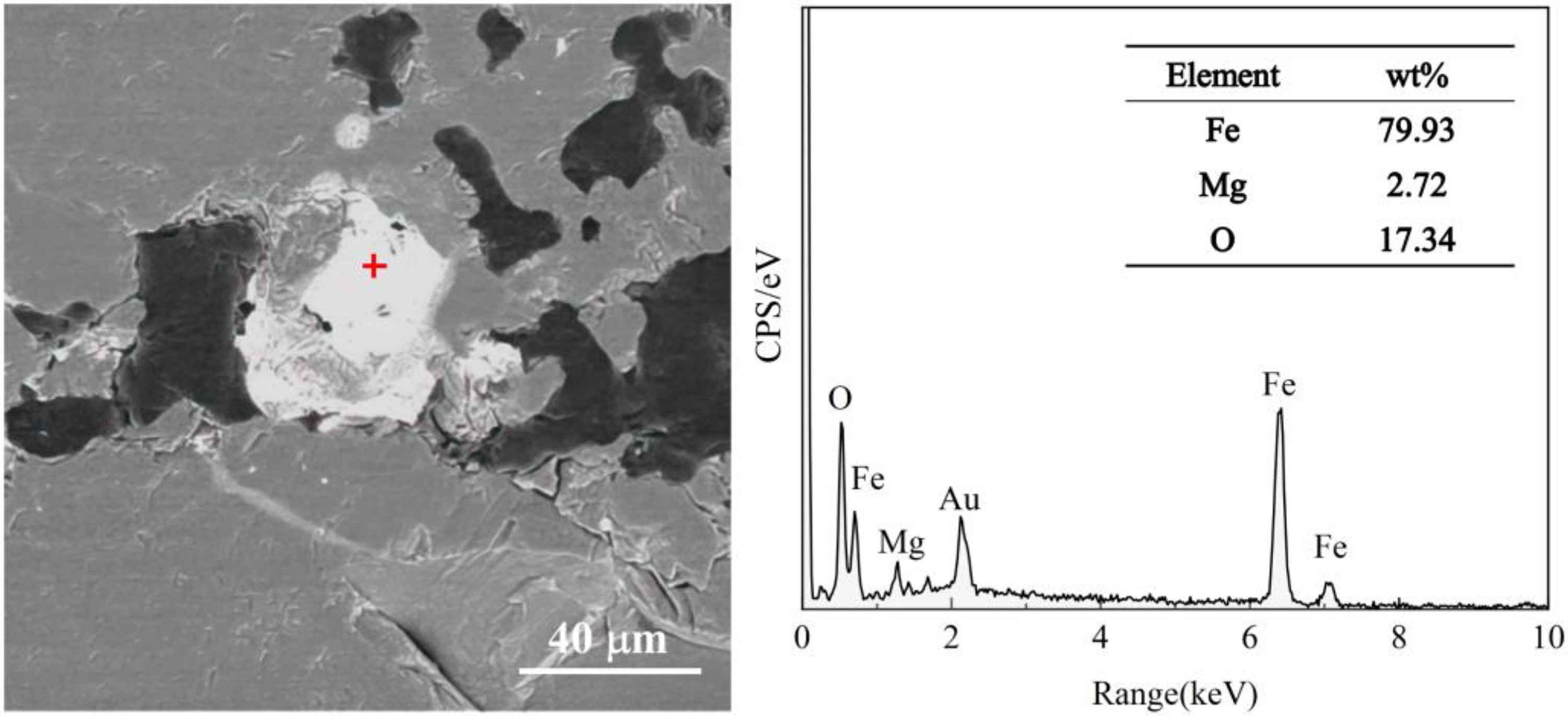
SEM image of the reaction between the molten steel and MgO aggregate.
MgO-Al2O3 refractory
The microstructure and the element mapping of MgO-Al2O3 refractory material after reacting with molten steel for 60 min are presented in Figure 8. Figure 8 reveals multiple silver-white areas within and at the interface of refractory material. These areas are the result of steady penetration and corrosion of the molten steel along the aggregate edge's loose area to the inside of the refractory material. A composite spinel layer of (Mg, Fe)Al2O4, around 20 μm in thickness, is formed at the material's interface. The linear scanning outcomes for the MgO-Al2O3 refractory interface layer are visible in Figure 9. It can be seen from Figure 9 that the interface has a higher concentration of Mg and Fe elements. The Fe gradient is apparent along the interface and gets weaker as the scan distance increases. The strength of Fe elements decreases the closer they are to the interior of the refractory. This aligns with the findings of Cheng et al. 17 The absence of the CA6 layer in this work can be attributed to the no slag added to the crucible.

MgO-Al2O3 refractory interface after reaction with molten steel for 60 min.
Linear scanning results of the interface between MgO-Al2O3 refractory and molten steel.
Figure 8 demonstrates that the reaction of Equation (3) occurred between MgO and Al2O3 in MgO-Al2O3 refractory at 1873 K, leading to the production of in situ spinel and its solid solution. This reaction results in a specific volume expansion,
24
which creates a loose area around the aggregate. During the reaction, molten steel continuously permeates inward along the loose area of the aggregate's edge, and FeAl2O4 spinel is formed through Equation (4). The resulting product reacts further with spinel in refractory to form (Fe, Mg)Al2O4, as shown in Figure 10.17,25

(Fe, Mg)Al2O4 formed at the MgO-Al2O3 refractory interface.
Al2O3-SiC refractory
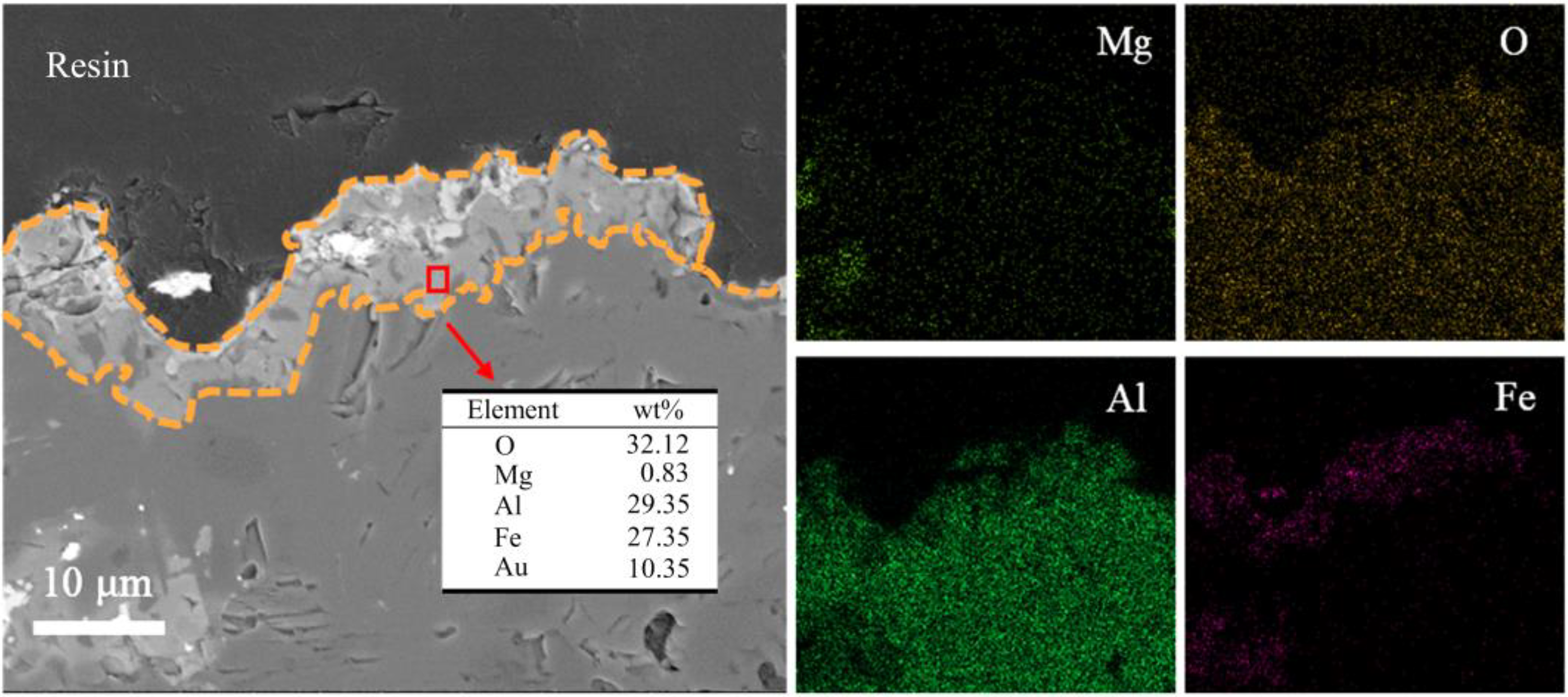
Figure 11 displays the microstructure and element mapping of Al2O3-SiC refractory after reacting with molten steel for 60 min. From the interface scan results in Figure 12, it can be observed that the Al, Si and Mg elements exist at the interface with an average thickness of approximately 65 μm. This suggests that the Al2O3-MgO solid solution phase is generated at the interface after the Al2O3-SiC refractory reacts with molten steel for 60 min. From the linear scanning results at the interface of Al2O3-SiC refractory in Figure 12, it is evident that the interface layer is enriched with Al, Mg and Si elements, while a small quantity of Fe is found in the outer area.
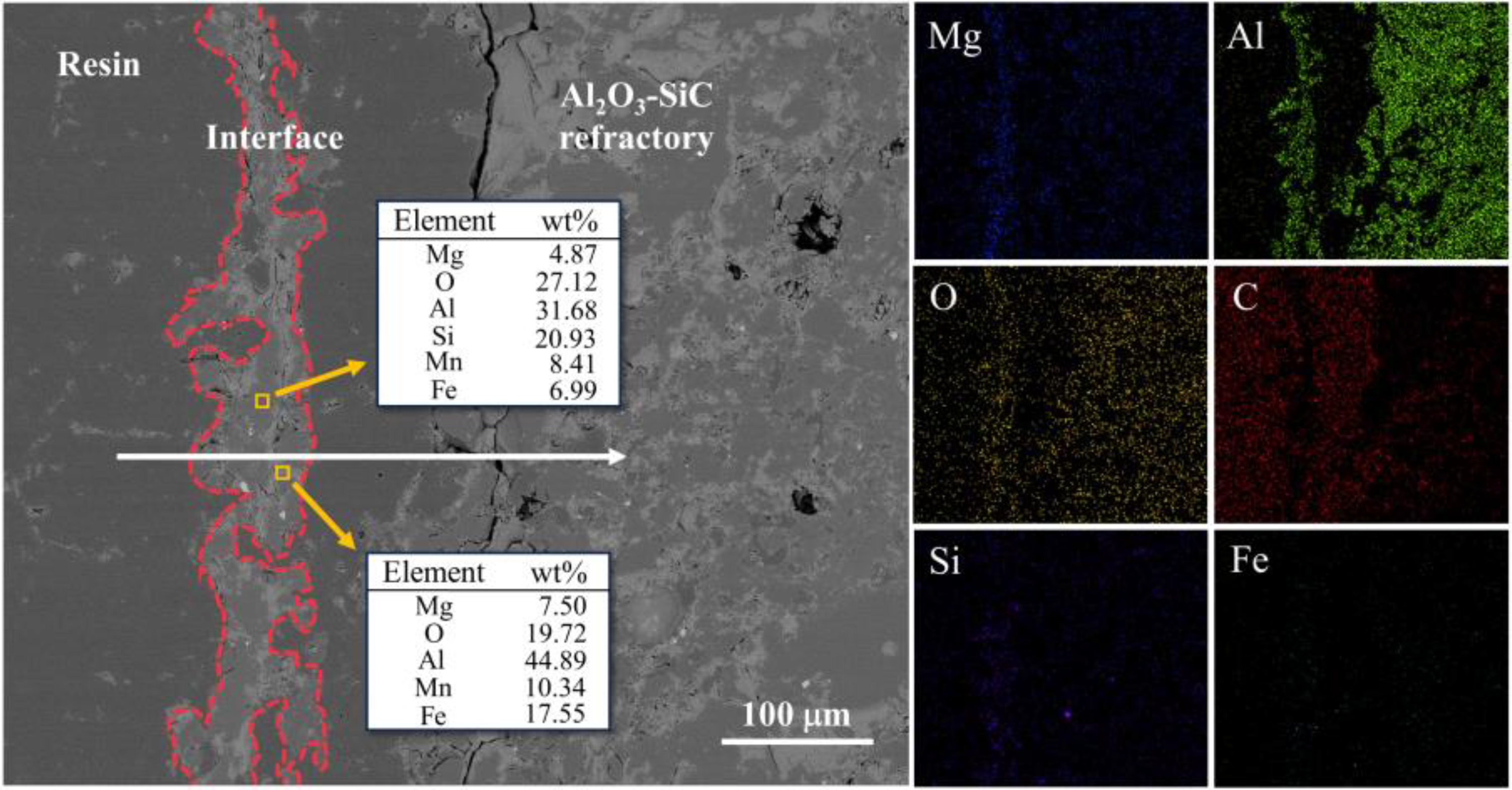
Al2O3-SiC refractory interface after reaction with molten steel for 60 min.
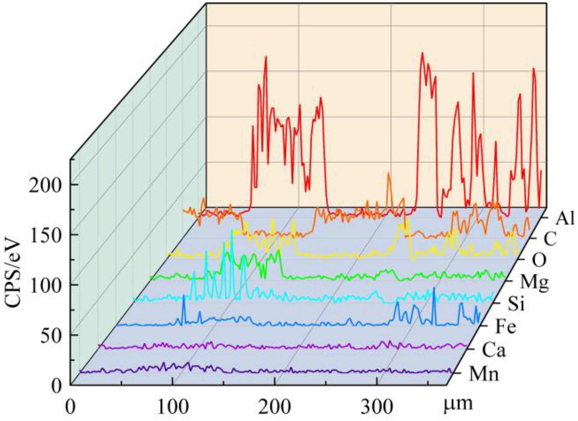
Linear scanning results of the interface between Al2O3-SiC refractory and molten steel.
The oxidation mechanism of Al4C3 to Al2O3 whisker was proposed by Hashimoto et al., 26 who suggested that Al4C3 oxidises to AlC1−xO x , resulting in the AlC1−xO x region. The authors then demonstrated that AlC1−xO x undergoes further reaction with oxygen to convert into Al2O3.27,28 Moreover, Wei et al. 29 concluded from simulations using ThermoCalc software that the formation of Al4O4C and Al4C3 is possible for the Al2O3-C system when PO2 is less than 1 × 10⁻²⁰ bar. Within the carbon-containing system, carbon significantly decreases the partial pressure of oxygen within the refractory material, enhance the formation of Al-containing gas, solid phase Al4C3 and Al4O4C. During the cooling process, these species react with oxygen to form Al2O3 and C. Unlike Wei's research, the presence of MgO was discovered at the interface. 29
The interface containing MgO is likely the result of the combined action of SiC and MgO impurities in refractory. As reported by Li et al.,
30
by consuming CO, SiC produces SiO(g), which shifts the equilibrium of the reaction in Equation (1) to the right and encourages the reduction of MgO, as shown in Equation (5). The Mg enrichment at the interface is due to the reaction of impurities in refractory containing MgO with C to form Mg(g), which diffuses and escapes to the interface of refractory material and molten steel. Furthermore, SiO(g) generated by Equation (5) diffuses to the interface and oxidises, as shown in Equation (6). This is the main reason for Si enrichment at the interface.

MgO-Al2O3-C refractory
Figure 13 depicts the microstructure and element mapping of MgO-Al2O3-C refractory after reacting with low Si low C Al-killed molten steel. As displayed in Figure 13, the slightly lighter layer at the interface is the Mg-Al spinel layer with an average thickness of 41 μm. Moreover, the refractory particles at the interface evidence apparent spalling and corrosion, and a certain number of refractory oxide particles will inevitably permeate into the molten steel and transform into large particle inclusions, adversely influencing the quality of molten steel. The refractory linear scanning results obtained by the reaction between Al2O3-MgO-C refractory and molten steel for 60 min show that the main elements accumulated at the interface are Mg, Al and O, as shown in Figure 14.
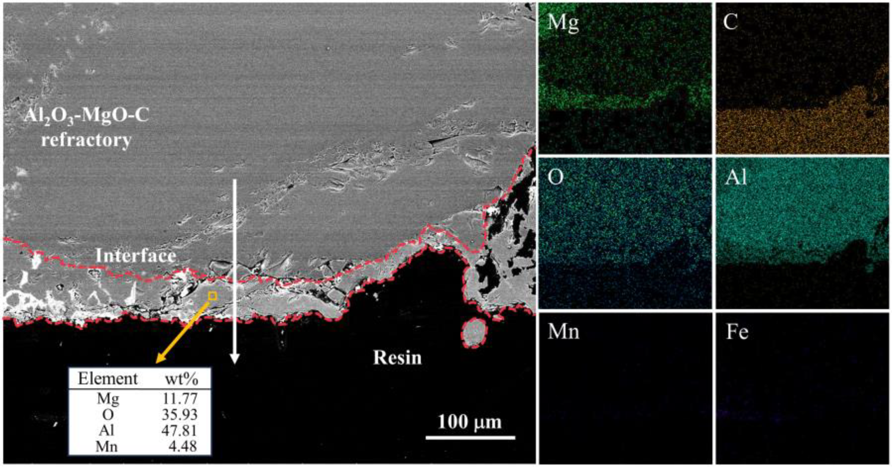
MgO-Al2O3-C refractory interface after reaction with molten steel for 60 min.
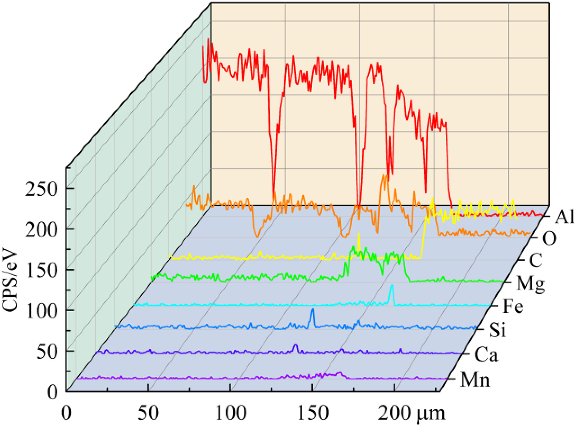
Linear scanning results of the interface between MgO-Al2O3-C refractory and molten steel.
MgO-Al2O3-C refractory is composed of graphite phase and fine powders of Al2O3 and MgO. The aggregates are large-diameter Al2O3 particles, and the graphite phase is packed in the spaces between them. When molten steel is in contact with refractory materials, the graphite phase at the interface is directly exposed to the molten steel. This causes dissolution and decarbonisation of the graphite phase, resulting in damage and continuous penetration of molten steel. The corrosion mechanism of MgO-Al2O3-C refractory with low-carbon and low-silicon molten steel is similar to that of MgO-C bricks. In contrast to the study conducted by Zhong et al., 4 only a single layer of spinel was discovered in this study, and there was no significant gradient change of Mg at the interface. This is because the formation region of spinel is close to the interface of molten steel and does not contact MgO. The diffusion rate of Mg2+ in the reaction process is limited by solid phase diffusion, which makes it difficult for MgO inside the refractory to generate a large amount of MgO·Al2O3 spinel at the interface only through Mg2+ diffusion. Thus, the formation of MgO·Al2O3 spinel layers at the interface is due to the outward diffusion of Mg(g) produced by carbon reduction along the internal channels of refractory, which then reacts with Al2O3 aggregates.
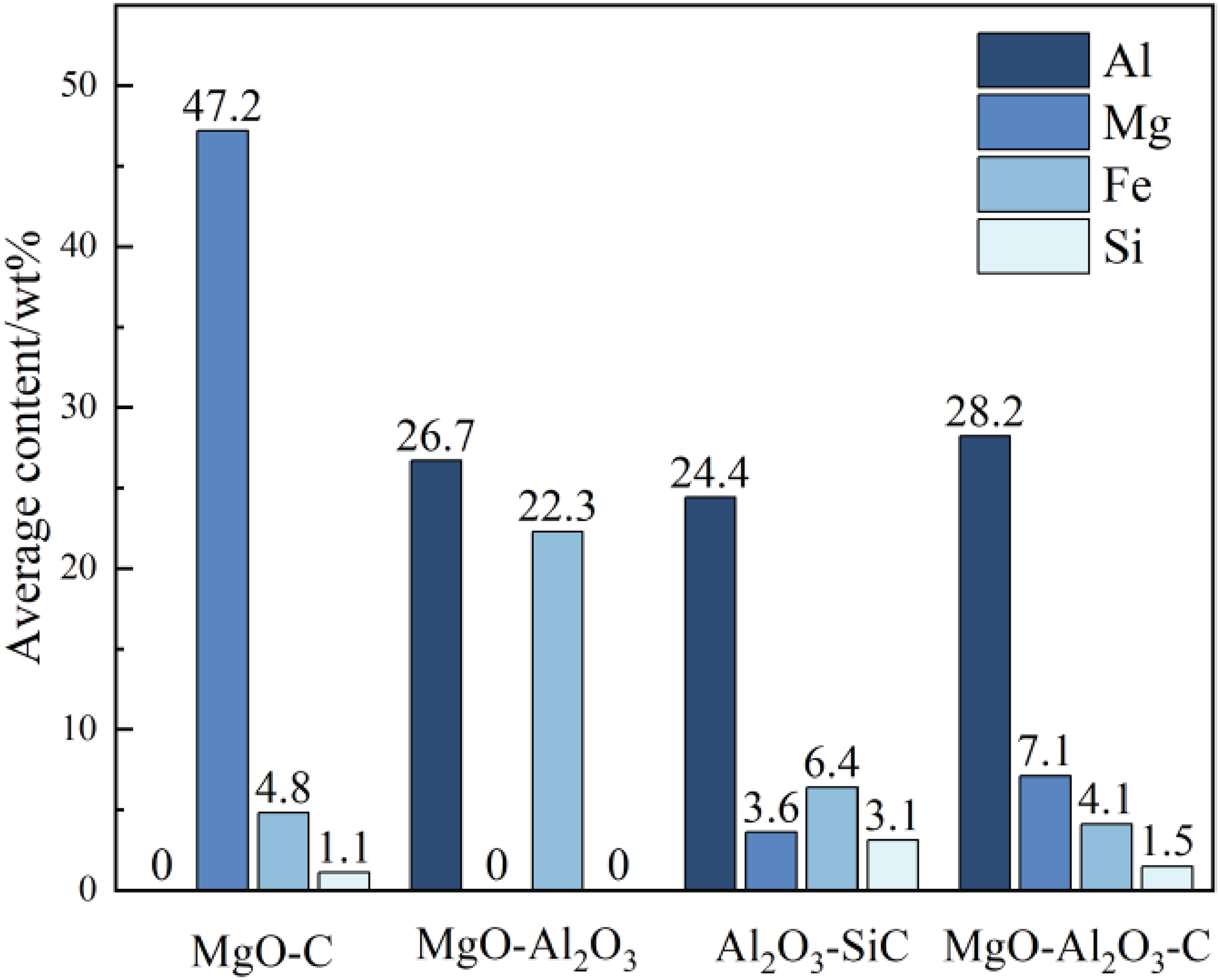
Figure 15 depicts the average proportion of elements in the reaction interface. As illustrated by Figure 15, the average content of Mg at the interface decreases in the following order: MgO-C, MgO-Al2O3-C, Al2O3-SiC and MgO-Al2O3 refractory. Mg content in the MgO-C refractory interface was significantly higher than in the other refractory materials. Meanwhile, MgO-Al2O3 refractory did not yield detectable Mg element at the interface. The peculiar outcome can be attributed to the lack of exposed MgO particles at the interface between MgO-Al2O3 refractory and MgO-Al2O3-C refractory, as well as the presence or absence of carbon. Due to the reaction between carbon and MgO, the Al2O3 on the interface of MgO-Al2O3-C refractory dissolved a little MgO. However, MgO-Al2O3 refractory did not release Mg into the interface. After quantifying the elements at the interface of MgO-Al2O3 refractory, it became evident that FeAl2.5O4 is the chief product at the interface, which affirms the main reaction between MgO-Al2O3 refractory and molten steel expressed in Equation (4). Additionally, the Si content in Al2O3-SiC refractory is 2∼3 times higher than that observed in MgO-C and MgO-Al2O3-C refractories. Since the SiO2 proportions in all four refractories were comparable, the SiC available in Al2O3-SiC refractory supplies more Si to the interface.
Average content of elements at the interface of four kinds of refractories (wt%).
Thermodynamic simulation
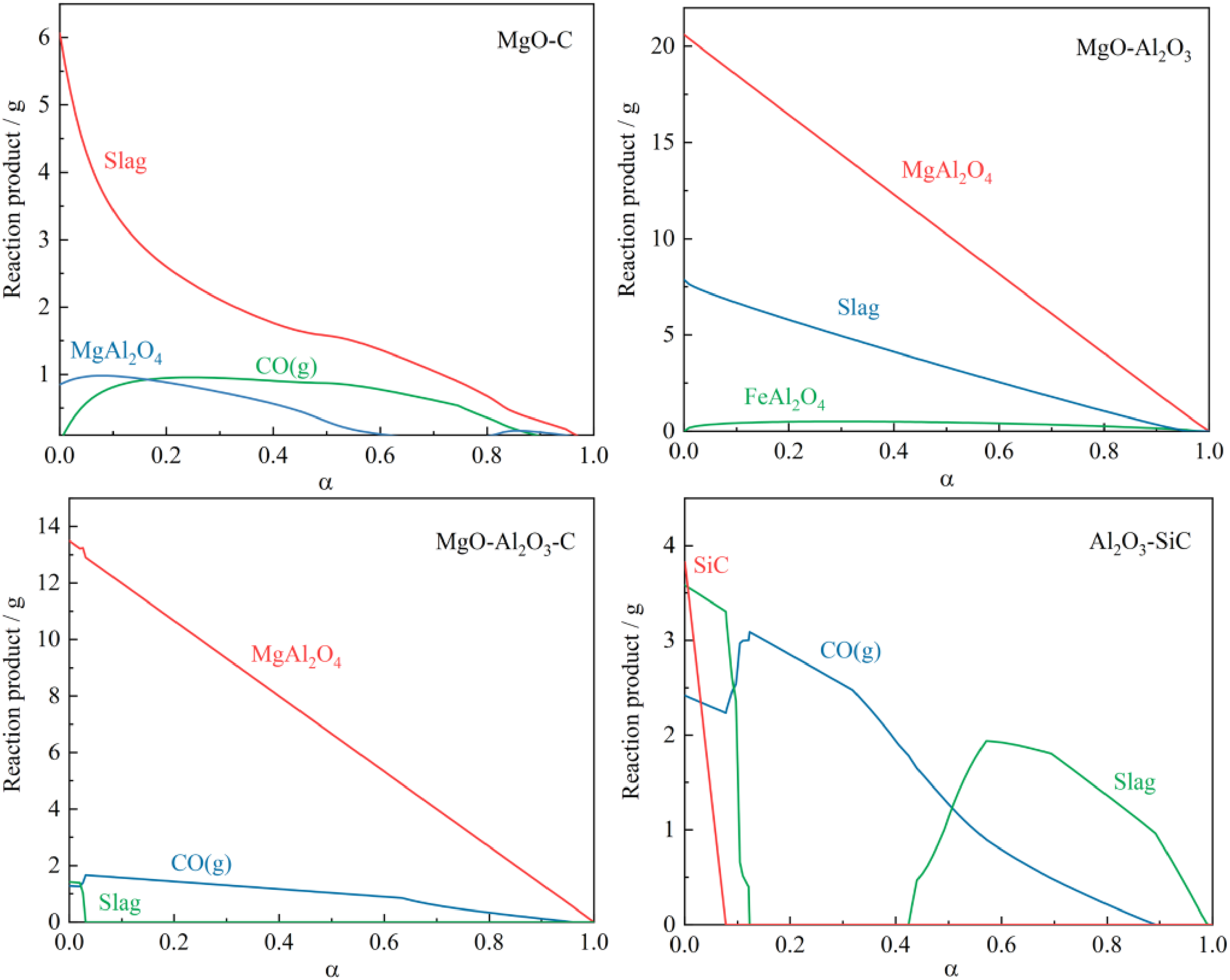
In order to better explain the corrosion process of refractory and molten steel, thermodynamic calculations of corrosion behaviour were performed using FactSage 8.1 software and databases including FactPS, FToxide, and FSstel. The coefficient of refractory material and the ratio between molten steel are defined by the parameter alpha (α = A/(A + B)), where A and B represent the fractions of molten steel and refractory, respectively, and A + B = 1. The thermodynamic calculations were conducted by combining refractory components such as MgO-C, MgO-Al2O3, Al2O3-SiC and MgO-Al2O3-C with Fe-0.03C-0.01Si-0.2Mn-0.03Al-0.003O (wt%) to analyze the phases and quantities of materials.
Figure 16 depicts the results of thermodynamic calculations of corrosion between low-carbon low-silicon Al-killed molten steel and four refractory materials at 1873 K. The outcome indicates that carbon-containing refractories create CO(g) during the corrosion calculation of molten steel. However, MgO-Al2O3 refractories do not generate CO(g), instead produce a certain amount of FeAl2O4. This is consistent with the results of SEM-EDS, as shown in Figure 10. Moreover, the SiC content in Al2O3-SiC refractory reduces rapidly with increasing proportion factor α. Once the SiC disappears, the refractory no longer performs the reaction of Equation (5), and the amount of CO(g) produced begins to increase.
Thermodynamic calculations for the corrosion of different refractories by molten steel at 1873K.
Figure 17 shows the production of Mg(g) in refractories and their impact on the [Mg] content in molten steel. It can be seen from Figure 17 that the production of Mg(g) and its effect on the average [Mg] content in molten steel are much higher when using other refractory materials. MgO-Al2O3 refractory did not produce Mg(g), which is consistent with the results of Deng.9,31 Deng et al.9,31 investigated the effect of spinel refractory on non-metallic inclusions in Al-killed steel. Since the activity of MgO in spinel refractors is minimal, producing dissolved Mg in molten steel becomes challenging. Hence, spinel refractories have little influence on non-metallic inclusions in Al-killed steel.
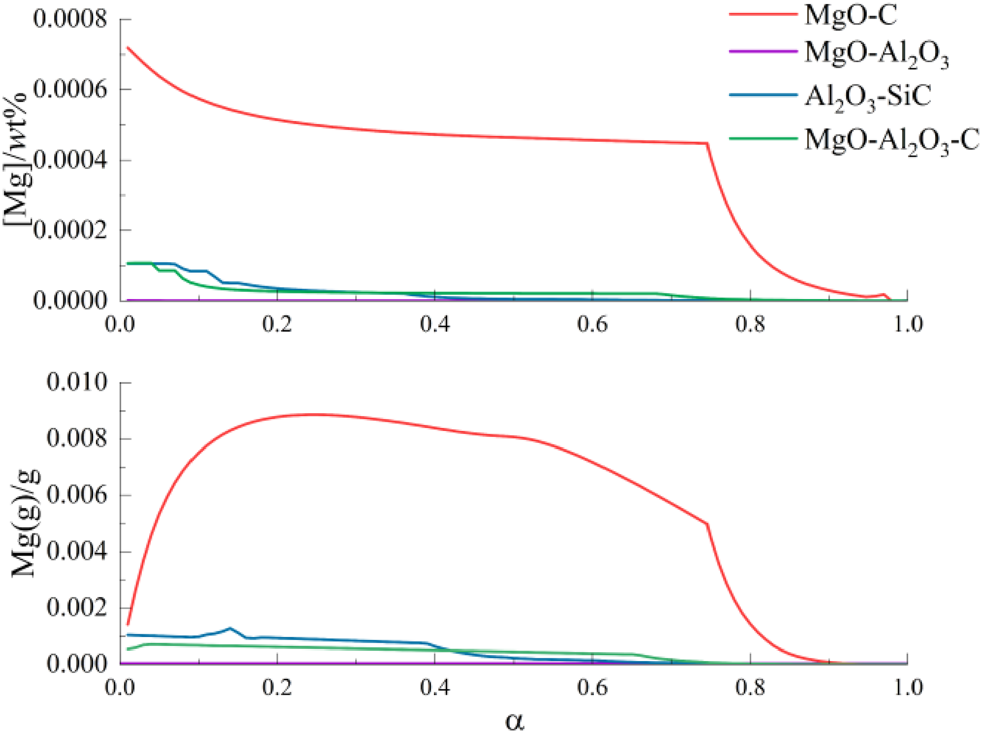
Production of Mg(g) in various refractories and their impact on the [Mg] content in molten steel.
Despite the much lower MgO content in Al2O3-SiC compared to MgO-Al2O3-C refractory, Mg(g) production is higher in Al2O3-SiC refractory due to the presence of SiC, when α<0.34. The amount of produced Mg(g) is less than 0.002 g in both of them, and their effect on the [Mg] content in molten steel is less than 0.00005 wt% after α value greater than 0.13.
In addition, the yield of Mg(g) from MgO-C refractory shows an increasing trend, followed by a decrease with an increase in the value of α. This is similar to the trend of CO(g) observed in MgO-C refractory in Figure 16. However, the low initial α value signifies a lower amount of molten steel. As a result, the production of Mg(g) in molten steel increases the [Mg] content, which subsequently decreases with an increase in α. Figure 15 provides support for the claims made in the text and enhances the reliability of the conclusions.
Conclusions
In this study, the reaction behaviour of low-carbon low-silicon Al-killed steel in contact with various refractory materials utilised in refining ladles was examined, leading to the following conclusions:
The contact between refractory materials and molten steel can produce an obvious interface layer. MgO-C refractory produces a dense MgO layer, MgO-Al2O3 refractory forms a (Fe, Mg)Al2O4 layer, Al2O3-SiC refractory generates Si-enriched MgAl2O4 layers and MgO-Al2O3-C refractory generates a MgAl2O4 spinel layer. The average content of Mg at the interface decreases in the following order: MgO-C, MgO-Al2O3-C, Al2O3-SiC and MgO-Al2O3 refractory, and SiC available in Al2O3-SiC refractory supplies more Si to the interface. Thermodynamic calculations reveal that MgO-C refractory has the greatest effect on the [Mg] content of molten steel in this study.
Footnotes
Declaration of conflicting interests
The authors declared no potential conflicts of interest with respect to the research, authorship, and/or publication of this article.
Funding
The authors disclosed receipt of the following financial support for the research, authorship, and/or publication of this article: This work was supported by the National Natural Science Foundation of China (grant number 52104339).