
Abstract
Control of carryover slag is essential during transfer of liquid steel from basic oxygen furnace to ladle to maintain preferred steel cleanliness. Carryover slag is oxidising in nature and its higher amount will lead to higher refractory wear rate, low alloy recovery and increased secondary steelmaking treatment time. Measuring the amount of carryover slag is essential for evaluating current tapping practices and implementing necessary precautions when needed. In the present study, a kinetic process model has been developed using FactSage macro processing code. Steel lollipop and slag samples were collected between tapping start and onset of ladle refining process for a medium carbon aluminium killed grade. Liquid steel-slag interaction, flux addition to slag, various metallic additions to steel and refractory dissolution to slag were taken into account in the model. Multiple simulations were performed with varying amounts of carryover slag and composition of steel and slag of initial samples from the ladle furnace were equated with the predicted values from FactSage kinetic model to determine the carryover slag amount. Apart from predicting the carryover slag amount, this model can be useful to understand the effect of tapping parameters on variations in liquid steel and slag chemistry during tapping.
Introduction
The primary method of producing steel is where the iron ore in the form of sinter, pellets, etc. along with fluxes are reduced through blast furnace (BF) route to produce liquid iron or hot metal. After that, hot metal is desulphurised in Kanbara reactor (KR) and further refined in basic oxygen furnace (BOF) by reducing the impurity elements such as C, Si, Mn, P, etc. through oxidation. 1 After BOF process, liquid steel from the BOF is transferred to a ladle furnace (LF) for refining and further processing. The process of transferring liquid steel from BOF to ladle is called tapping of liquid steel (see Figure 1). Subsequently, desired product chemistry is achieved through secondary steelmaking processing. However, owing to the turbulent nature, a certain quantity of primary steelmaking slag can also be entrained with the liquid steel during tapping process. Extensive research has been conducted for several years to figure out mechanisms governing the slag entrainment. Two key mechanisms mainly suggested are: vortex formation at a critical liquid steel height and generation of drain sinks at the later stages of the tapping process. 2 Vortex formation is predominantly influenced by the residual motion of the liquid steel and the design of the tap hole. In contrast, drain sinks occur when the liquid level is low and are defined by radial flows. 3 This primary steelmaking slag tapped with the liquid steel is termed as ‘carryover slag’. 4
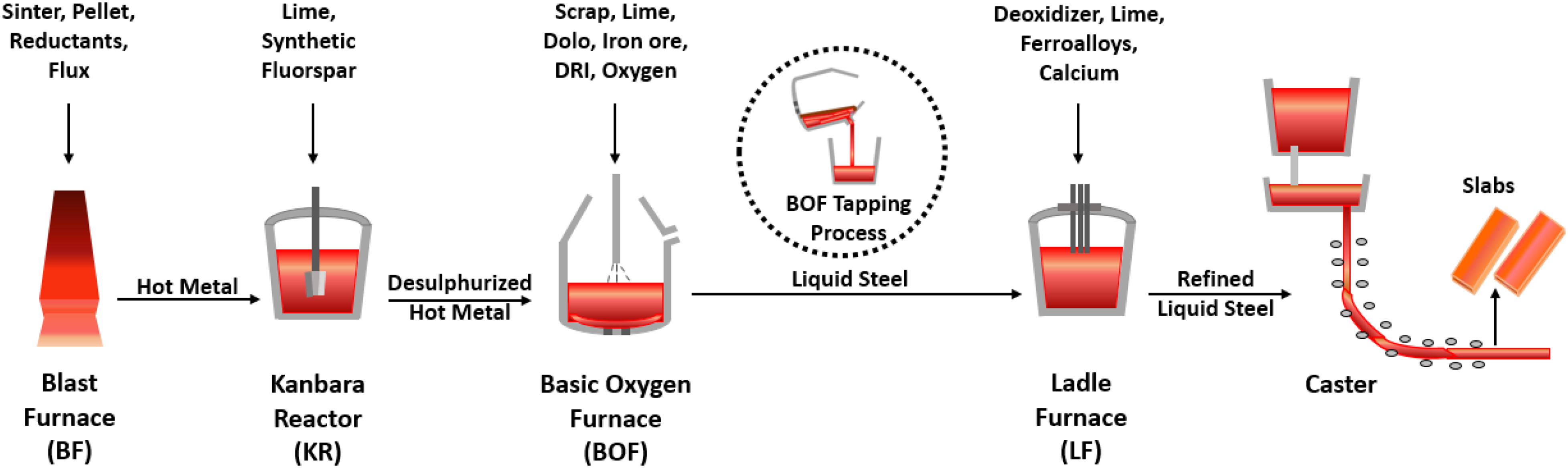
Schematic diagram of important process steps of steelmaking process.
The presence of carryover slag poses a considerable challenge due to its high oxidising potential which can have detrimental effect on alloy recovery during the secondary refining of steel in an LF. Carryover slag leads to the formation of alumina (or other oxide) inclusions in the steel as a result of the interaction between FeO and MnO in the slag with the dissolved aluminium (or other deoxidisers) in the steel. These oxide inclusions adversely impact the cleanliness of the steel. Furthermore, the carryover slag has a significant impact on the consumption of deoxidisers and the reversion of phosphorus. Higher amount of carryover slag increases consumption of aluminium as effective desulphurisation necessitates fully deoxidised steel and basic deoxidised slag having high sulphide capacity. In addition, carryover slag can cause damage to the LF lining leading to costly maintenance and repairs. 5 Therefore, it is important to control and minimise carryover slag during tapping by following proper tapping practices to ensure high-quality steel production. Usually, visual identification is a common method for detecting carryover slag in the tapping stream. 6 Some steel plants have employed alternate methods, such as electromagnetic detection systems where changes in magnetic fields are considered to detect slag. 7 Infrared detection is another non-visual reliable technique which depends on differences in emissivity between slag and steel. 8 Since the tapping rate is generally very high, it is important to interrupt flow of liquid steel as soon as slag is detected. The usual method is tilting the furnace. In contrast, Slag DART systems inject refractory material into the tap hole and it creates a barrier to restrict slag flow. Pneumatic slag stoppers can also be employed to control slag flow during tapping. Another available method is sliding gate systems where refractory components can be adjusted to block the flow of carryover slag thereby ensuring cleaner steel production. 9 Nonetheless, it is important to assess the effectiveness of these various systems by proper estimation of carryover slag amount.
Several researchers have attempted to quantify the carryover slag amount based on mass balance technique. Doostmohammadi et al. 10 and Alexis et al. 11 calculated the carryover slag amount based on CaO balance considering it to be a non-reactive oxide. Hassel et al. 12 used MgO balance for carryover slag estimation in their studies. However, thermodynamic and kinetic conditions were not considered in these methods, thereby missing the insights of chemical reactions during the tapping process. Furthermore, these methods need accurate measurement of slag weight. They have tried to quantify the carryover slag amount by suitably adding different tracers like Ba and Sr carbonate in liquid steel. However, these tracers can adversely affect the composition and morphology of inclusions and thus, these are not recommended. Consideration of phosphorus reversion is another method for the estimation of carryover slag assuming the fact that phosphorus coming to the liquid steel from slag and phosphorus impurities coming from the added ferro-alloys are properly accounted. Another challenge of this method is that kinetics of phosphorus reversion from slag to liquid steel is very slow.
Kamaraj et al. 13 developed a thermodynamic model to evaluate carryover slag amount by comparing model predicted bath silicon and experimentally measured silicon concentration of steel at the LF. FactPS, FToxid, and FSstel databases of FactSage 6.4 software package were used for the calculation. In that study, dissolved oxygen of steel was not experimentally measured, but calculated by FactSage equilibrium module. Instead of considering the addition of lime and synthetic slag during tapping, it was considered after the tapping process. Furthermore, the interaction between liquid steel and fluxes/slag was avoided after the tapping process. Total 10 steel grades having carbon concentration ranging from 0.12 wt% to 0.43 wt% were considered in that study. Authors found that the carryover slag amount can vary from 1.92 to 5.77 kg/tonne of liquid steel for these steel grades. Dali You et al. 14 worked on a kinetic process model to address the refining reactions occurred during tapping and ladle transportation stage using FactSage 7.3 software. In this study, the reaction between steel and slag at the interface was considered by effective equilibrium reaction zone (EERZ) method. In case of a 170 tonne capacity ladle and 510 kg (3 kg/tonne) carryover slag, the tapping and transportation times were 6 min and 17 min respectively. Owing to the lack of available data, the dissolution rate of slag formers, aluminium and ferro-alloys were considered as 1 kg/s, 6 Kg/s and 1.5 Kg/s respectively as per first assumptions. The adjustable parameters like overall mass transfer coefficients of steel and slag were separately calibrated based on the comparison between model predictions and experimentally measured data. Study results showed that the composition changes during the tapping process are more significant compared to those during ladle transportation.
Studies on the subject of estimation of carryover slag amount through kinetic process model based on FactSage calculation have not been well explored. In this present study, a kinetic process model has been developed using the FactSage macro processing code to estimate the carryover slag amount. While thermodynamic calculations are relatively straightforward, present study explores into the kinetic part also, taking into account the entire duration from tapping initiation to the onset of the ladle refining process. Consequently, this study allows monitoring how material additions and process parameters influence the changes in the chemical composition of liquid steel and slag. Thus, findings of this study can offer valuable insights for maintaining optimum steelmaking conditions during tapping to attain the desired chemistry of liquid steel and slag at the beginning of the ladle refining process. Further, this model can be useful for understanding the effect of carryover slag on steel quality.
Experimental procedure
A medium carbon aluminium killed steel grade heat was considered for the current study. Calcined petroleum coke (CPC) and ferro-alloy were added into the ladle during tapping to achieve the desired steel chemistry. Lime is also added to maintain a basic slag which is required to remove undesirable impurities. Furthermore, aluminium bars are added to reduce the dissolved oxygen content of liquid steel. At the end of the tapping process, ladle is taken to the argon rinsing station (ARS). The ladle has two porous plugs located at adjacent quadrant. High purging rate (around 100 Nm3/hr/plug) is normally maintained throughout this process. After that, the ladle is transported to the LF station for further processing. Steel lollipop and slag samples were collected following the completion of primary steelmaking process in BOF and at the onset of ladle refining process at LF station. Chemical composition of steel lollipop samples was measured by optical emission spectrometry analyzer. X-ray fluorescence spectroscopy analysis was used to determine the composition of slag.
Table 1 shows the different process steps followed during the entire tapping process and steel lollipop and slag sampling times with corresponding sample ID. Table 2 shows details of tapping parameters associated with the processed heat. High argon purging rate was maintained during tapping and at ARS station to enhance liquid steel-slag refining reaction. Different tapping additions (see Figure 2) were made mainly at the initial stages of tapping process. Calcined petroleum coke was added manually which contains around 98.69 wt% fixed carbon and 0.98 wt% sulphur. HCFeMn and lime were also added at the same time from bunker. HCFeMn consists of mainly around 70.74 wt% Mn, 6.37 wt% C and small amount of Si, S, and P. After these additions, aluminium bars were added manually which contains 99.79 wt% Al and up to 0.1 wt% Si.
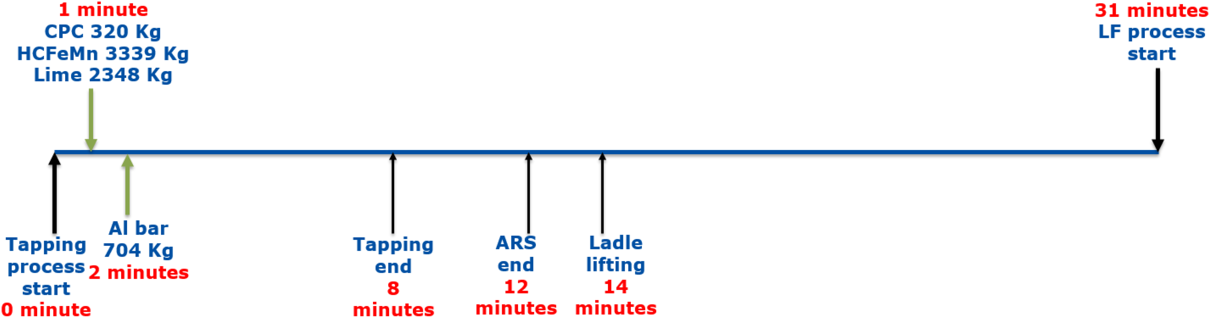
Details of slag former, CPC, ferro-alloy and deoxidiser addition during tapping process.
Steel lollipop and slag sampling times and corresponding sample ID.
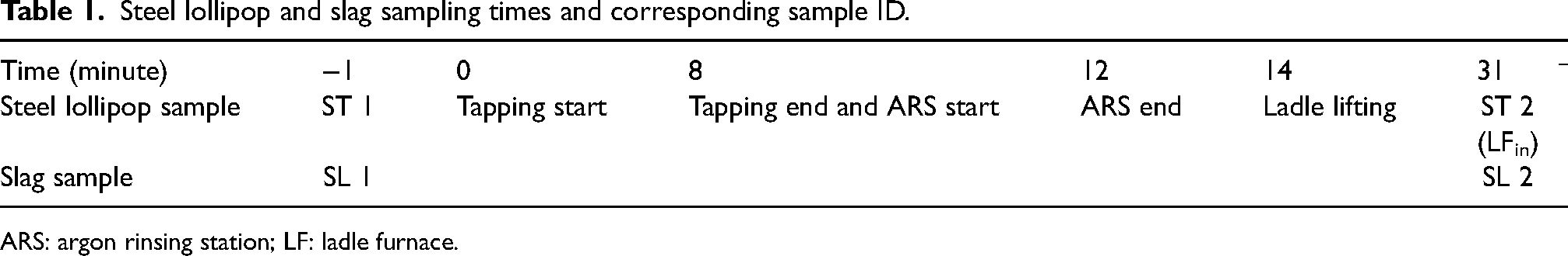
ARS: argon rinsing station; LF: ladle furnace.
Details of process parameters during tapping of liquid steel.
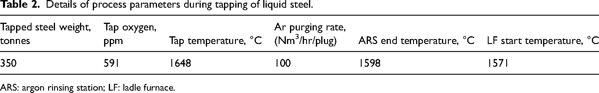
ARS: argon rinsing station; LF: ladle furnace.
Chemical composition of steel lollipop samples is shown in Table 3. ST 1 and ST 2 samples were collected just before tapping and at the onset of the ladle refining process during the trial heat. No significant change in sulphur content was observed between these periods. Phosphorous concentration remained almost constant throughout refining process. Manganese and aluminium concentration have been increased significantly due to the addition of HCFeMn and aluminium bars during the tapping process. HCFeMn and aluminium bars comprise 0.9 wt% and 0.069 wt% silicon respectively. Apart from that, silicon can revert to steel due to the reaction between aluminium present in steel and available silica in slag. Silicon concentration in liquid steel has been slightly increased after the tapping process. Table 4 shows the chemical composition of slag samples. Primary steelmaking at BOF is done in a highly oxidising atmosphere. Besides the formation of significant amount of FeO, the elements like Si, P, Mn and P get oxidised and forms highly oxidising slag. During tapping, addition of lime, aluminium bars and HCFeMn at the beginning of the tapping process form basic slag consisting of mainly CaO, Al2O3, MgO and SiO2. Some amount of carryover slag can be transferred to the LF from BOF at the end of the tapping process. However, due to the increased slag volume at the beginning of the ladle refining process, lower concentration of iron oxide (FeO) can be observed in SL 2 sample.
Chemical composition of steel lollipop samples.
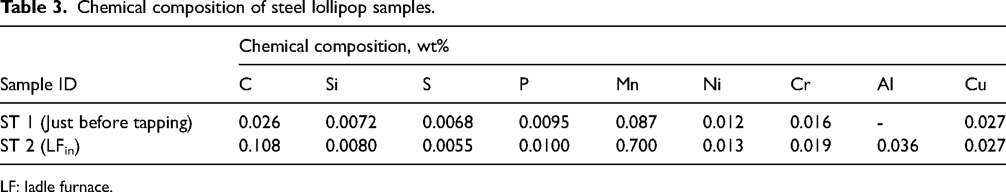
LF: ladle furnace.
Chemical composition of steel slag samples.
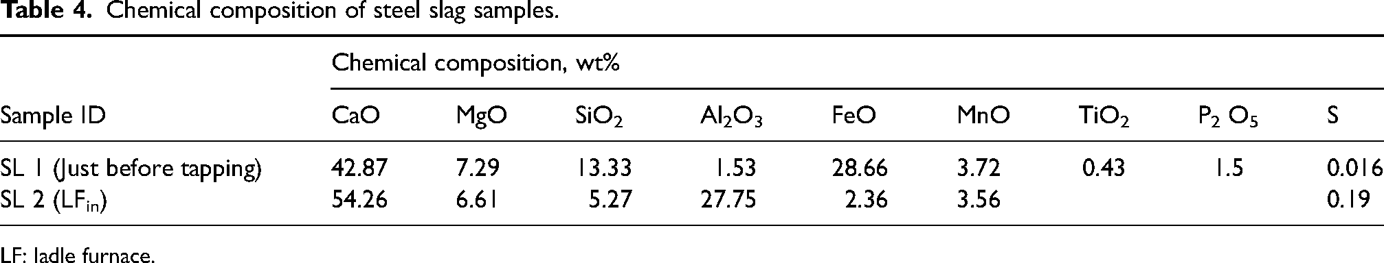
LF: ladle furnace.
Model details
Steel and slag chemistry can vary following the start of tapping process depending on process parameters and different kinds of additions. Figure 3 shows the schematic representation of calculation procedure considered in the present study. Here, the following details were considered as input parameters to start the equilibrium calculation: composition of steel and slag at BOF end process, tapped steel amount, tapping temperature and dissolved oxygen in steel just before tapping and carryover slag amount. As the carryover slag amount is unknown, therefore multiple calculations have been done considering different amount of carryover slag as input parameters. The whole process starting from tapping start to onset of ladle refining process has been divided into multiple number of time steps and FactSage calculations have been done at each time step considering a particular amount of carryover slag as input parameters. In this current study, the time step for FactSage calculation has been set as 5 s during the whole process which is also followed by Dali You et al.
14
Tapped steel amount per time step (3.64 tonne/time step) has been calculated based on the total tapped steel weight and tapping duration. At first, refining reaction at the liquid steel-slag interface was considered through EERZ approach. In the EERZ method, a complex process can be segmented into a multiple number of reaction zones where equilibrium can be calculated. This methodology functions under the assumption of uniform coefficients of all the solutes within a specific solution, such as steel/slag. In this way, the amount of each solution participating in the chemical reaction at the interface can be easily determined by equation (1).
15

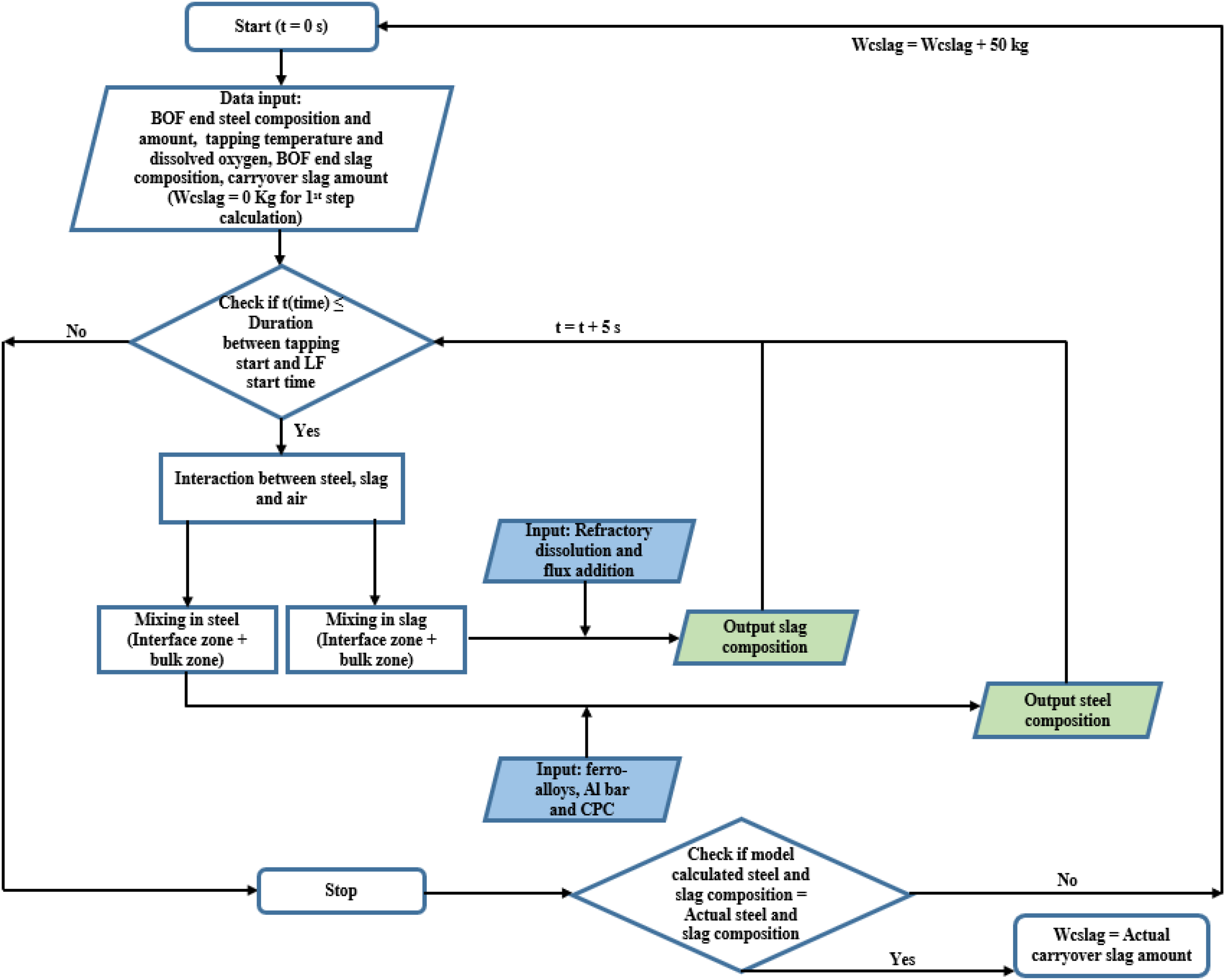
Flow chart of the steel-slag-refractory multiphase reactions modeling.
where RW, k and
Therefore, in the present study, it is assumed that the liquid steel and slag phases are separated into the interface and bulk zones. At each time step, equilibrium reaction will happen between the amount of reacting mass of liquid steel
After that, equilibrium homogenisation reactions in the steel (between bulk steel and interfacial steel zone) and slag (between bulk slag and interfacial slag zone) phase will take place. Flux addition in the slag and various metallic additions in the steel were also considered. In the present study, it has been assumed that the dissolution of lime, aluminium and HCFeMn will be continued up to the ARS end process owning to the high amount of additions and visual observation. Dissolution of CPC in steel has been assumed to be completed by the end of tapping process. Constant dissolution rate has been assumed for all type of additions. Based on the initial and final refractory thickness at the slag zone area of the ladle and total processing time, refractory dissolution rate was calculated. Constant dissolution rate of ladle refractory was assumed throughout the process. Further, it has also been assumed that the carryover slag will start to come to ladle during tapping after 85% tapped steel weight. Constant temperature drop has been assumed between the start of tapping process and the end of ARS process. Based on the tapping temperature, ARS end temperature and the process time, the calculated temperature drop per time step is 0.35 °C during this stage. Similarly, the constant temperature drop between the end of ARS process and the onset of ladle refining process has been calculated and the temperature drop value is 0.12 °C per time step. The equilibrium calculations were performed for the whole process schedule, i.e. 31 min. Multiple number of equilibrium calculations have been done considering different amount of carryover slag amount. Initially, it was started with 0 kg carryover slag amount. Subsequently, the carryover slag amount has been increased by 50 kg after each step of calculation. At the end of calculation for a particular amount of carryover slag, composition of steel and slag of initial samples from the LF were equated with the predicted values from FactSage kinetic model to determine the amount of carryover slag.
In order to calculate the amount of steel and slag to be involved in steel–slag refining reaction at the interface, overall mass transfer coefficient of steel and slag need to be determined. Stirring intensity plays a crucial role in influencing these mass transfer coefficients in an argon-stirred ladle. Accordingly, researchers have proposed various empirical relationships to calculate the stirring energy. Equation (2) mentioned by Sundberg
16
and Cicutti et al.
17
is a commonly used empirical relationship for calculating stirring energy (ε).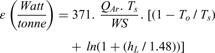
The empirical relationship mentioned in equation (3) can be used to estimate the mass transfer coefficient as a function of the stirring power.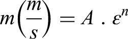
Researchers proposed different values of A and n to attain a condition which is close to the values of actual refining reaction.18,19 Cicutti et al. 17 considered the value of A as 10−5 and mentioned that the value of n can vary between 0.3 and 1.4. Van Ende et al. 15 stated the value of A and n as 0.006 and 1.4 respectively for a 165 tonnes LF. Additionally, they specified that the ratio of the overall mass transfer coefficients of slag and steel can vary between 0.1 and 0.05. Table 5 shows the important input model parameters considered for developing a kinetic process model for predicting liquid steel and slag chemistry during the tapping process. In this study, the fraction of slag (0.05) and fraction of steel (0.05) interacting at the interface during tapping of liquid steel has been assumed higher due to the high turbulence resulting from the descent of liquid steel stream and higher argon purging rate (100 Nm3/hr/plug). Subsequently, overall mass transfer coefficient of steel during ARS and ladle transportation stage has been assumed to be 0.008 m/s and 0.004 m/s respectively. Ratio of overall mass transfer coefficient of slag and steel during ARS and ladle transportation stage has been assumed to be 0.04.
Important input model parameters.
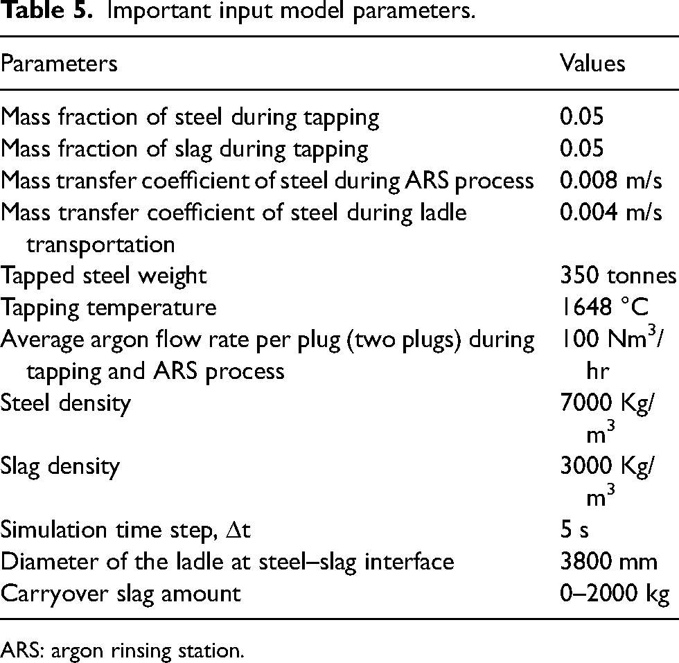
ARS: argon rinsing station.
FactSage 8.2 was used for the equilibrium calculations considering the FactPS, FToxid and FTmisc databases. Multiple equilibrium calculations were performed using FactSage macro processing code. Process schedules, composition of steel, slag, flux, deoxidiser, ferro-alloys and input model parameters were incorporated in the model by Microsoft Excel interface. Similarly, calculated steel and slag chemistry were also stored in the same Excel file.
Results and discussion
FactSage simulations have been done considering different carryover slag amount with 50 Kg calculation step size. In every computational iteration, composition of steel and slag of initial samples from the LF were equated with the predicted values from FactSage kinetic model to determine the amount of carryover slag. In this present study, simulation results along with the experimentally measured values of steel and slag composition are presented in Figures 4 and 5 respectively for 800 (2.29 kg/tonne of steel) kg, 1250 kg (3.58 kg/tonne of steel) and 1600 (4.58 kg/tonne of steel) kg carryover slag amount. It is quite evident from Figure 4 that the concentration of Al, Si, Mn and S in steel of initial LF sample is closely matching with FactSage kinetic model results calculated for 1250 kg carryover slag. When comparing the predicted data with the experimental data of the major elements, the error is within the ±5%, except for phosphorus. The model predicted concentration of P in steel for the stated three cases is somewhat higher by 40% than experimentally measured value. The composition changes during the tapping process are more significant compared to those during transportation due to the alloying and slag former additions. The addition and dissolution of aluminium bars and HCFeMn result in an increase in the concentration of Al and Mn during the tapping period. Though the Si concentration in steel decreases slightly at the starting period of the tapping process due to its interaction with ingressed air, at the end of the tapping process, Al in steel decreases to some extent due to its interaction with the carryover slag. Additionally, this interaction results in the conversion of SiO2 present in the carryover slag to Si, thereby increasing its concentration a little bit. Reversion of some amount of P from slag to liquid steel can also be observed in this period. However, subsequently, concentration of Al increases again due to the dissolution of remaining amount of aluminium. After that, concentration Al and Si continue to drop due to the formation of new oxide particles. When the addition and dissolution of HCFeMn is completed, the concentrations of Mn and P remain almost constant. Sulphur concentration slightly reduced initially due to the addition of lime and formation of basic slag. After that, it increases slightly due to the addition of new tapped steel and carryover slag at the end of the tapping process. However, after that, no significant changes observed in sulphur concentration. At the commencement of tapping, there was no carryover slag at the initial stage of tapping process. At this stage, slag mainly consists of Al2O3, SiO2 and MgO due to the dissolution of refractory and reaction of dissolved oxygen with aluminium and silicon. The total slag amount is very small (hardly few kg only) at this stage and increase in Al2O3 and SiO2 content in slag can be observed. However, after that, addition of lime results in the fast increase in the CaO content in slag. The Al2O3 content in slag increases steadily after the addition of aluminium.
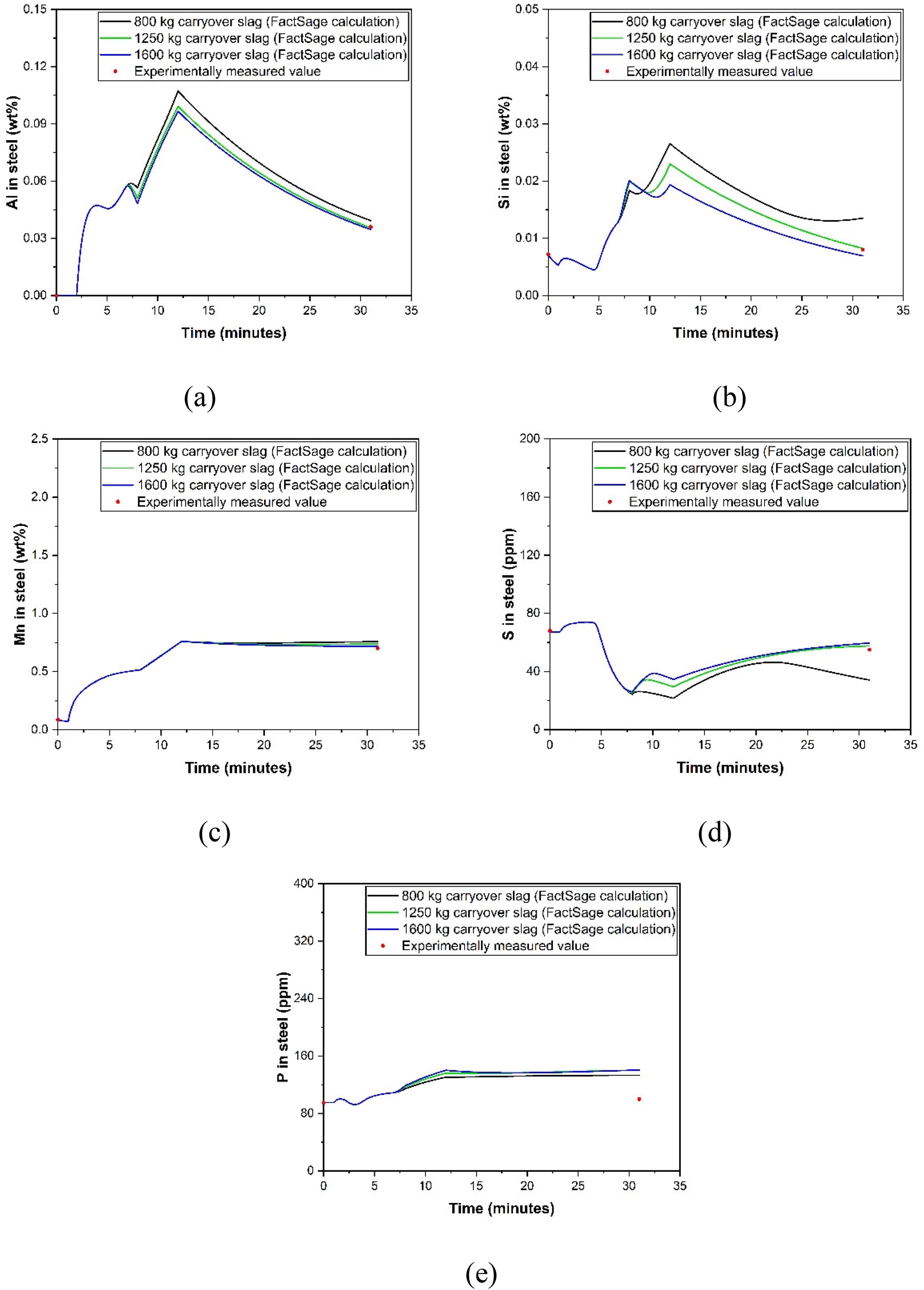
Composition profile of liquid steel from the developed FactSage model along with the experimentally measured plant data: (a) Al in steel; (b) Si in steel; (c) Mn in steel; (d) S in steel and (e) P in steel.
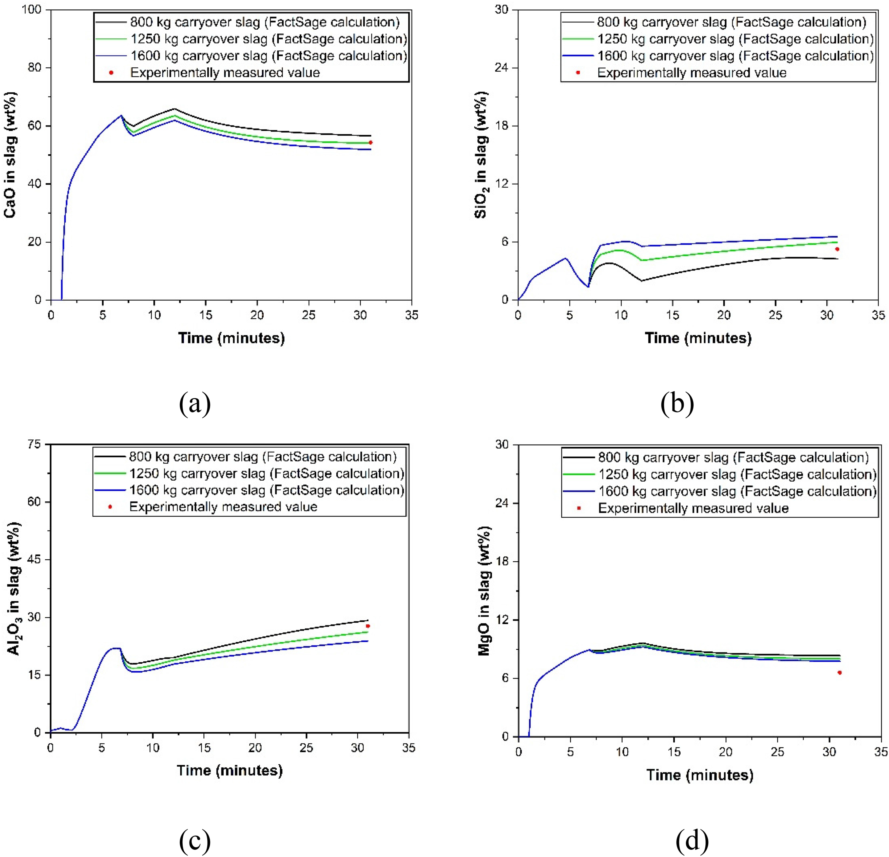
Composition profile of slag from the developed FactSage model along with the experimentally measured plant data: (a) CaO in slag; (b) SiO2 in slag; (c) Al2O3 in slag and (d) MgO in slag.
However, during the tapping end duration, addition of carryover slag leads to a slight decrease in the Al2O3 and SiO2 content due to dilution. After that, it has been increased again due to the interaction between Al and carryover slag. Subsequently, concentration of Al2O3 in slag continues to increase up to the beginning of the ladle refining process due to the formation of new Al2O3 particles. CaO concentration can be observed to decrease after the end of tapping process due to the addition of carryover slag and consequent increase in concentration of other constituent oxides of the slag. In this period, increase in SiO2 content can be observed due to addition of carryover slag and oxidation of silicon.
After the initial period of time, MgO concentration remains almost unchanged throughout the process. As per Figure 5, it pretty evident that the concentration of CaO, SiO2 and Al2O3 in slag of initial LF sample is nearly similar to the FactSage kinetic model results calculated for 1250 kg carryover slag. Similarly, when comparing the predicted data and actual data of the slag compounds, the error percentage is within ±5%. However, model predicted MgO concentration in slag is higher by 21% for all the three cases compared to the experimentally measured value. Appropriate incorporation of flux and refractory dissolution, as well as air ingression during tapping process can minimise this deviation. Kumar et al. 20 pointed out slag sampling issues (presence of metallic iron in slag, crusty slag, etc.) also for the deviation in slag composition. In case of the trial heat mentioned, as per the aforementioned criteria and simulation results, it can be concluded that the carryover slag amount is 3.58 kg/tonne of steel. Figure 6 shows that the total amount of slag generated increases with increase in carryover slag amount. Higher carryover slag amount will generate more amount of alumina due to its interaction with aluminium available in liquid steel. Figure 7 shows the effect of the carryover slag amount on FeO and MnO content in the slag. Increased carryover slag amount increases the FeO and MnO content in slag. Therefore, more amount of deoxidiser, i.e. aluminium will be consumed and aluminium concentration in liquid steel will be reduced eventually. Higher amount of FeO and MnO in slag decrease the slag viscosity and it can enhance the refractory wear rate. 21
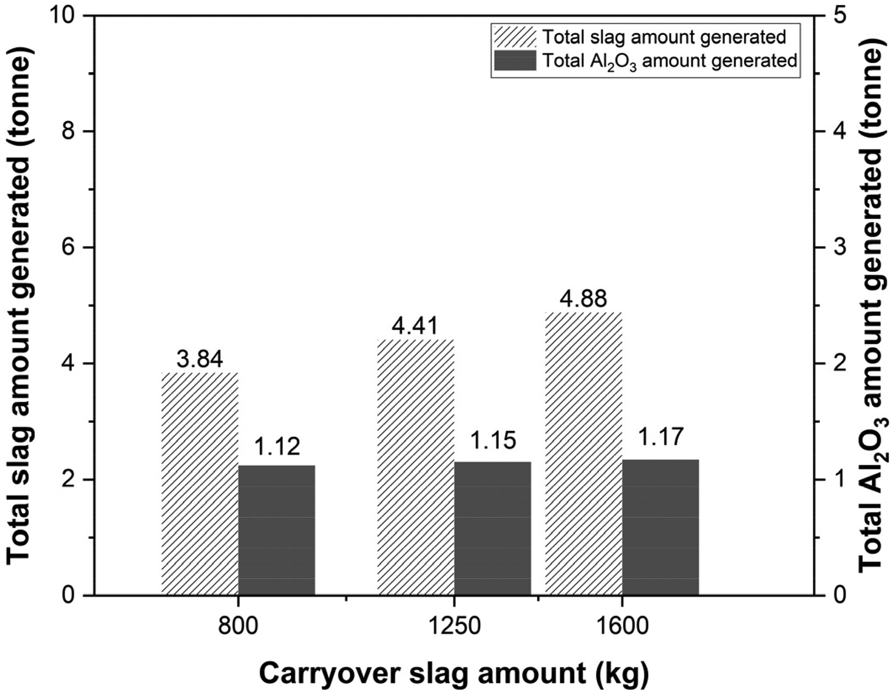
The influence of the carryover slag amount on (a) total slag amount generated; (b) total Al2O3 amount generated.
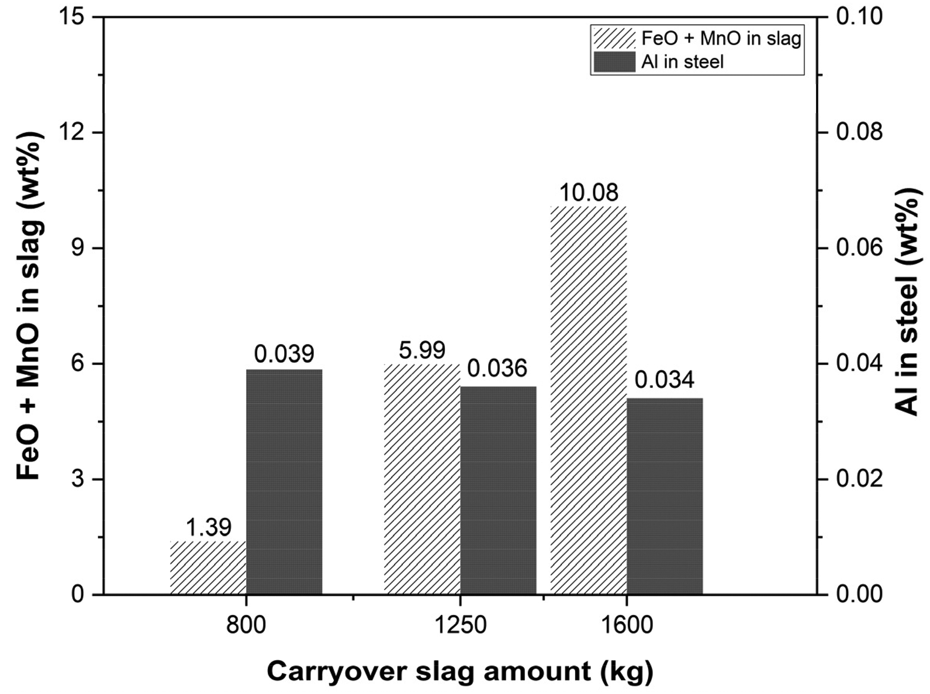
The influence of the carryover slag amount on (a) the FeO and MnO content in the liquid slag; (b) Al concentration in steel.
Conclusion
Reduced refractory life, increased process time and decreased steel quality are some of the issues that can be caused by carryover slag. It is essential to minimise the amount of carryover slag during tapping by utilising appropriate tapping practices to ensure the production of clean steel. Hence, developing a kinetic model can be a useful approach to estimate the amount of carryover slag during the tapping process. This information can assist operators in determining the optimal tapping practices to reduce carryover slag amount. Apart from predicting the carryover slag amount, the present kinetic model offers valuable insights into the chemistry of both liquid steel and slag at the onset of the ladle refining process. This insight enables steelmaking operators to make required adjustments, such as appropriate material additions and the maintenance of secondary refining parameters, if required.
The following conclusions can be made from this present study:
A kinetic process model has been developed considering using the FactSage macro processing to predict the carryover slag amount during tapping of liquid steel from BOF to LF. The study utilised the FactSage model to conduct simulations involving varying amounts of carryover slag. The composition of steel and slag in initial LF samples was compared with the predicted values from the FactSage kinetic model. In a specific trial heat, the analysis revealed that the amount of carryover slag is 3.58 kg per tonne of steel. This model can be utilised to monitor changes in both the steel and slag composition throughout the tapping process. The composition of steel and slag undergoes more substantial changes during the tapping process compared to the ladle transportation stage, primarily due to alloying and slag former additions. When comparing the model calculated data with the experimental values for major elements in steel, the error typically remains within the range of ±5%, except for phosphorus. In case of slag, model predicted MgO concentration is moderately higher compared to the experimentally measured value which may be attributed due to the slag sampling issues. Increasing carryover slag amounts in simulations result in higher amount of slag production and more alumina generation due to its interaction with aluminium in liquid steel.
Footnotes
Declaration of conflicting interests
The authors declared no potential conflicts of interest with respect to the research, authorship, and/or publication of this article.
Funding
The authors received no financial support for the research, authorship, and/or publication of this article.