
Abstract
Hypo-peritectic micro-alloyed steel has strong crack sensitivity, and marine 945 steel, as a kind of sub-encapsulated crystalline micro-alloyed steel, has frequent corner cracks during production, which seriously affects the production rhythm and reduces the product quality. Through the study of the morphology and composition of the matrix near the crack, the study and analysis of the high-temperature mechanical properties of the steel itself, and combined with the actual production situation, the causes of the corner cracks were clarified and the process optimisation was carried out accordingly. The results of the study show that the generation of corner cracks is due to the improper deoxidation process, uneven heat transfer inside the crystallizer and inappropriate cooling water parameters in the steelmaking process. By changing the deoxygenation method, crystallizer protective slag performance, crystallizer cooling water volume, water volume in the second cooling zone and other measures, the occurrence of billet corner cracks was effectively reduced, and the frequency of billet corner cracks was reduced from 6.3 to 2/m.
Keywords
Introduction
Micro-alloyed steel as a high-end steel materials are widely used in ships, automobiles and other fields, where the micro-alloying elements such as Nb, V, Ti and other micro-alloying elements can effectively improve the strength and toughness of steel. 1 As a kind of micro-alloyed steel, due to the carbon content of the steel in the range of the package crystal reaction, the liquid steel in the solidification process of continuous casting volume contraction, and micro-alloying elements of carbon and nitride will precipitate at the grain boundary, increase the grain boundary brittleness, resulting in the crack sensitivity of the steel is stronger, prone to transverse cracks in the corner of the problem, which not only affects the rhythm of production, reduce the proportion of hot delivery, but also cause a waste of resources. This will not only affect the production rhythm and reduce the ratio of hot delivery, but also cause waste of resources.2,3
Corner transverse crack is a common quality defect on the surface of continuous casting billet, at present, scholars at home and abroad on the formation mechanism of casting billet corner transverse crack and the factors affecting the formation of a large number of studies, but its formation mechanism is complex, many factors affecting the process is still a common problem in the production process of continuous casting.4–6 Although there are many reasons for corner transverse cracks, the current control of cast billet corner transverse cracks is mainly focused on the following four aspects:
Chemical composition control, the carbon element has a large influence on the crack sensitivity of steel grades, but it is difficult to adjust the carbon content, so the micro-alloying elements, S, P, etc. in the steel become the focus of control. Zhou et al. control the precipitation of AlN by reducing the content of Al in steel,
7
while Li et al. inhibit crack generation by controlling the content of N in steel.
8
Continuous casting process parameter control,9–13 by changing the crystallizer cooling intensity, the amount of second cooling water, liquid level fluctuation and other measures to achieve the purpose of avoiding the third brittleness interval of the steel grades in the straightening section, thus reducing crack generation. Tissue phase change control technology, the core of which lies in refining the surface organisation of the cast billet corners to achieve the purpose of controlling the transverse cracks in the corners.
14
Cai et al. achieved the purpose of grain refinement through corner controlled cooling to improve the high temperature ductility behaviour of the cast billet and reduce the occurrence of cracks.15,16 Chamfered crystallizer technology, which is mainly used to control corner transverse cracks by changing the heat transfer mode in the corner of the billet, increasing the temperature in the corner of the billet, avoiding the third brittleness zone, and achieving the purpose of the billet passing through the straightening section at high temperature.17,18 By developing a chamfered crystallizer, Zhang Hui and others made the corner temperature of slabs in the straightening section increase by 100°C, and the transverse corner cracks were reduced by 95%.
19
At present, due to the limitation of micro-alloyed steel use environment, the research on corner crack control is more focused on continuous casting slabs and less on large section continuous casting billets.
In this article, for a steel mill in the production of section of 320 mm × 410 mm marine 945 hypo-peritectic micro-alloyed steel continuous casting of large square billet prone to transverse cracks in the corners of the situation, a detailed analysis of the causes of cracks and based on this industrial optimisation experiments. By studying the ductility behaviour of this steel grade, the composition and organisation of the matrix inside and around the cracks were analysed, and the causes of cracks were clarified. By optimising the crystallizer cooling water quantity and the water quantity in the second cooling zone, the generation of cracks in the corner of the cast billet was effectively controlled, and the quality of the cast billet was improved.
Experimental section
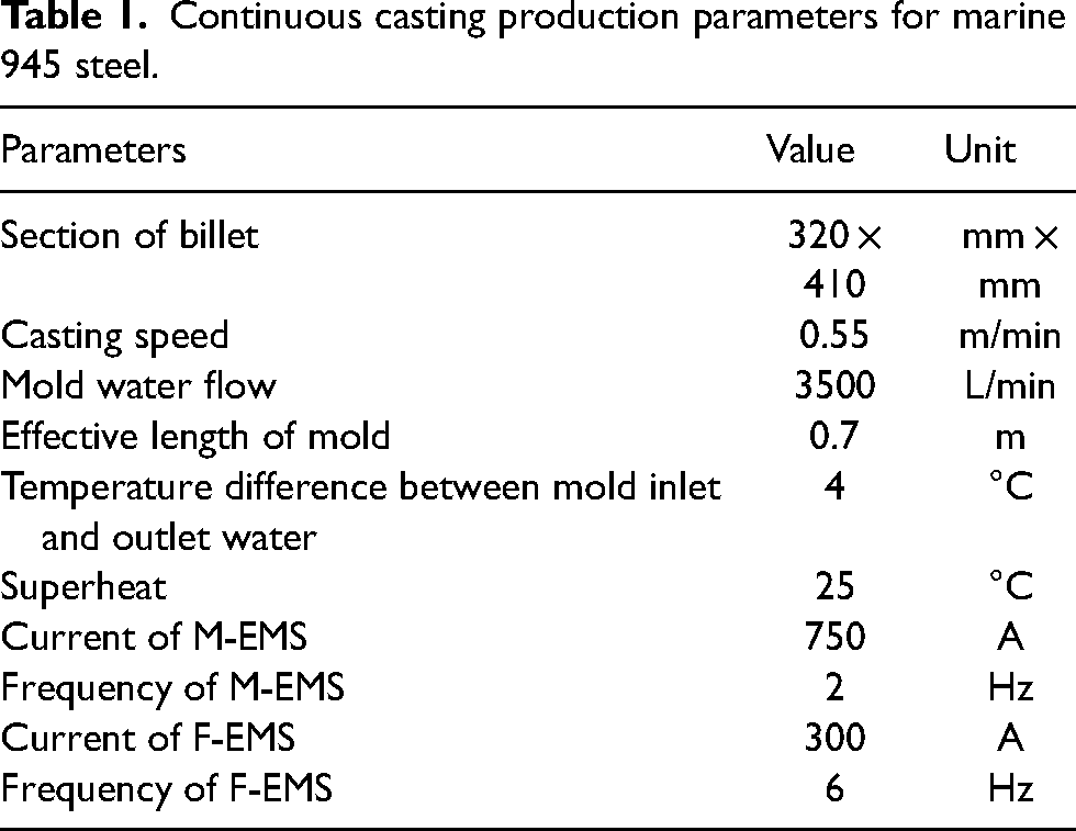
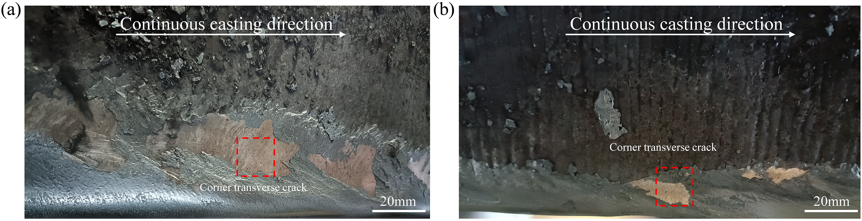
A steel plant in the production of marine 945 steel, continuous casting billet surface of the inner arc side of the existence of obvious corner transverse cracks, as shown in Figure 1(a) and (b), which collapsed the corner of the transverse crack length of about 27 mm, not across the corner of the crack length in the range of 6.5 to 25.2 mm, at the same time there is a clear depression in the surface of the casting billet, vibration marks deeper, as shown in Figure 1(c), cracks appear in the valley of the vibration marks, the casting of billet. The number of cracks in the corners was counted, and the frequency of cracks was 6.3 cracks/m. The large number of cracks and the long penetration depth led to the need for grinding of the billet, which is shown in Figure 1(d). The parameters of continuous casting during production are shown in Table 1, in which the solidification end electromagnetic stirring (F-EMS) is installed at the position of 12 m from the meniscus, and the straightening section is at the position of 15.3 to 22.6 m from the meniscus, and the chemical composition of steel grades is shown in Table 2.

Typical crack morphology (a) corner crack morphology, (b) corner crack morphology, (c) billet surface vibration marks, and (d) billet corner after grinding morphology.
Continuous casting production parameters for marine 945 steel.
Chemical composition of marine 945 steel, wt%.

In order to analyse the cause of cracks, a specimen with corner transverse cracks was cut from the continuous casting billet using a wire cutter with a size of 15 × 15 × 15 (thickness direction) mm, as shown in Figure 2 cracks penetrate to a depth of 11 mm in the thickness direction and 15 mm in the broad face direction. Which was ground and polished on a metallographic grinding and polishing machine, and the specimen was eroded using a 4% nitric acid-alcohol solution as a way of observing the metallographic microstructure in the vicinity of cracks, and the morphology and composition near cracks were analysed by using a scanning electron microscope (SEM) and an energy spectrometer (ESI). At the same time, SEM and ESI were used to analyse the morphology and composition in the vicinity of the cracks.
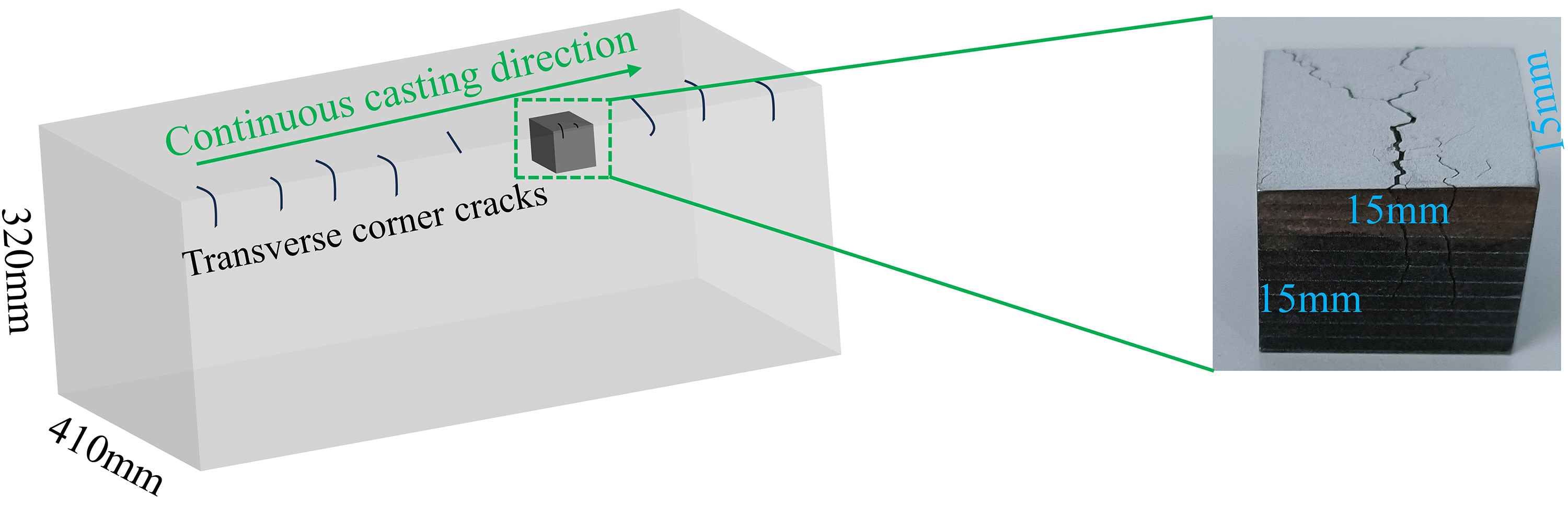
Schematic diagram of cracked specimen sampling.
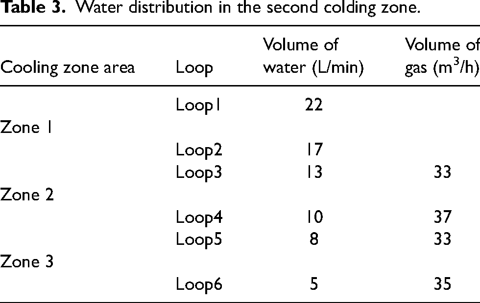
Procast software was used to simulate the change rule of temperature in the corner of the casting billet during the continuous casting process, and the solid phase line temperature and liquid phase line temperature of the steel grade were obtained through JMatPro calculation, which were 1473°C and 1508 °C, respectively, and the other physical parameters are shown in Figure 3, and the amount of water in the second cooling zone during the on-site production is shown in Table 3.
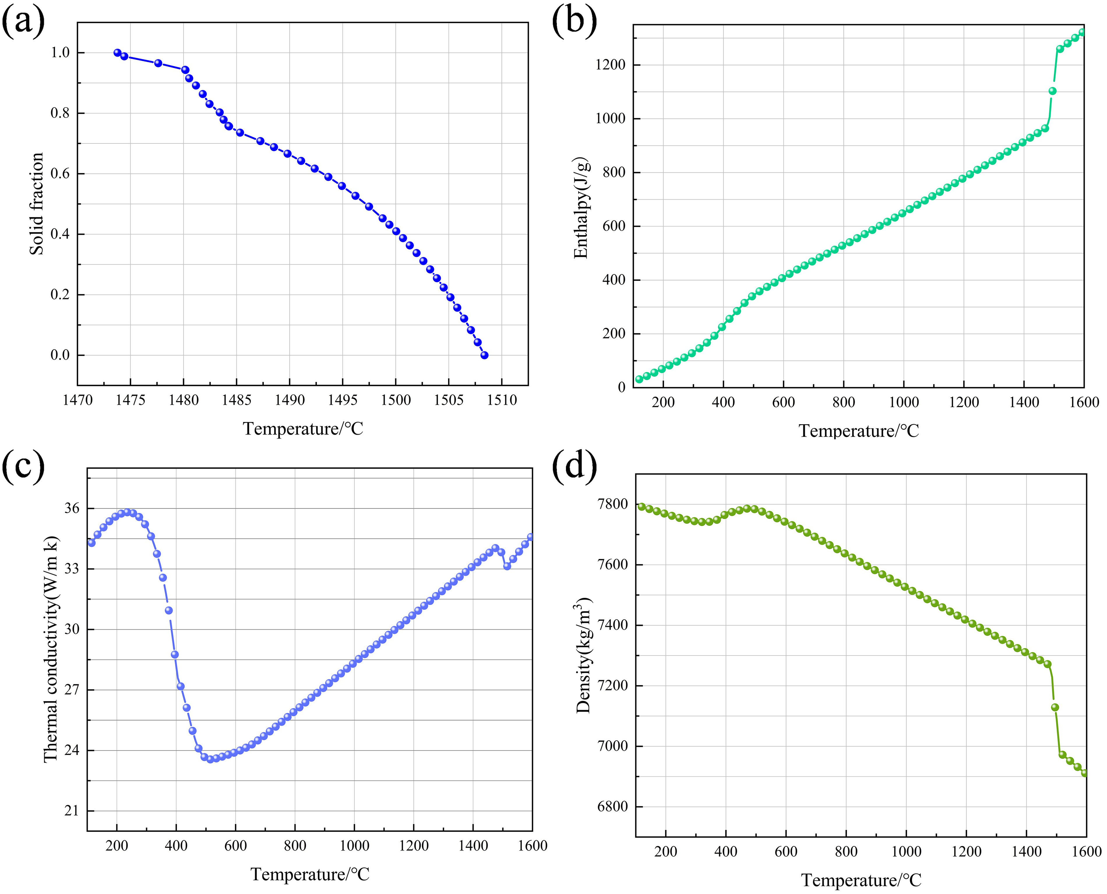
Physical parameters of marine 945 steel grades (a) solid fraction, (b) enthalpy, (c) thermal conductivity, and (d) density.
Water distribution in the second colding zone.
The ductility behaviour of marine 945 steel under different temperature conditions was determined using a Gleeble thermal simulator, and the heating regime of the specimens during the tensile experiments is shown in Figure 4. The specimens were heated to 1350°C at a heating rate of 10°C/s, held for 5 min, and then cooled down to a predetermined temperature (1200°C, 1150°C, 1100°C, 1050°C, 1000°C, 950°C, 900°C, 850°C, 800°C, 750°C and 700°C) at a cooling rate of 3°C/s, and then tensile at a strain rate of 1 × 10⁻³ until the specimen fractured, and finally the specimens were air-cooled to room temperature. The section area was calculated by measuring the section diameter of the drawn specimen several times to determine the section shrinkage of the steel grade at different temperatures.
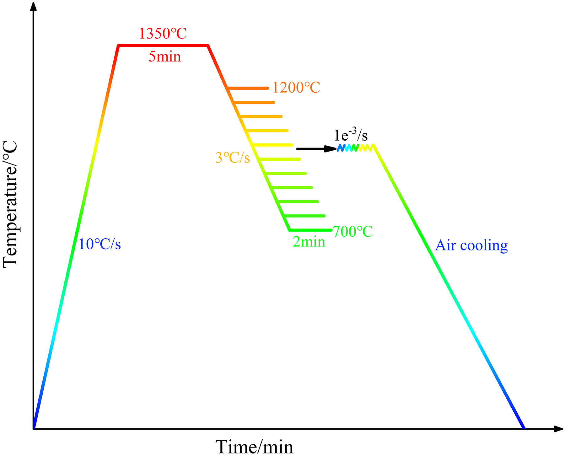
Heating regime of specimen for hot tensile test.
Results and discussion
Crack analysis
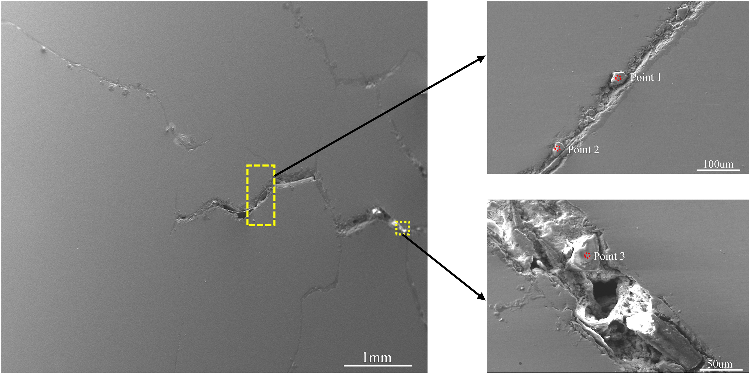
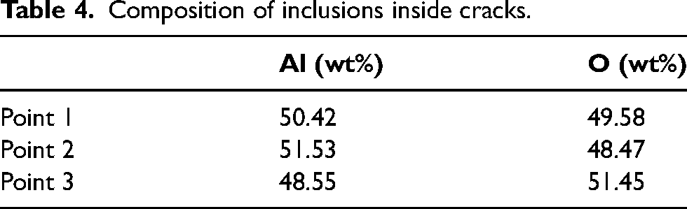
The internal morphology of the crack was observed using SEM, as shown in Figure 5, and it was found that there were inclusions inside the crack. In order to further analyse the composition of inclusions, the ESI was used to spot analyse the inside of the inclusions, and the results of the semi-quantitative compositional analysis are shown in Table 4, which indicate that there is an Al2O3 type of inclusions inside the crack, with a size between 28 and 30 um. For the source of Al2O3 inclusions in the cracks, it is thought that they may be produced in the steelmaking process, as a deoxidising product in the molten steel (Al is used for deoxidising in the steelmaking process). The Al2O3 inclusions in the cracks may also be the composition of the protective slag in the crystallizer, which enters into the cracks after the billet cracks, but elements such as Na and F are not found in the cracks, so it is thought that the inclusions are not caused by the protective slag.
Analysis of inclusions inside cracks.
Composition of inclusions inside cracks.
Using 4% HNO3 acid and alcohol solution on the cracked specimen for metallographic tissue erosion, followed by the use of metallographic microscope to observe the microstructure around the crack, the results are shown in Figure 6, the presence of obvious pre-eutectic ferrite film around the crack, pre-eutectic ferrite film at the widest place for 175.09µm.
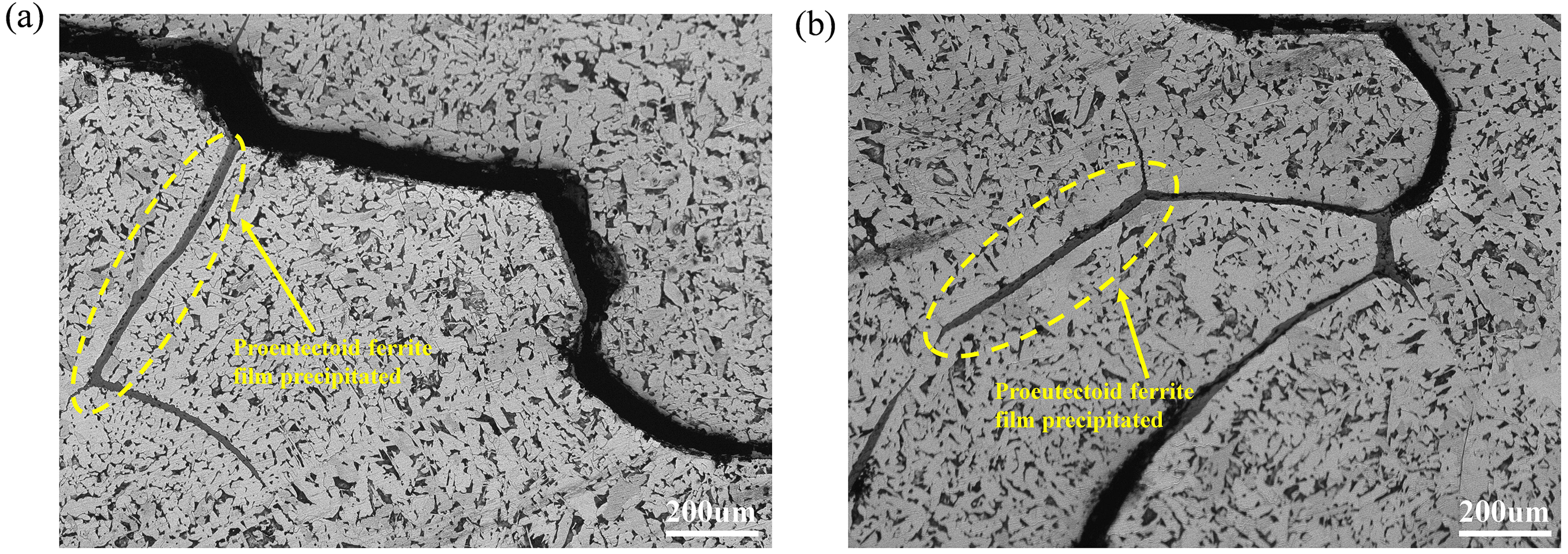
Metallographic organisation near cracks.
Thermoplastic analysis of steel grades
It is generally believed that there are three high-temperature brittleness intervals for steel grades between 600°C and the liquid-phase line temperature, and the formation of transverse cracks at the corners of the cast billet is related to the third brittleness interval of the steel grade. Combined with the actual situation, for this steel grade, the temperature interval where the section shrinkage is lower than 60% is considered as the high-temperature brittle interval. Samples were taken from the continuous casting billet for high-temperature tensile experiments, and the tensile fracture of this steel grade at different temperatures was obtained. After the specimens were pulled off, the section diameter of the pulled off specimens was measured several times as a way to calculate the section shrinkage, and the results are shown in Figure 7. The results show that the lowest section shrinkage is 36.8% at 750°C. The first and second brittleness intervals do not exist for this steel grade, and the third brittleness interval is in the range of 720°C to 890°C. Some research results show that inclusions such as MnS have a significant effect on the ductility behaviour of steel grades,20,21 and for the significant decrease in the ductility behaviour of steel grades at 1150°C, which may be caused by the presence of inclusions within the specimen.
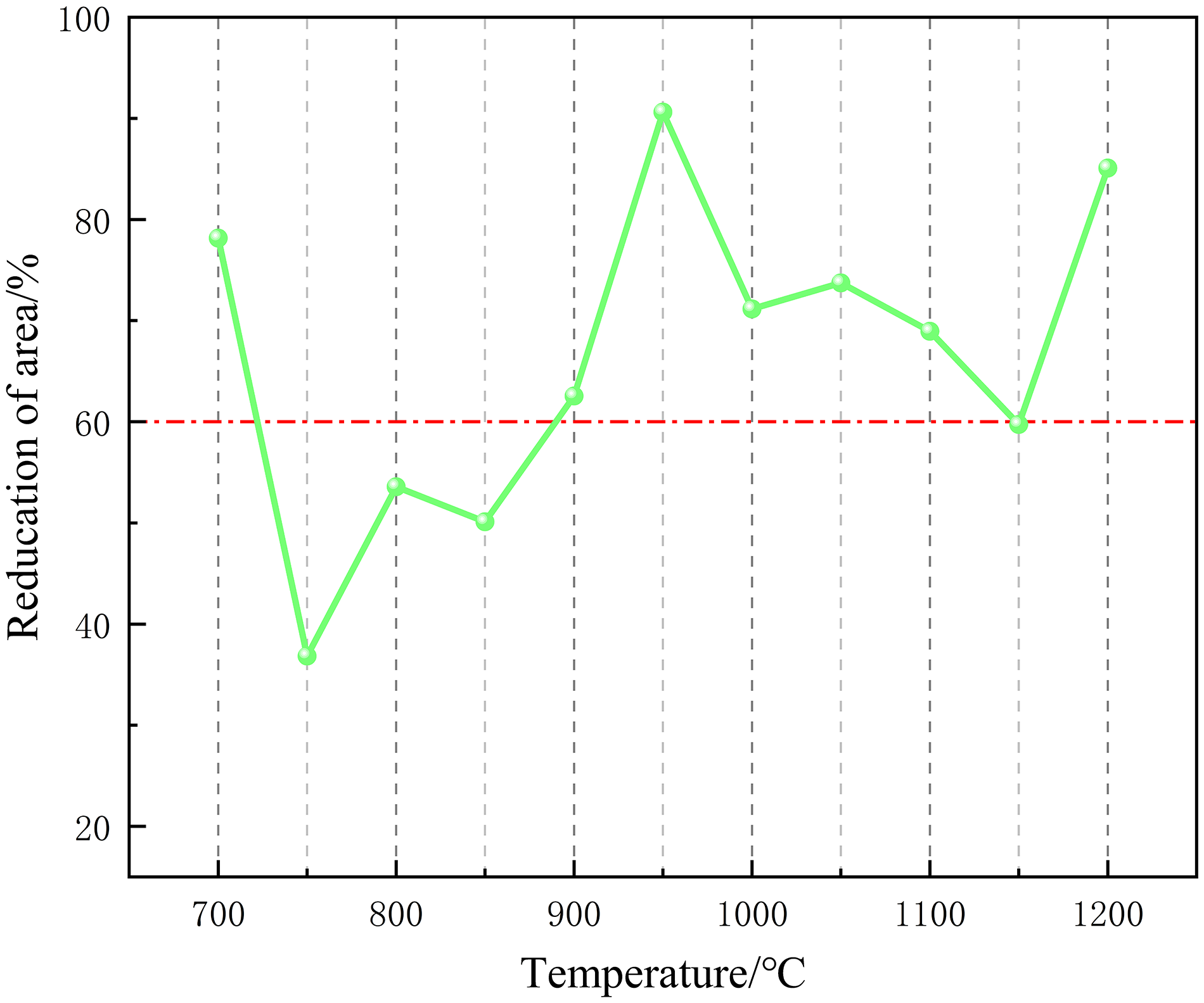
Section shrinkage of steel grades.
Temperature field distribution of cast billet surface
The temperature field of marine 945 steel casting billet under this working condition was calculated by using ProCast software to establish a two-dimensional solidification heat transfer model. Among them, in the calculation, the following assumptions are made: (1) neglect the complex heat transfer in the direction of billet pulling and near the curved moon surface, and simplify it to a simple two-dimensional heat transfer; (2) assume that the billet is cooled uniformly on the inner surface of the same section in the two-cooling zone; (3) assume that the casting billet inner and outer arcs are the same in the way of heat transfer and (4) neglect the actual temperature difference of the molten steel. The initial conditions and boundary conditions of the model concerned are set with reference to the literature.
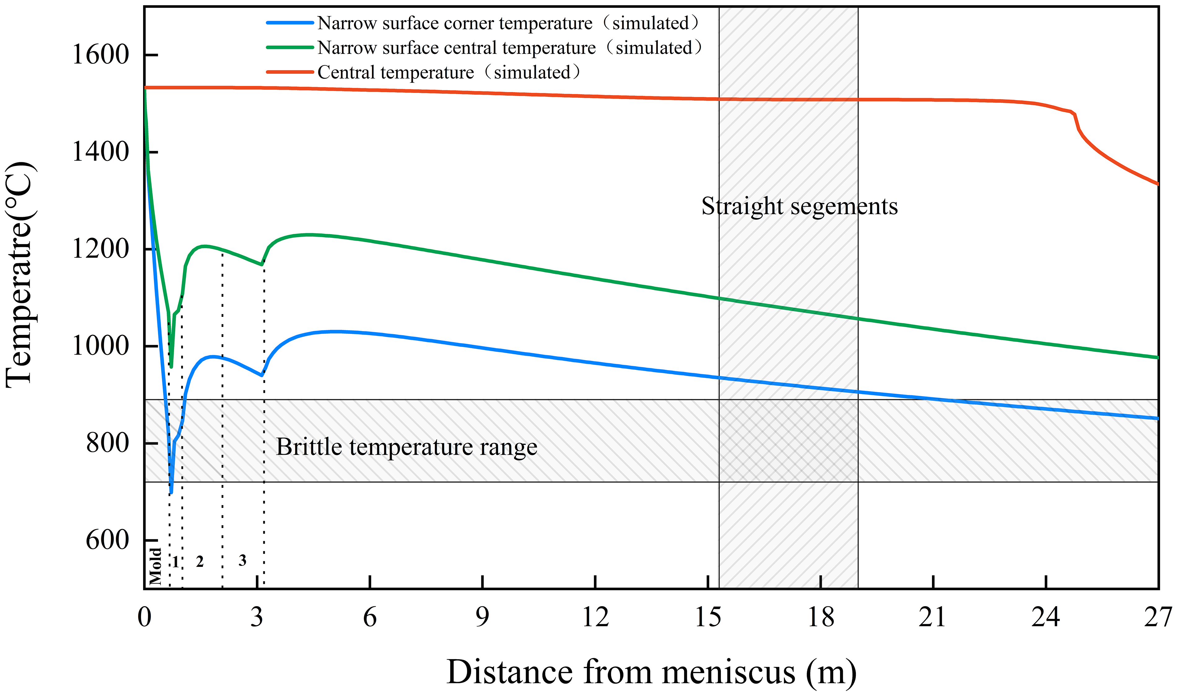
The temperature measurement gun was used to measure the temperature of the billet surface at the positions of 15.2, 15.9 and 19.6 m from the curved moon surface, and the error between the temperature measurement results and the calculated value of the model was within 2%, as shown in Figure 8, which indicates that the model can accurately describe the temperature change of the billet surface. As shown in Figure 6, when the billet comes out of the crystallizer again, the temperature at the centre of the narrow surface of the billet decreases to about 970°C, while the temperature at the corners of the narrow surface of the billet decreases rapidly to about 624°C. When the billet enters the second cooling zone, the billet has a significant temperature return. When the billet enters the straightening section, the temperature of the corner of the billet is in the range of 805°C to 863°C, and the temperature of the centre of the narrow face is in the range of 939°C to 1026°C.
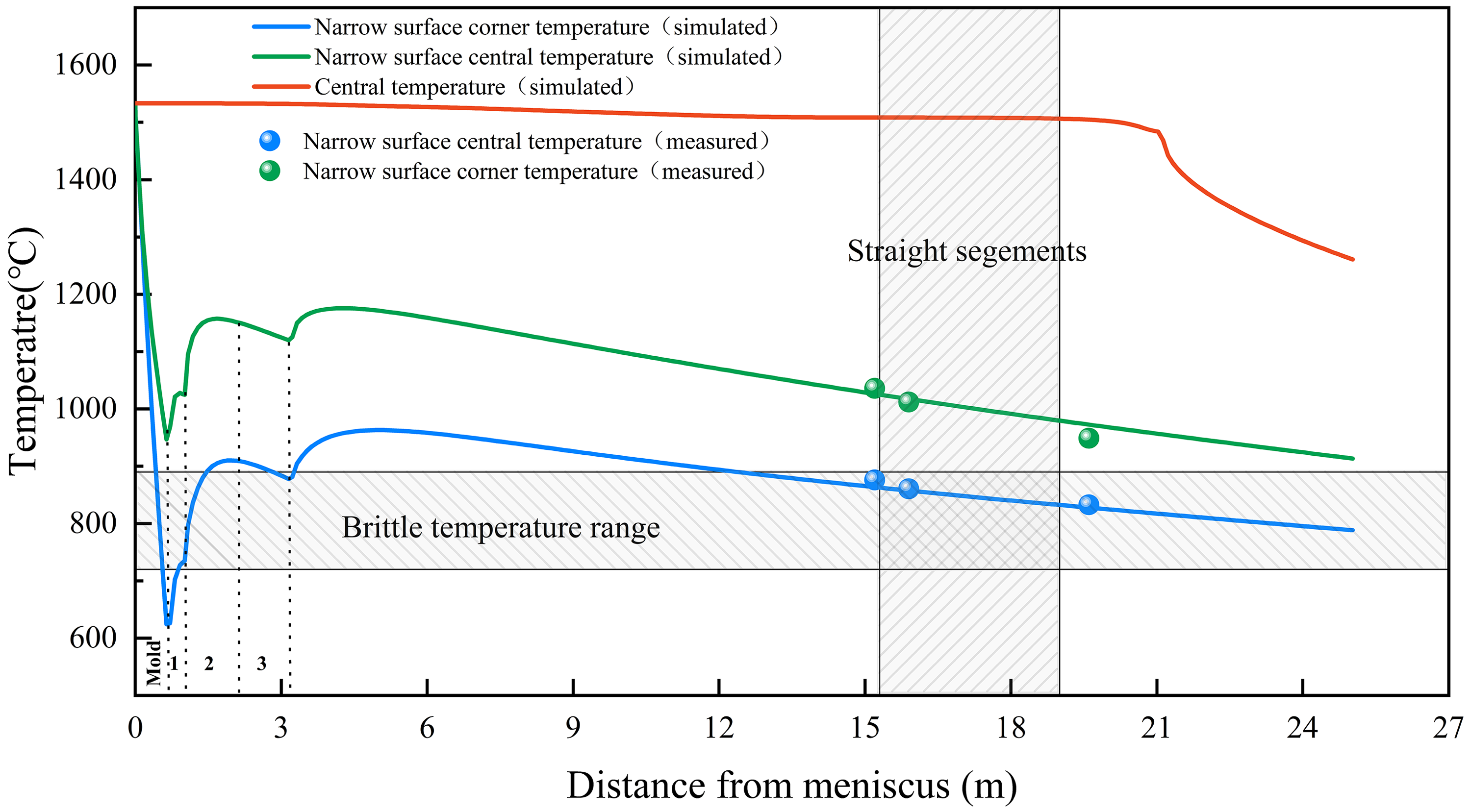
Numerical simulation calculation results and validation.
Analysis of the causes of crack generation
For the generation of corner cracks, it is believed to be caused by the following four aspects:
The ship with 945 steel as a sub-inclusion crystal steel, solidification inside the crystallizer will occur when the inclusion crystal reaction, billet shell volume contraction is larger, will cause the billet shell and the crystallizer wall between the air gap generated, while deeper vibration marks as well as depressions (as shown in Figure 1) will reduce the efficiency of heat transfer, resulting in non-uniform density of heat flow, billet shell thickness growth is not uniform, and is prone to cause a large stress concentration. At the same time, due to the slow heat transfer, in the occurrence of austenite to ferrite transformation at the same time, there are a large number of pre-eutectic ferrite production, and ultimately the formation of pre-eutectic ferrite film, shown in Figure 5. Since the ferrite strength is only about one-quarter of the austenite, it is easy to produce stress concentration. Al2O3-type inclusions irregular shape is a high melting point of brittle inclusions, destroying the continuity of the steel matrix organisation, continuous casting billet in the straightening process received under the action of the external force, the corner containing Al2O3 inclusions in the region is more likely to reach the stress limit, resulting in the generation of corner cracks. According to the high-temperature tensile test, the third brittleness interval of the billet in the range of 720°C to 890°C, in the straightening area of the billet corner temperature falls within this interval, so it is considered that this is caused by one of the reasons for cracks.
According to the results of previous studies, the precipitation of the second-phase particles in the micro-alloyed steel can also cause the generation of corner cracks, but the second-phase particles AlN, TiN, etc. were not found inside the cracks, so the cracks are not considered to be caused by the precipitation of the second-phase particles for this steel grade.
Process optimisation and results
According to the above analysis, the reasons for cracks are mainly due to the uneven heat transfer inside the crystallizer, the presence of Al2O3 inclusions inside, and the temperature of the cast billet corners falling in the third brittle interval during the straightening section. Therefore, the control of corner cracks is mainly from three aspects:
Change the deoxidising method, adopt Si, Mn deoxidising instead of Al deoxidising, so as to avoid the generation of Al2O3. From the perspective of deeper vibration marks on the surface of the cast billet as well as improvement of heat transfer uniformity inside the crystallizer, select a protection slag with high melting point, compared with the original protection slag, the content of Al2O3 was increased and the content of Na2O was reduced, the melting point of protection slag increase 65°C, and the optimised composition of the protection slag are shown in Table 5.
Optimised protection slag composition.
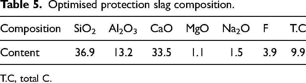
T.C, total C.
(3) When straightening the cast billet, the temperature of the cast billet corner should avoid the brittle zone. Generally through the bending straightening in the ‘cold line’ and ‘hot line’ two ways to avoid the brittle zone of the steel, using the ‘cold line’ method, the billet surface temperature is lower than the brittle zone temperature. Interval, but this method requires high-temperature control, if the temperature control is not easy to produce subcutaneous cracks, and strong cold easily lead to uneven surface temperature of the billet. Using the ‘hot line’ method, the surface temperature of the billet is higher than the brittle zone temperature but will increase the tendency of liquid level fluctuations. Considering that the steel is sub-package crystal steel, billet in the crystallizer solidification, volume contraction is larger, easy to cause uneven growth of billet shell, increase crack sensitivity, so by using ‘hot line’ way, reduce the amount of water cooling the crystallizer and the second cooling zone water to improve the surface temperature to avoid the brittle zone, the optimisation of the cooling water parameters. The optimised cooling water parameters are shown in Table 6, and the gas volume of each circuit in the second cooling zone remains unchanged.
Optimised cooling water parameters.
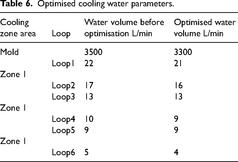
Based on the optimised cooling water table, the surface temperature change of the optimised cast billet was calculated using the established solidification heat transfer model, and the results are shown in Figure 9. After reducing the amount of water in the crystallizer and the amount of water in the second cooling zone, the corner temperature of the cast billet is around 680°C when it leaves the crystallizer, and the corner temperature is increased by 56°C. When the cast billet is straightened, the corner temperature is in the range of 905°C to 935°C. Theoretically speaking, the optimised cooling water parameter can make the corner temperature of the cast billet avoid the brittleness zone of 720°C to 890°C effectively, which reduces the occurrence of corner cracks.
Simulation results of billet temperature after water quantity optimisation.
Industrial tests were carried out according to the above optimisation scheme, and the results are shown in Figure 10, where the frequency of crack occurrence was reduced from 6.3 to 2/m, and the number of cracks and penetration length were significantly reduced.
Crack morphology of optimised cast billet.
Conclusion
In this article, by dissecting the corner cracked specimen of marine 945 steel casting billet, analysing the information of internal inclusions composition of the crack, metallographic organisation around the crack, as well as determining the high-temperature brittleness interval of this steel grade through Gleeble thermal simulator, simulating the temperature change of the surface of the cast billet, and finally clarifying the reasons for cracks, and accordingly carrying out the optimisation of the process, and draws the following conclusions:
The steel grade does not have the first and second brittleness intervals, and the third brittleness interval is within the temperature range of 720°C to 890°C; The generation of corner cracks is due to improper deoxidation, uneven heat transfer inside the crystallizer, and unsuitable cooling water parameters; After the optimisation of the crystallizer protective slag, crystallizer water volume, and second cooling water volume, the frequency of cast billet corner cracks was reduced from 6.3 to 2/m.
Footnotes
Declaration of conflicting interests
The authors declared no potential conflicts of interest with respect to the research, authorship, and/or publication of this article.
Funding
The authors received no financial support for the research, authorship, and/or publication of this article.