






Abstract
Exogenous oxide inclusions in continuously cast steel are primarily caused by the entrapment of slag during the key stages of steelmaking processes, including in furnaces, ladles, and molds. To prevent contamination and maintain steel cleanliness, operators often halt the ladle and tundish processes before the onset of “slag vortexing,” as this phenomenon can significantly degrade product quality by entraining unwanted slag into the molten metal. To study the vortexing phenomenon, previous studies have used water model experiments to simulate the casting process. To ensure valid comparisons between the two, the dimensionless numbers in both the actual casting process and water models must be matched. Hence, it is significant to identify the critical non-dimensional numbers that influence the vortexing phenomenon (Rankine vortex formation). A thorough scrutiny of the current literature reveals that no studies have been made in this direction so far. To address this potential gap, the current study aims to identify the key dimensionless numbers that affect air-core vortexing in the liquid draining process and to determine their individual impact on this phenomenon. The study investigates how these dimensionless numbers influence the formation of air-core vortices during water drainage, simulating molten metal behavior. It specifically examines the Characteristic Volume of the Air Core, along with the dimensionless recession velocity, which is used exclusively in the pre-critical height regime. The results demonstrate that these dimensionless numbers significantly influence vortexing behavior, with the strength of the air core being controlled by both airborne and waterborne Taylor vortices. Additionally, the study reveals the effects of these dimensionless numbers in the pre-critical regime, an aspect not previously reported in the literature. These findings offer valuable insights for optimizing continuous casting processes in steel and other metals.
Introduction
When a rotating liquid column drains out through an orifice, a “kink” like structure develops at the free surface of the draining liquid, which gradually evolves into an air core vortex that extends towards the orifice (drain port). The free surface height of the draining liquid at which this vortex reaches the drain port is referred to as the “critical height” (h c ) 1 and this parameter has been used by many researchers to assess the intensity of Rankine vortex formation or air core vortexing.2–4 A series of studies by Prabhu and Kumar 5 , Prabhu et al. 6 , and Prabhu and Kumar 7 confirmed that critical height alone cannot adequately quantify the strength of an air core vortex. To address this issue, Prabhu et al. 6 introduced a parameter known as the non-dimensional characteristic volume of the air core to quantify vortexing. The characteristic volume of the air core, as defined by Prabhu et al., 6 is the volume of air within an imaginary vertical cylindrical column situated directly above the obstructed region at the drain port, extending up to the free surface level when the critical height is attained, and the same is illustrated in Figure 1. This volume is non-dimensionalized with the cylindrical volume above the drain port till the initial height (hi) of the liquid column.
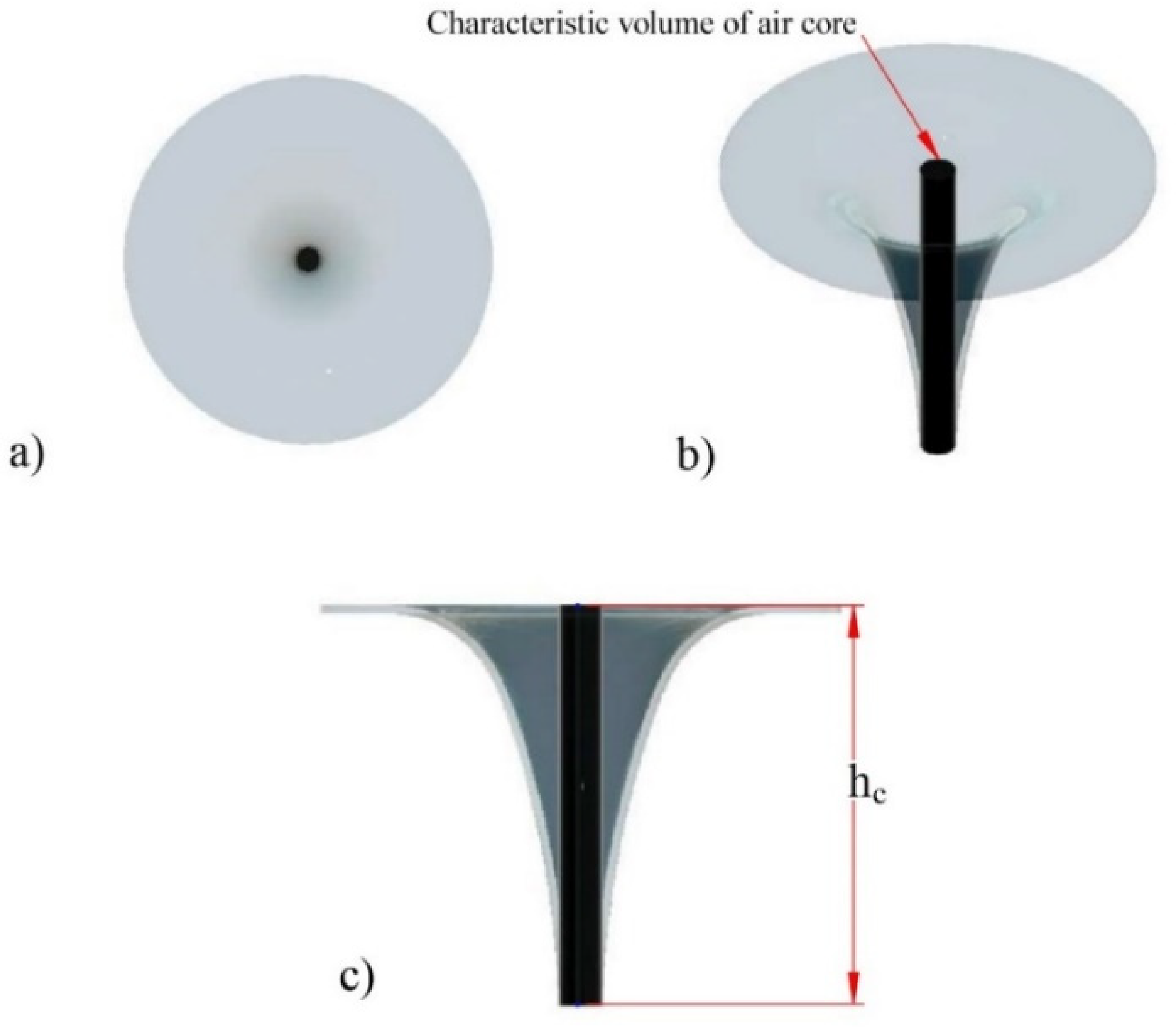
Schematic sketch of air core showing characteristic volume of air core: (a) top view, (b) isometric view, and (c) side view.
Once an air core reaches the drain port, it disrupts the fluid flow, reducing the discharge of draining liquids. In casting systems, the formation of an air core vortex in the tundish (a rectangular vessel used as the final metallurgical container in continuous casting process 8 ) and in the ladle (a large container used for transporting and pouring molten metal into the tundish 8 ) can lead to serious repercussions in the quality of the finished metal products. 9 This challenge, along with the need for cost-effective solutions, drives the motivation for the current study. A typical depiction of an air core vortex at the instance of critical height formation is illustrated in Figure 2.
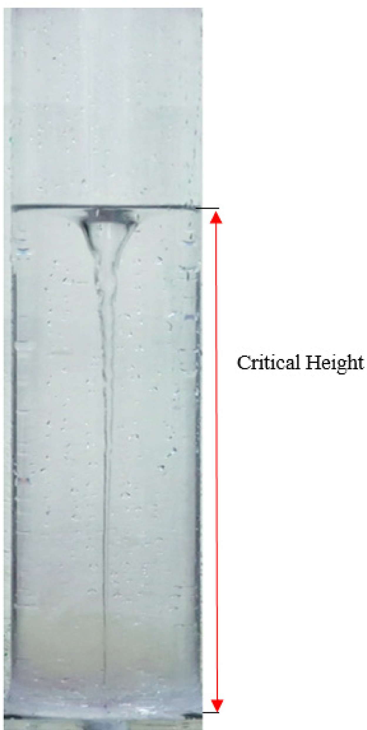
A typical air core vortex at the instance of critical height formation. 10
Lubin and Springer 11 found that the critical height of draining liquids when concentric drain ports are employed remains unchanged, irrespective of the initial height (h i ). They established a functional relationship between critical height, fluid density ratio, and liquid discharge. Studies by Zohu and Graebel 12 corroborated this functional relationship, further demonstrating that liquid rotation, tank size, and drain outlet size influence the critical height. They deduced a relationship based on non-dimensional parameters to characterize vortexing. Ajith Kumar et al. 13 demonstrated that vortex strength, represented by the critical height, is influenced by the eccentricity of drain ports. They report that, for concentric ports, the air core (Rankine vortex) fails to reach the drain port if the ratio of port size to tank diameter is below 0.3. Additionally, Ajith Kumar et al. 14 observed that this critical ratio (port size to tank diameter) increases with the eccentricity of ports.
Nazir and Sohn15,16 investigated the effects of swirl and axial velocities on vortex air core, revealing that temperature and initial fluid height play a significant role in vortex formation. Prabhu et al. 17 observed that vortexing can be mitigated by using two identical drain outlets positioned at equal eccentric distances from the tank center. Gowda 18 compared the draining behavior in square, rectangular, and cylindrical tanks, highlighting improved air core mitigation in tanks with non-circular cross sections. Rathur and Ghosh 19 observed reverse flow occurring at high drain port eccentricities in square tanks. Prabhu et al. 20 found that octagonal ports are more effective than traditional circular drain ports in suppressing air core vortices. Furthermore, Prabhu and Kumar 7 successfully employed cruciform-shaped drain ports to mitigate air vortexing. Studies have also documented the application of several types of external devices for vortex suppression, such as dish-shaped (or cup-shaped) suppressors,21,22 vane-type suppressors,23,24 meshed plates 25 and disc-type suppressors. 26 These devices are installed within the tank, where their interaction with the draining fluid helps reduce external disturbances like rotational flow, thereby effectively preventing the development of air core vortices. Prabhu et al. 10 classified this kind of suppression strategy as intrusive vortex suppression strategy. All these studies provide valuable insights into various techniques for controlling vortex formation during liquid draining processes. It was found that few studies13,27 have explored the effect of non-dimensional numbers on vortexing. However, these studies were conducted without keeping one non-dimensional number constant while investigating the impact of others on vortexing. As a result, they fail to isolate the sole effect of a particular non-dimensional number on the vortexing phenomenon. This research gap highlights the need for more focused studies that examine the individual effects of non-dimensional numbers, that is impact of a particular number holding the remaining parameters constant to ensure accurate comparisons.
It should be noted that drain tanks are frequently subjected to external disturbances, involving thermal28–30 and mechanical 31 factors. Sankaranarayanan and Guthrie 9 noted that various mechanical disturbances can induce rotational flows during the steelmaking process. These disturbances can arise from sources such as furnace tapping, argon and induction stirring, ladle transportation, and turret rotation. As a result, these disturbances impart rotational motion to the liquid within the tank, which can persist due to inertial effects and exhibit delayed responses depending on the nature and timing of the disturbances. The study by Sankaranarayanan and Guthrie 9 also emphasize that even small rotational movements in the ladle or tundish can lead to the formation of a vortex funnel, which in turn causes slag entrainment. Slag entrainment in continuous casting molds can cause severe defects in steel products. 32 These entrainments in casted metals can seriously affect their mechanical properties, which is not advisable in many engineering applications.33,34
In addition to the formation of vortex funnels, continuous casting processes face challenges such as clogging of submerged entry nozzles (SENs). In continuous casting, when the wall temperature of SENs drops below the melting point of the parent metal, a solid crust forms on the nozzle walls, leading to clogging. This phenomenon negatively affects tundish-mold systems by reducing their effective diameter compromising product quality. 35 Nozzle clogging restricts the flow of molten metal, directly reducing the flow rate and potentially causing significant pressure drops in the system. This reduction leads to flow asymmetry34,36 and increased turbulence. 37 Additionally, clog in nozzles can induce inclusion defects in solidifying metals, adversely impacting their mechanical properties. 32 Beyond these effects, clogging also alters the effective diameter of SENs, modifying the shape of drain ports. According to the previous studies,38,39 the size and shape of drain ports play a crucial role in vortex formation. These clogging-induced changes in drain port geometry can intensify vortexing, increasing the risk of defects and reducing the overall quality of the cast metal. 32
Therefore, analyzing the drainage of liquid metals through SENs is essential to understand how air-core vortices influence the draining process and devise means to eliminate their ill effects. It is important to note that prior research works have often treated the flow of molten alloys and metals as that of Newtonian fluids. For instance, Kato et al. 40 found that molten bulk glass alloy (Pd40Ni10Cu30P20) behaves as a Newtonian fluid under low shear stress conditions. Similarly, Korolczuk-Hejnak and Migas 41 examined various steel grades (90CrV6, DHQ3, 34CrNiMo) and observed Newtonian fluid characteristics when the temperatures were slightly above the liquidus temperature. As a result, earlier studies5,33,34 have used water to simulate molten metal flow, assuming this approach to be valid due to the behavior of water as a Newtonian fluid.
Recent studies have increasingly employed low-melting-point liquid-metal models such as GaInSn for investigating flow structures and magnetohydrodynamic (MHD) phenomena relevant to continuous casting systems. Unlike conventional water models, GaInSn-based studies can additionally reproduce electrical conductivity effects associated with molten steel, thereby enabling investigation of electromagnetic stirring, Lorentz-force-driven flow behavior, and rotating magnetic field-induced vortex structures.42–44 Such studies provide additional physical realism for analysing MHD effects in metallurgical systems.
Due to the difficulties associated with directly observing air-core vortexing phenomena in molten steel and the temperature constraints of metallurgical vessels, several previous investigations45,46 employed water at room temperature as a working fluid for studying flow-field distribution. Owing to their simplicity, optical accessibility, and ability to reproduce important hydrodynamic characteristics under appropriate dynamic similarity conditions, water-model-based investigations continue to remain widely adopted for studying vortex evolution and flow behavior in metallurgical vessels. Wang et al. 45 and Fogaras et al. 46 also reported that kinematic viscosity of molten steel at 1600 °C differs by less than 10% from that of water at 20 °C, highlighting a close similarity between the two. As a result, modeling liquid metal as water serves as a reasonable and widely accepted approximation for simulating flow patterns of molten steel in metallurgical vessels such as converters, ladles, and tundish. While useful as an initial approximation, this approach of directly comparing dimensional parameters—such as kinematic viscosity—between water at room temperature and molten steel at high temperatures fails to capture the broader complexity of the casting process, where the flow behavior is additionally influenced by electromagnetic effects, 47 thermal gradients and solidification, 36 slag–metal interfacial phenomena, 8 and multiphase gas–metal interactions. 32 Therefore, to more accurately simulate the behavior of molten steel in metallurgical vessels, it is essential to consider the governing dimensionless numbers and dynamic similarity conditions that control the relevant flow features and vortex dynamics during the casting process. Dynamic similarity ensures that the scaled water model replicates the relevant flow features and vortex dynamics of molten steel during the casting process. The dimensionless groups capture the influence of factors like inertial forces, gravitational effects, and surface tension, which significantly affect flow patterns, vortex formation and its evolution in molten steel. Unlike raw dimensional properties, these groups provide a more generalized and scalable framework for analyzing vortex behavior. The lack of such an analysis in the existing water modeling studies presents a critical research gap, as it overlooks the intricate dynamics of the casting process that could lead to misleading or incomplete conclusions. By incorporating the appropriate dimensionless numbers and ensuring dynamic similarity, a more rigorous and reliable comparison between water models and molten steel can be made, thereby improving the fidelity of simulations for real-world casting processes.
By keeping this impetus in mind, the current study focuses on deriving the relevant dimensionless parameters pertinent to vortexing phenomenon using Buckingham's pi theorem.
48
In the current study, the nondimensional characteristic volume of air core (Vch) is considered as the dependent variable. From the studies of Prabhu et al.,
6
for a rotating liquid column undergoing draining, it was found that Vch depends on tank diameter (D), drain port diameter (d), kinematic viscosity of draining liquid (ν), acceleration due to gravity (g), surface tension of draining liquid (σ), initial liquid height (hi) and angular velocity of the liquid column (ω). This is represented in equation (1). This study has seven independent variables and three fundamental dimensions, viz. length, mass and time. According to Buckingham's pi theorem,
48
four non-dimensional groups or π terms can be obtained. Three repeating variables—d, g, and σ—are considered in this study, representing geometric, kinematic, and fluid properties, respectively. After applying Buckingham's pi theorem, four π terms are obtained and they are provided in equations (2) to (5). It should be noted that π1 and π3 are non-dimensional port diameter and initial height, respectively, and their effect on vortexing phenomenon is already studied by Nazir and Sohn
49
, Sohn et al.
50
and Nazir and Sohn.
15
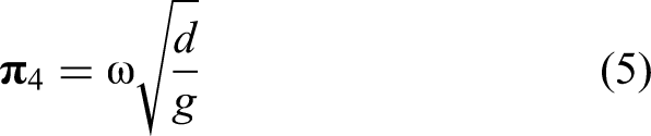
It could also be noted from previous literature50,51 that π2 and π4 are expressions for Reynolds number (Re) and Froude number (Fr), respectively. It is also interesting to note that there is no π-term, which is a function of surface tension (σ). This means surface tension has no influence on air core vortexing phenomenon and this inference from the current study is in agreement with the results of previous investigations.16,52




Previous studies27,50,51 also reported the effects of the Reynolds number (π2) and Froude number (π4) on the air core vortexing phenomenon. However, the problem with these studies is that the results presented reveal the combined influence of Re and Fr and therefore, individual effects of these dimensionless numbers are not known. This is because a change in one dimensionless quantity affects the other, making it impossible to study the sole effect of any single dimensionless quantity in the aforementioned studies. It is important to note that, to study the effect of a specific non-dimensional number on vortexing, other non-dimensional numbers must be kept constant. While this can be quite challenging in experimental investigations, it is relatively easier to achieve it in numerical studies. Therefore, a numerical simulation is conducted in the present study, and the details are provided in the subsequent sections.
Numerical methodology
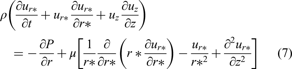
To study the phenomenon of air-core vortex formation during liquid drainage from a cylindrical tank, a two-dimensional axisymmetric numerical simulation was conducted using a commercial CFD solver, viz., ANSYS Fluent 2023R2. By assuming axisymmetry, the vortex formation process was effectively captured in this numerical analysis. As previous studies report,2,49,53 the axisymmetric assumption helps to capture the key features of the vortexing phenomenon while reducing computational costs. Governing equations such as continuity, radial and axial momentum conservation equations, viz., equations 6, 7 and 8 respectively, were solved to describe the swirling and draining flow in the tank.

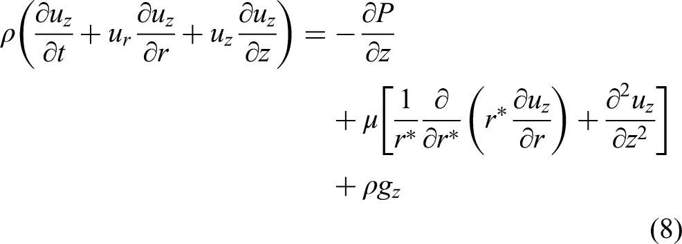
The Volume of Fluid (VOF) method was employed to track the interface between the two phases (air and water). Park and Sohn
53
successfully simulated the vortex air-core phenomenon using a laminar-viscous model together with the VOF approach, thereby demonstrating the effectiveness of the VOF method in capturing the flow field. Accordingly, the VOF method was adopted in the present study to capture the evolution of the air core. Therefore, in addition to the basic governing equations provided in Equations (9a), (9b), and (9c), the following volume fraction equations were also solved:



In this study, the laminar-viscous model is employed to simulate the air-core flow field, using a numerical solver similar to the one used by Park and Sohn.
53
The top open end of the tank was defined as a pressure inlet, the bottom-draining end of the drain port as a pressure outlet, and the tank walls were assumed to be stationary. The surface tension coefficient between water and air (25
Custom Field Functions were used to introduce an initial swirl to the liquid column before the start of iterations. As shown in Figure 3, an initial liquid height of 300 mm, measured from the bottom of the drain port to the free surface of the water column, was initialized as the “water phase,” with the region above the free surface was set as the “air phase.” The Pressure-Implicit with Splitting of Operators scheme was used for pressure-velocity coupling to solve the pressure-based equations. The Pressure Staggering Option (PRESTO!) was applied to use a staggered grid for pressure interpolation, improving efficiency and compatibility with both structured and unstructured meshes. Additionally, the Non-Iterative Time Advancement (NITA) formulation was employed in these calculations.
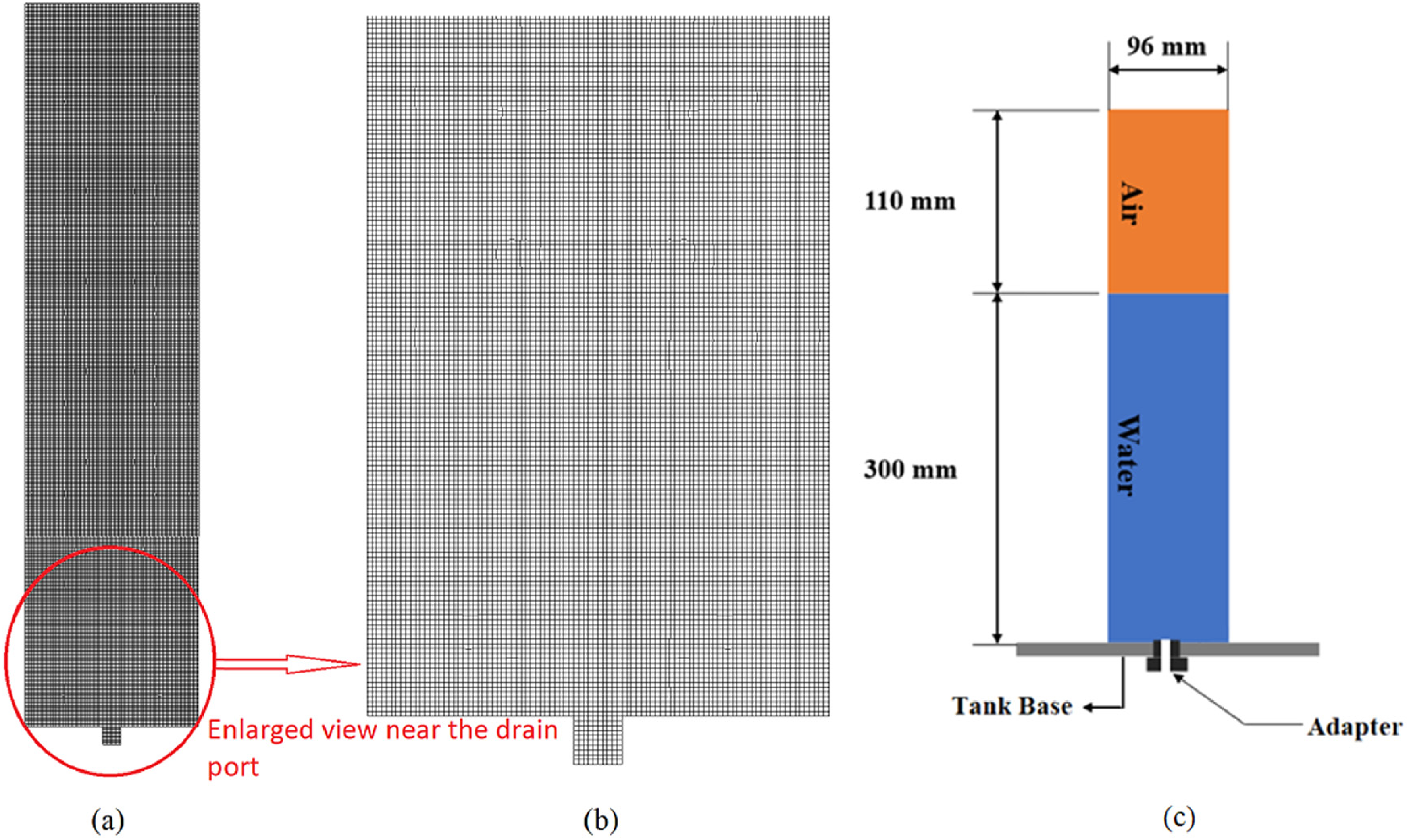
Computational mesh and schematic layout of the present study.
To determine the optimal mesh size for the simulation, a grid independence study was performed using a typical case with d = 10 mm and n = 200 r/min. The results of this study, shown in Table 1, indicated that a mesh with 19,730 cells would be suitable for the computational analysis. The computational mesh employed in the present study after performing the grid independence analysis is shown in Figure 3(a), while an enlarged view of the mesh near the drain port is presented in Figure 3(b). A computational study was conducted in a cylindrical tank with a diameter (d) of 96 mm and a height of 410 mm, as schematically illustrated in Figure 3(c).
Grid independency study
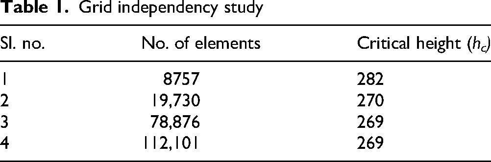
Table 2 presents the variation of dimensionless critical height (Hc = hc/hi) with initial fluid rotation (n), where the numerical results are compared with both experimental data and published findings. To validate the computational solver, an experimental study was conducted using a cylindrical glass tank with a flat base and a concentric drain port of 10 mm in diameter. The cylinder was first securely mounted on a rotating disc and then filled with water to a height of 300 mm (hi = 300 mm). Subsequently, it was rotated using the setup as shown in Figure 4. The cylinder was rotated at speeds ranging from 180 to 240 r/min, with increments of 20 r/min, for a duration of four minutes. After this period, the cylinder was stopped, and the fluid was drained out. During the draining process, an initial dip formed at the liquid surface, which then extended vertically downwards and developed into a complete vortex air core. The critical height (hc) was measured when the tip of the air core just entered the drain port, using a graduated scale vertically attached to the outer surface of the tank. The experimental and numerical results showed a deviation of less than 2%, indicating good agreement, as shown in Table 2. Therefore, the computational solver used in this study is considered validated.
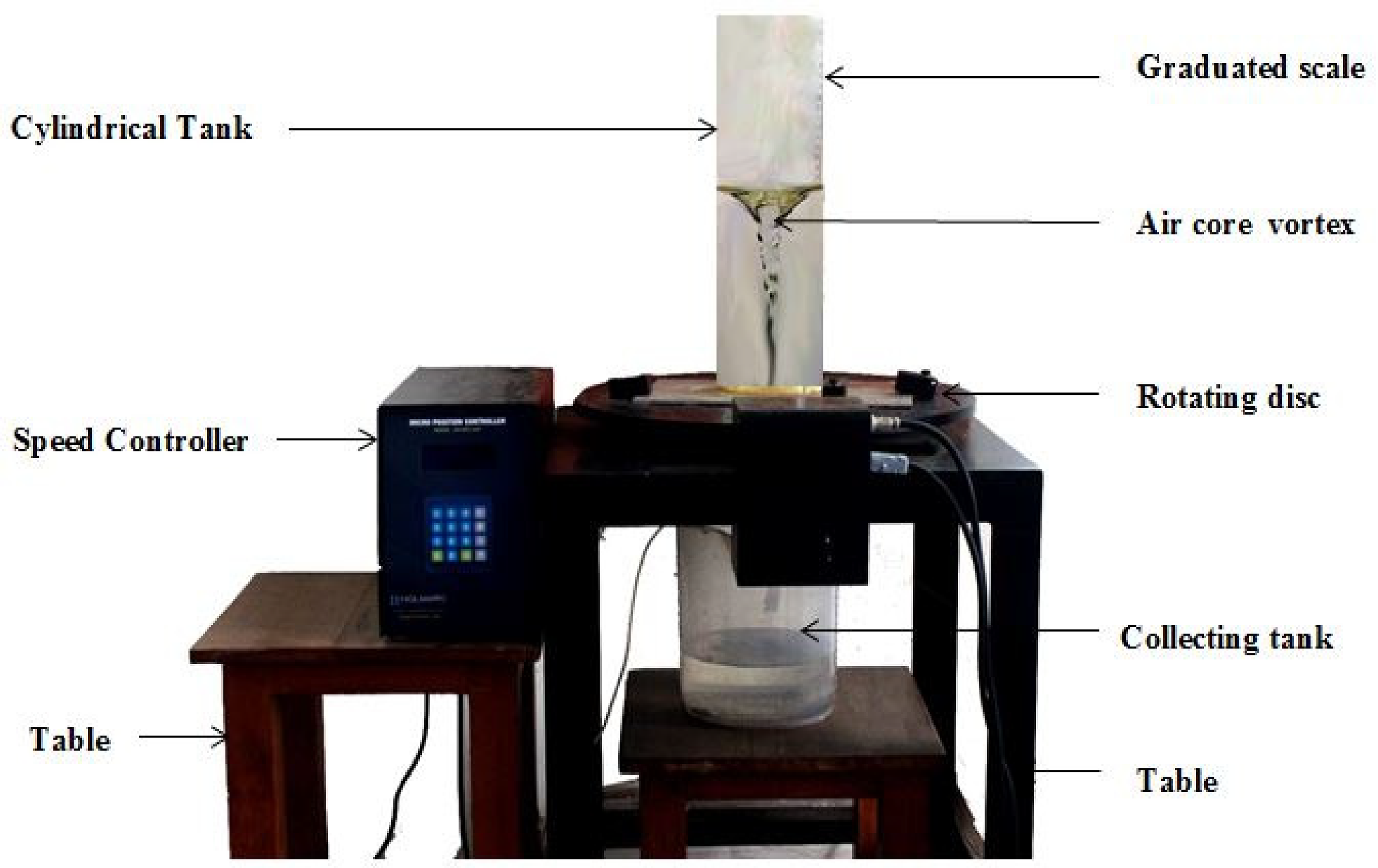
Experimental setup used for validation.
Validation of numerical results with published and experimental data

Results and discussion
Dimensionless numbers relevant to the air-core vortexing phenomenon in liquid-draining tanks are formulated in the previous section, and it is noted that the effects of port diameter and initial height have already been discussed in the previous literature.49,50 Dimensional analysis, along with findings from previous investigations16,52 established that surface tension forces have no significant influence on air-core vortexing phenomenon. Consequently, the current study primarily excludes surface tension effects and places minimal emphasis on the impact of Weber number. Instead, this study focuses on investigating the effects of Froude number and Reynolds number, as these are the primary non-dimensional groups that significantly influence the vortexing behavior. This approach allows for a more detailed understanding of the key factors driving the air-core vortexing phenomenon. Since both Reynolds number and Froude number are functions of angular velocity (ω) and port diameter (d), changes in these parameters will affect both these dimensionless quantities simultaneously, making it impossible to study the sole effect of either of them. This issue is resolved by varying the kinematic viscosity in equation (3) to change Reynolds number, and varying the acceleration due to gravity in equation (5) to change Froude number. This approach allows for the study of the sole effect of each dimensionless number, an imbroglio that has not been addressed by the previous investigators.27,50,51
Moreover, previous investigators27,50,51 considered critical height as a metric to quantify vortexing and examined the effect of dimensionless parameters on critical height. However, as mentioned earlier, studies by Prabhu et al. 6 have shown that critical height is not an appropriate metric for quantifying vortexing owing to the fact that it represents only the onset of air-core formation and does not capture the subsequent evolution of vortex strength. Therefore, this study uses the characteristic volume of air core (Vch) as the parameter to quantify vortexing. The variation of characteristic volume with the Froude number (Fr) and Reynolds number (Re) is illustrated in Figures 5 and 6, respectively. As can be seen, the parametric trends are just opposite to each other. The typical range of non-dimensional numbers applicable to the metal casting process was calculated using the properties of liquid steel from the previous studies. 45 Based on these calculations, the investigated range of Froude number (Fr) in this study was 1.62 to 2.01, while the Reynolds number (Re) ranged from 2 × 10⁴ to 6 × 10⁴. It is illustrated in Figure 5 that an increase in Froude number leads to a drop in Vch, indicating that the air-core vortex is mitigated. Similarly, Figure 6 demonstrates that an increase in Reynolds number results in an increase in Vch, meaning that the air-core vortex is strengthened.
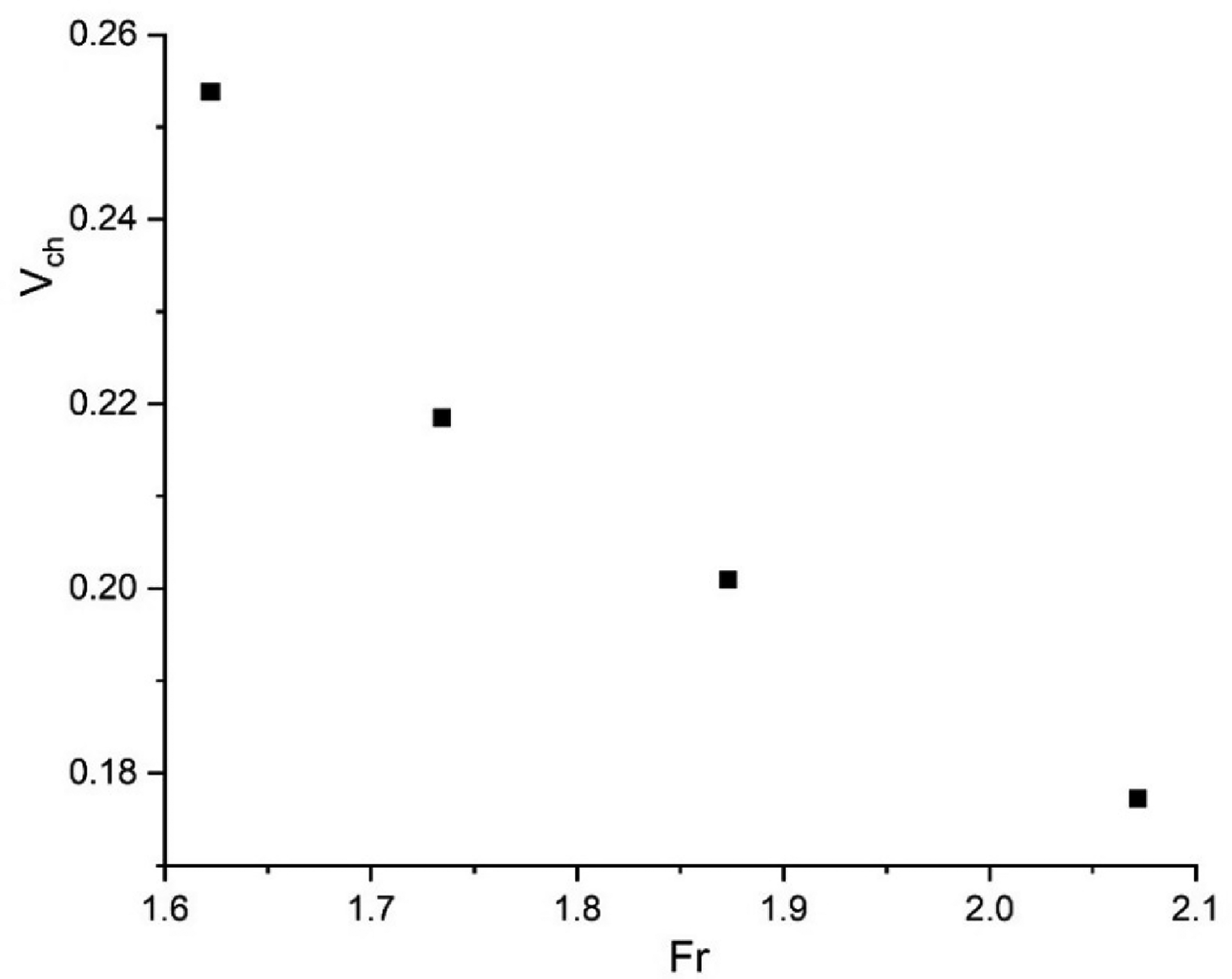
Variation of Vch with Fr.
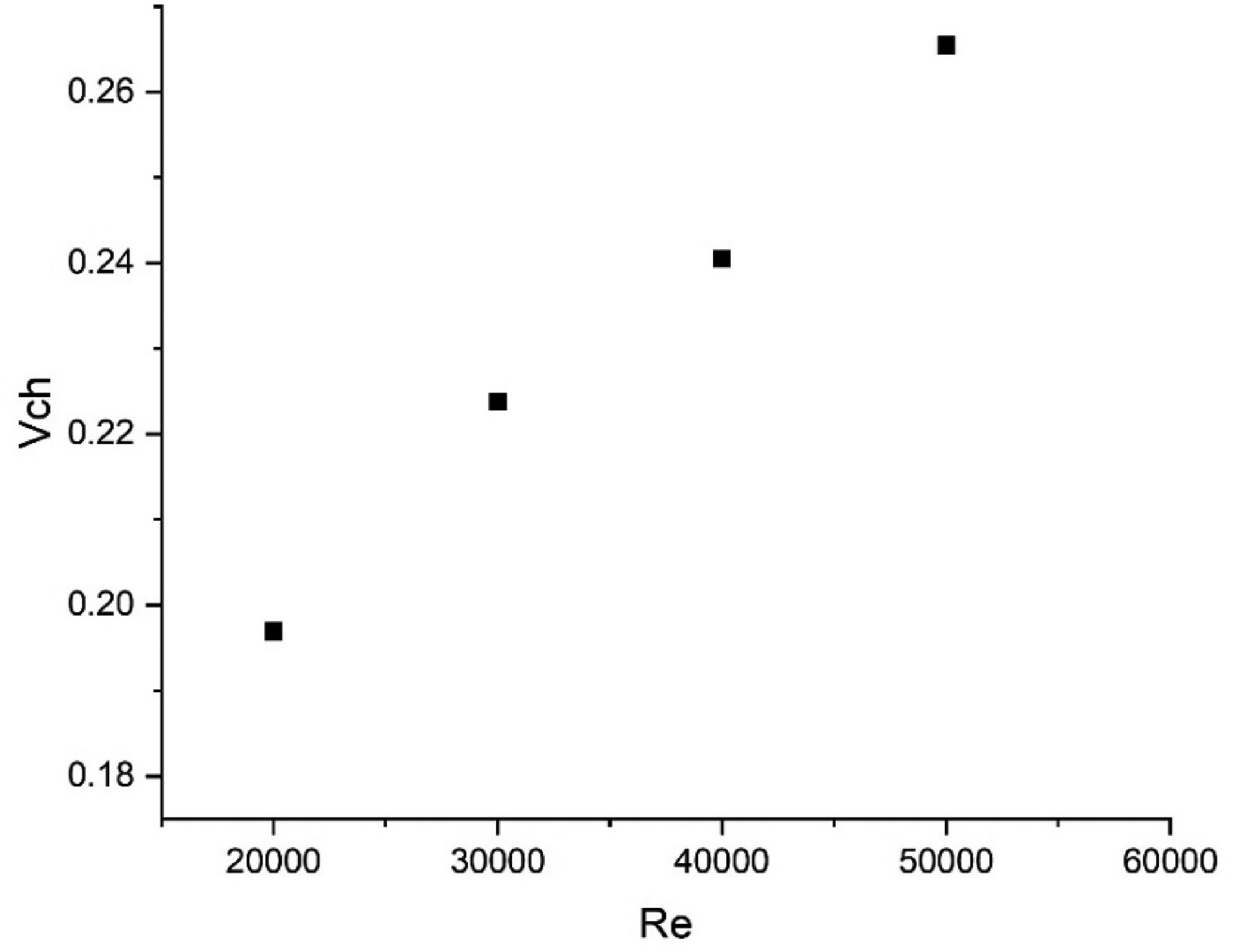
Variation of Vch with Re.
To identify the cause of the aforementioned variation of Vch with Fr and Re, streamlines and volume fraction contours (blue represents water phase and red represents air phase) are qualitatively studied for each value of Froude number and Reynolds number at the instant of critical height formation. Subsequently, the variation of static pressure with respect to these dimensionless parameters is also investigated. The streamlines and volume-fraction contours for different Froude numbers are presented in Figures 7 and 8, while those for various Reynolds numbers are shown in Figures 9 and 10. These figures (Figures 7 and 9) show circulatory flow regions or vortex structures within the air and liquid domains. Sohn et al. 50 identified these vortical structures as “Taylor vortices,” noting that they are initially observed near the cylinder walls. Their expansion towards the center of the cylinder (spatial expansion of the Taylor vortex) can strengthen the ingested air core vortex. 50 In subsequent works following Sohn et al., 50 investigators verified that the expansion of Taylor vortices can be controlled by inserting a disk 26 or applying an external magnetic field 47 to draining liquids. These strategies were shown to mitigate air vortexing, thereby confirming that the spatial expansion of the Taylor vortex is a major factor that strengthens air-core vortices. However, in these studies, Taylor vortices are found to be waterborne, and their effects on the strength of the air-core vortex are mentioned only in relation to their radial expansion. It is worth mentioning here that the current study has made two novel findings that distinguish it from the earlier studies. First, it has been identified from Figure 9 that Taylor vortices can exist in both air and water phases, a phenomenon not previously reported. Second, as shown in Figures 7 and 9, this study reveals that airborne Taylor vortices can undergo expansion in the axial direction also as Fr and Re are varied. This spatial expansion in the axial direction can significantly influence the strength of the air-core vortex. Additionally, the size of these vortices also plays a predominant role in determining the vortex strength.
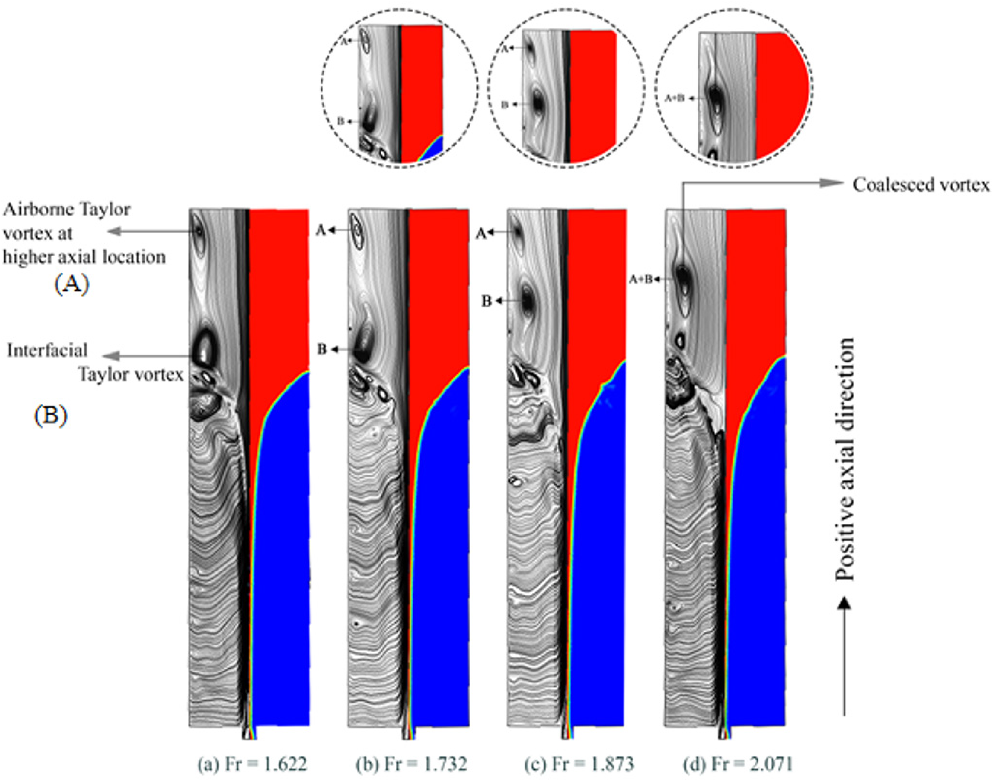
Streamlines merged with volume fraction contours for various Fr values at the instant of critical height formation.
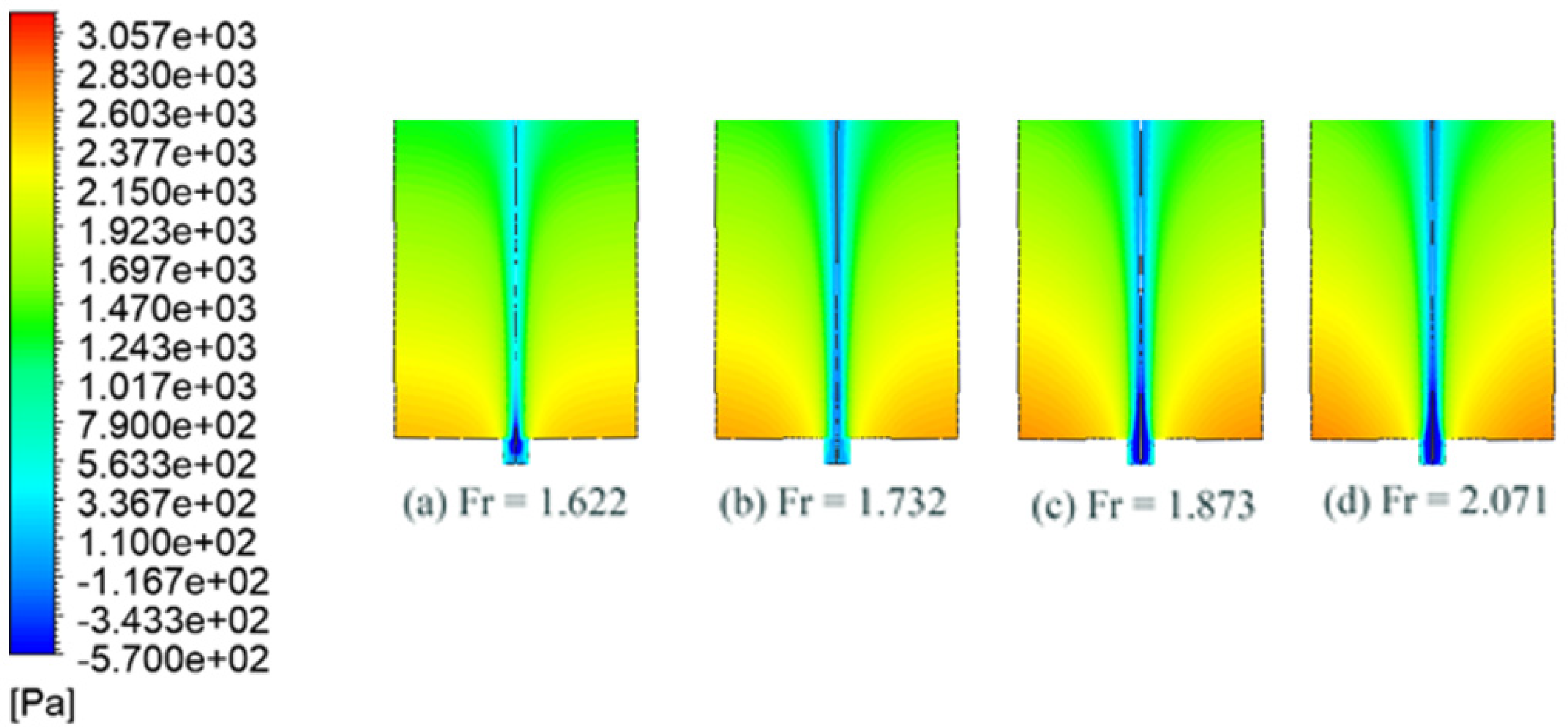
Pressure contours for various Fr values at the instant of critical height formation.
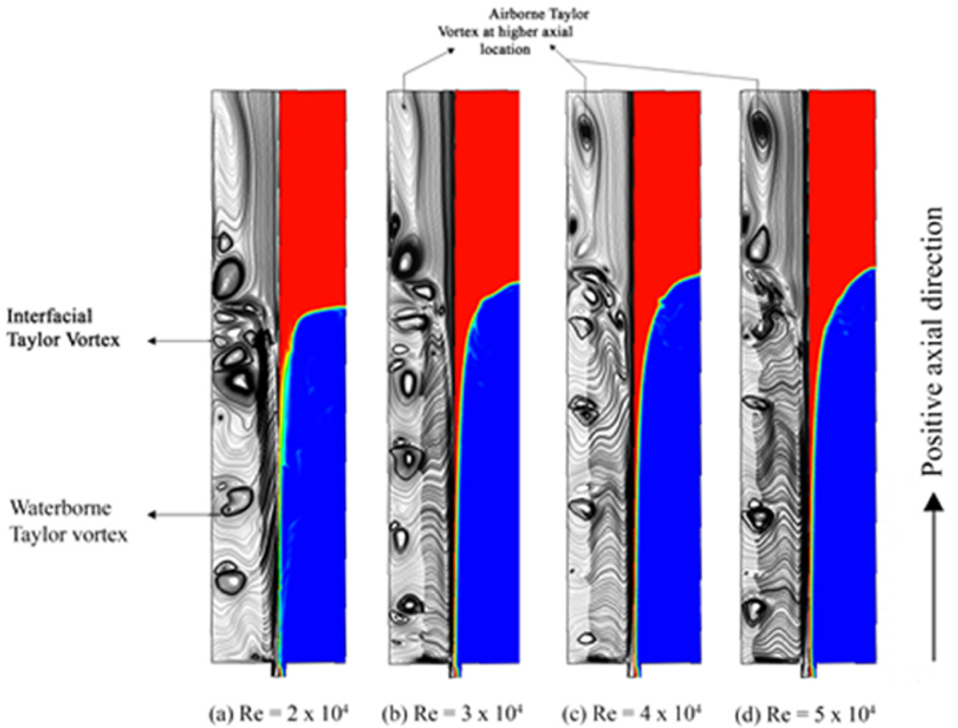
Streamlines merged with volume fraction contours for various Re values at the instant of critical height formation.
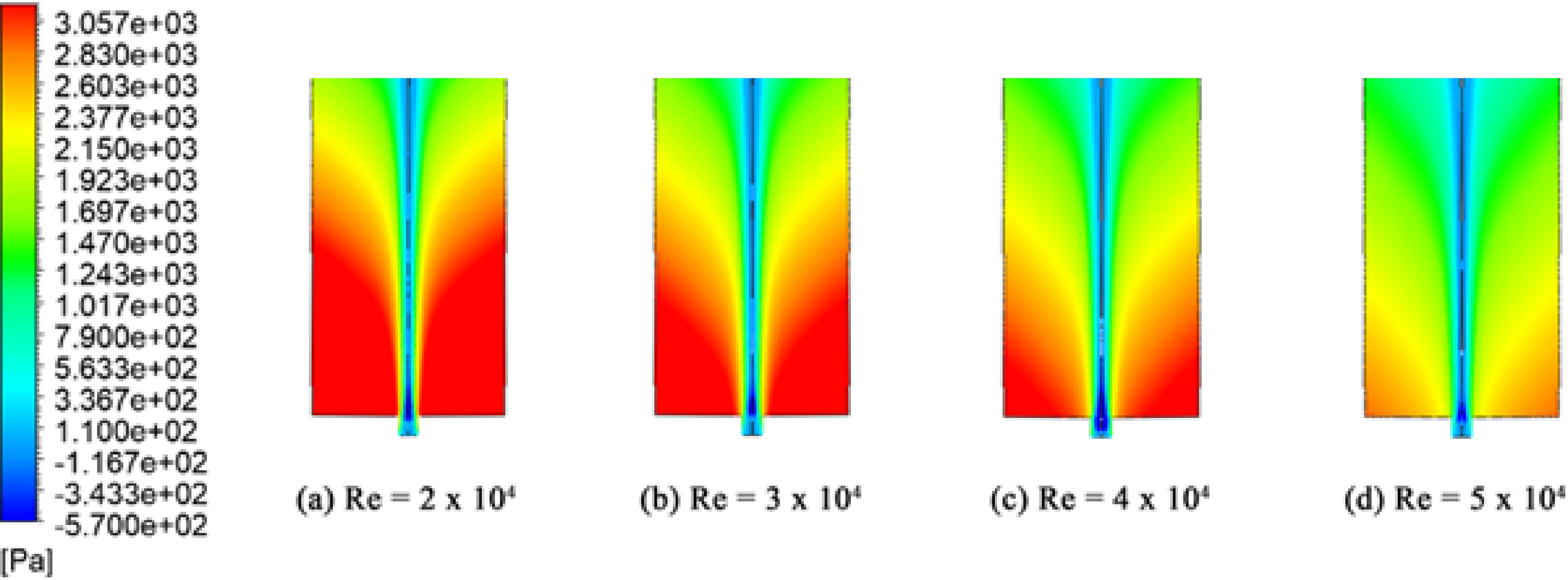
Static pressure contours for various Re values at the instant of critical height formation.
It should also be noted as a limitation of the present investigation that the identified airborne and interfacial Taylor vortex structures are interpreted based on axisymmetric VOF simulations under laminar flow assumptions, consistent with several earlier draining-vortex studies reported in the literature.26,50,53 Although similar secondary vortex structures have been discussed previously in axisymmetric draining configurations, further validation through three-dimensional simulations and/or detailed experimental flow visualization would provide additional confirmation regarding their hydrodynamic characteristics.
It is highlighted here that previous studies on air-core vortex formation primarily discussed waterborne Taylor vortices, whereas the possible existence and axial spatial expansion of airborne Taylor vortices have not been explicitly reported earlier. It is observed from Figure 7 that for Froude numbers ranging from 1.622 to 2.071, no waterborne vortices are present. However, an interesting phenomenon occurs with the airborne Taylor vortex, as illustrated in Figures 7. It is highlighted here that none of the previous studies on air core vortex formation reported the possible existence of airborne vortices, and the current investigation is the pioneer one which brings it to light. At a Froude number of 1.622, Figure 7(a) shows a few small airborne Taylor vortices (marked as B) at the interface, along with a larger airborne Taylor vortex (marked as A) located at farther axial distances (closer to the liquid free surface). As the Froude number increases to 1.732 and then to 1.873, the larger airborne Taylor vortex, seen in Figure 7(a), appears to be pulling the interfacial airborne Taylor vortex towards higher positive axial locations, as shown in Figure 7(b) and (c). When the Froude number reaches 2.071, the interfacial airborne Taylor vortex (B) coalesces with the larger vortex (A), forming a single, still larger airborne Taylor vortex (A + B), as seen in Figure 7(d). As these Taylor vortices are inherently pressure deficit zones, 6 this upward movement of the interfacial Taylor vortex (B) likely leads to an increase in pressure at the drain port (becomes more positive), which in turn mitigates the air-core vortex, as observed in Figure 5. The pressure contours near the drain port in Figure 8 provide visual evidence of this pressure increase due to the upward movement of the interfacial Taylor vortex (B) in Figure 7(b) and (c).
Reynolds number (Re) varies in the range from 2 × 10⁴ to 5 × 10⁴, and the streamlines combined with volume fraction contours for these Reynolds numbers are shown in Figure 9(a) to (d), respectively. While Figure 7 highlights the presence of only airborne Taylor vortices, Figure 9 captures both waterborne and airborne Taylor vortices, whose combined influence significantly affects the strength and behavior of the air-core vortex. At the lower Reynolds number (Re = 2 × 10⁴), interfacial Taylor vortex, along with a few waterborne vortices are present as shown in Figure 9(a). As Re increases to 3 × 10⁴, noticeable changes occur in the flow field, as seen in Figure 9(b). At this Reynolds number, the number of waterborne Taylor vortices increases, and a relatively large airborne Taylor vortex forms at higher axial location. Unlike in Figure 7, where the airborne Taylor vortex pulls the interfacial Taylor vortex upward, the large airborne vortex observed here grows stronger with Reynolds number at elevated axial locations but is unable to influence the interfacial vortex at any Reynolds number. This behavior may be attributed to the opposing influence exerted by the waterborne Taylor vortices, which apply a comparable downward pull. At higher Reynolds numbers (see Figure 9(c) and (d)), the presence of stronger airborne Taylor vortices situated at elevated axial positions, along with an increased number of waterborne vortices compared to the low Re case (Figure 9(a)), and the absence of upward movement of the interfacial Taylor vortex as observed in Figure 7, is thought to bring a reduction in pressure near the drain port. The pressure contours near the drain port in Figure 10 provide visual evidence of this pressure drop. This, in turn, enhances the vortexing phenomenon, resulting in higher values of the characteristic volume (Vch) at elevated values of Reynolds numbers.
As mentioned earlier, Weber number has no significant influence on the vortexing phenomenon, as confirmed by the dimensional analysis conducted in the current study and supported by previous literature.16,52 However, the flow physics behind this observation on the impact of Weber number has not been brought to light in the earlier studies. Therefore, as a part of this study, such an attempt is made. This study examines the streamlines merged with volume fraction contours for various Weber number values, as illustrated in Figure 11. It is observed that the position of both airborne and waterborne Taylor vortices remains unchanged as the Weber number increases from 3.8 × 10² to 1.3 × 10³. This indicates that there is no significant variation in pressure near the vicinity of the drain port, as illustrated by the pressure contours in Figure 12, which suggests that the Vch is not a function of We. Based on this observation, it can be inferred that there is no impact for Weber number on air-core vortexing phenomenon. However, this observation should not be generalized to complex metallurgical systems involving strong multiphase and interfacial interactions, where surface tension effects may still play an important role.
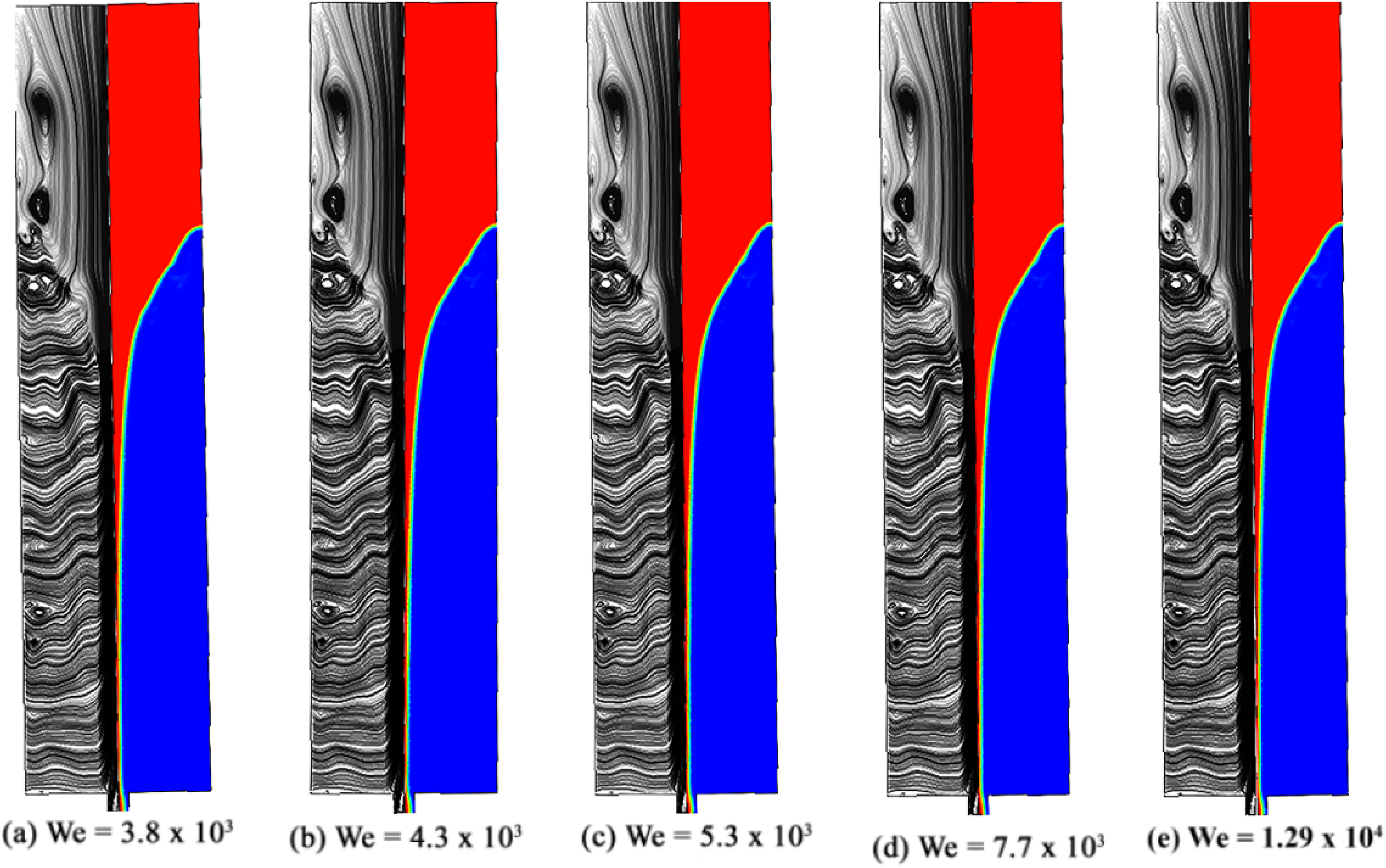
Streamlines merged with volume fraction contours for various We values at the instant of critical height formation.
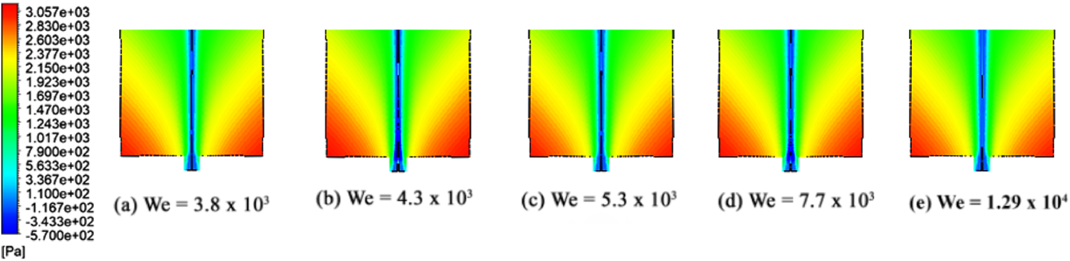
Pressure contours for various We values at the instant of critical height formation.
These observations found in Figures 7, 9 and 11 introduce a new dimension to the understanding of vortex dynamics, as previous studies have primarily focused only on the radial expansion of waterborne Taylor vortices. The present findings on airborne, interfacial, and waterborne Taylor vortex structures provide additional insight into the mechanisms influencing air-core vortex evolution under simplified draining conditions. However, it should be noted as a limitation of the present study that the investigated configuration does not reproduce the complete hydrodynamic complexity associated with industrial continuous casting molds, where the flow behavior is additionally influenced by SEN jet flow, asymmetric flow instabilities, argon gas injection, electromagnetic braking, turbulence-induced multiphase interactions, and slag–metal interfacial effects. Therefore, the present findings should be interpreted as a fundamental hydrodynamic investigation of vortex evolution mechanisms, with only indirect relevance to metallurgical and metal casting systems.
Effect of dimensionless numbers in pre-critical height regime
In the pre-critical regime, air core development is observed from its initial dimple state to a fully formed vortex. As shown in Figure 13, for time instances measured from the start of draining (t) less than 4 s, the air core is in the developing stage (Figure 13(a) to (c)). At t = 4 s, the critical height is reached (Figure 13 (d)), where the vortex just touches the drain port; this elapsed time is referred to as the critical time (tc). During this phase (0 < t < tc), the air core is not fully formed, and the liquid drains out with no vortex interference. Since the drain port is free from the fully developed air-core vortex, it would be expected that the draining process remains unaffected by this partially grown vortex. However, contrary to this assumption, Prabhu et al. 20 observed that even a partially developed air-core vortex can influence the draining process, despite the absence of a direct interaction with the drain port. The exact flow physics underlying this phenomenon was not fully explored in their study. To address this gap, the current study aims to investigate and elucidate how a partially grown vortex affects the draining process.
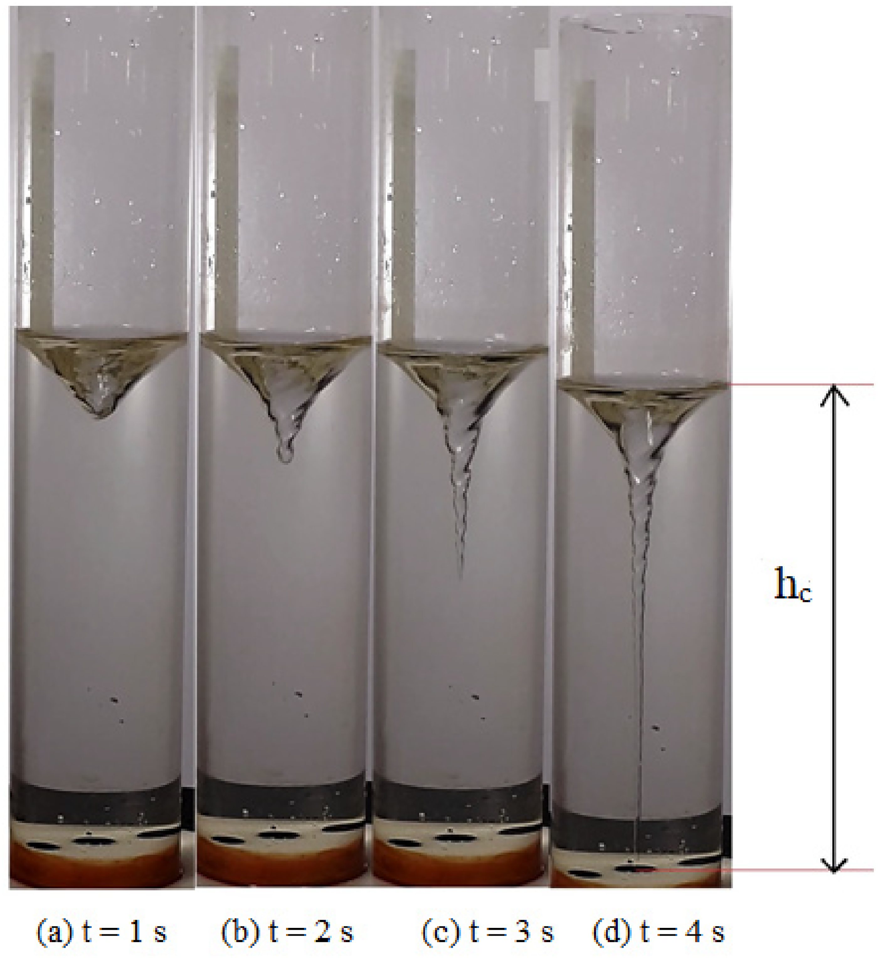
Development of air core from its dimple stage to a fully grown vortex.
It should be specifically noted that for a partially grown vortex, as illustrated in Figure 13, determining the characteristic volume (Vch) becomes challenging due to its definition. The parameter Vch is effective in quantifying the strength of the air core only when the vortex is fully developed and exhibits a straight profile configuration. However, since the vortex in pre-critical height regime is still partially developed, the current study is unable to use Vch to measure its strength. Instead, the study adopts an alternative parameter proposed by Prabhu et al., 7 namely the non-dimensional recession velocity (Vr) in the pre-critical regime. This parameter is better suited for analyzing the dynamics of partially grown air-cores in this phase.
The time-averaged recession velocity in the pre-critical regime (vr = (hi-hc)/tc)) is the velocity with which is free surface of the liquid recedes along the lateral surface of a draining cylinder. This is normalized with the time-averaged recession velocity in the case of complete draining without rotation (vro = hi/to). Equation 10 provides the expression for non-dimensional recession velocity before the critical height formation (Vr). In equation (10), time needed to completely empty the tank without rotation (t0) can be obtained from the continuity equation, and the same is provided in equation (11).
53
In equation (11), the discharge coefficient (ε) is due to the formation of vena contracta and friction between the draining fluid and lateral inner surface of the cylinder. Approximate value of discharge coefficient (ε) is obtained from literature
48
as 0.98.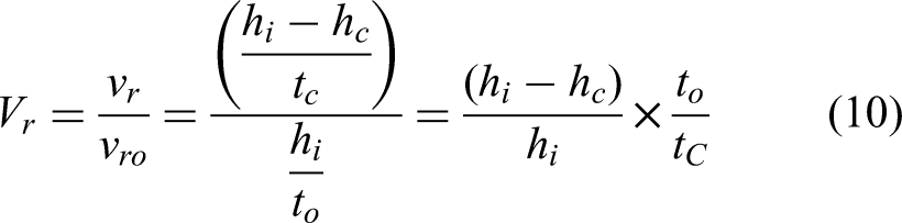
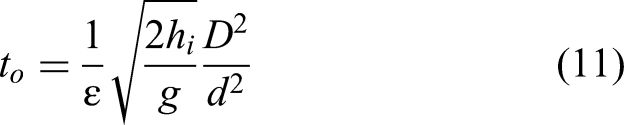
The variations of recession velocity with Froude number (Fr) and Reynolds number (Re) are shown in Figures 14 and 15, respectively. As the air core intensifies, it increases blockage at the drain port, reducing the discharge rate and consequently lowering the efflux velocity. When draining velocity is reduced, recession velocity also declines and thus reduction in recession velocity effectively represents the strength of the air-core vortex. During the pre-critical height period, when the air core does not obstruct the drain port, it is generally expected that the draining process would remain unaffected by the air core. However, contrary to this expectation, the non-dimensional recession velocity exhibits noticeable variations as a function of Fr and Re. The reasons behind this unexpected behavior are analyzed and discussed in this section.
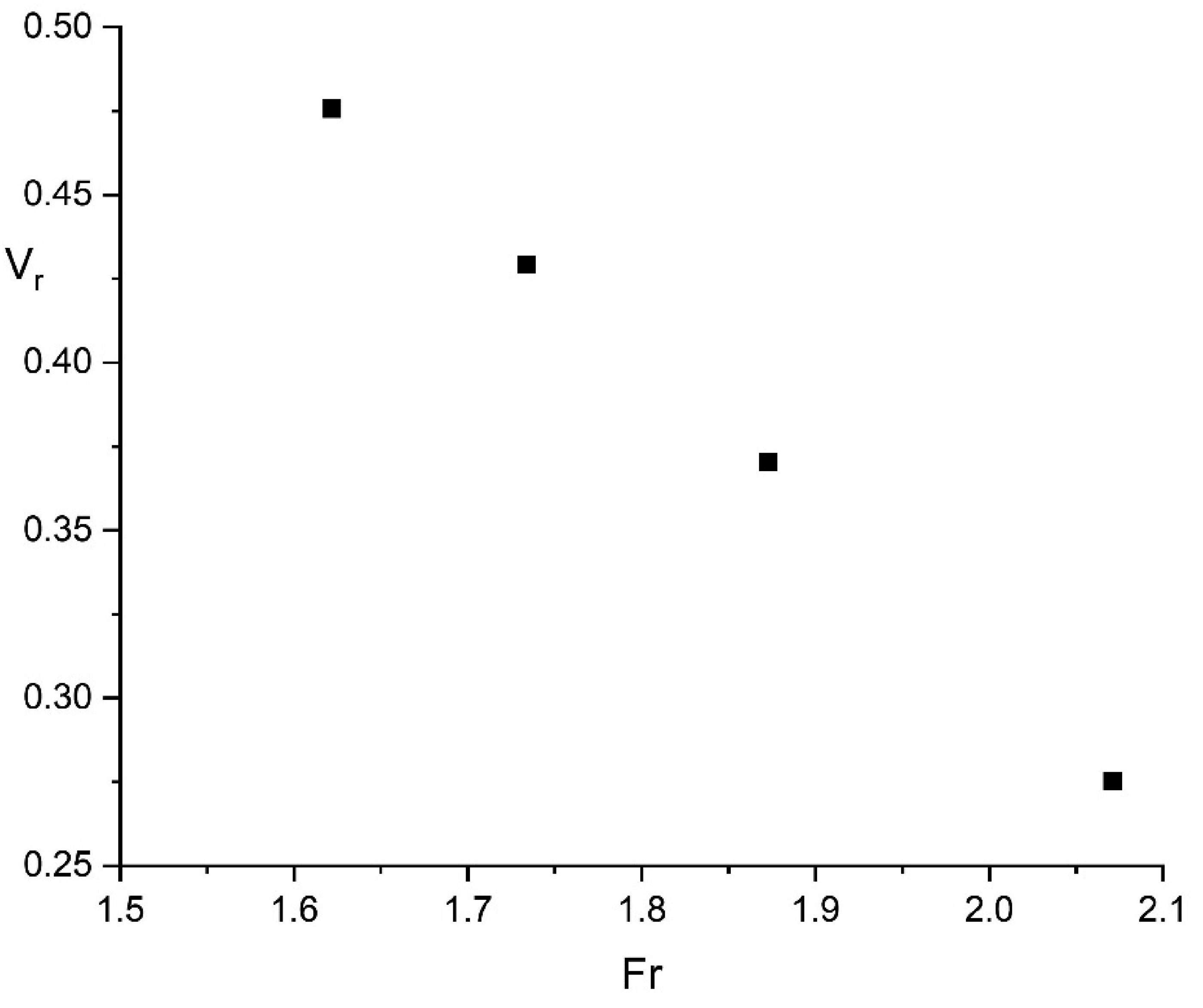
Variation of recession velocity with Fr.
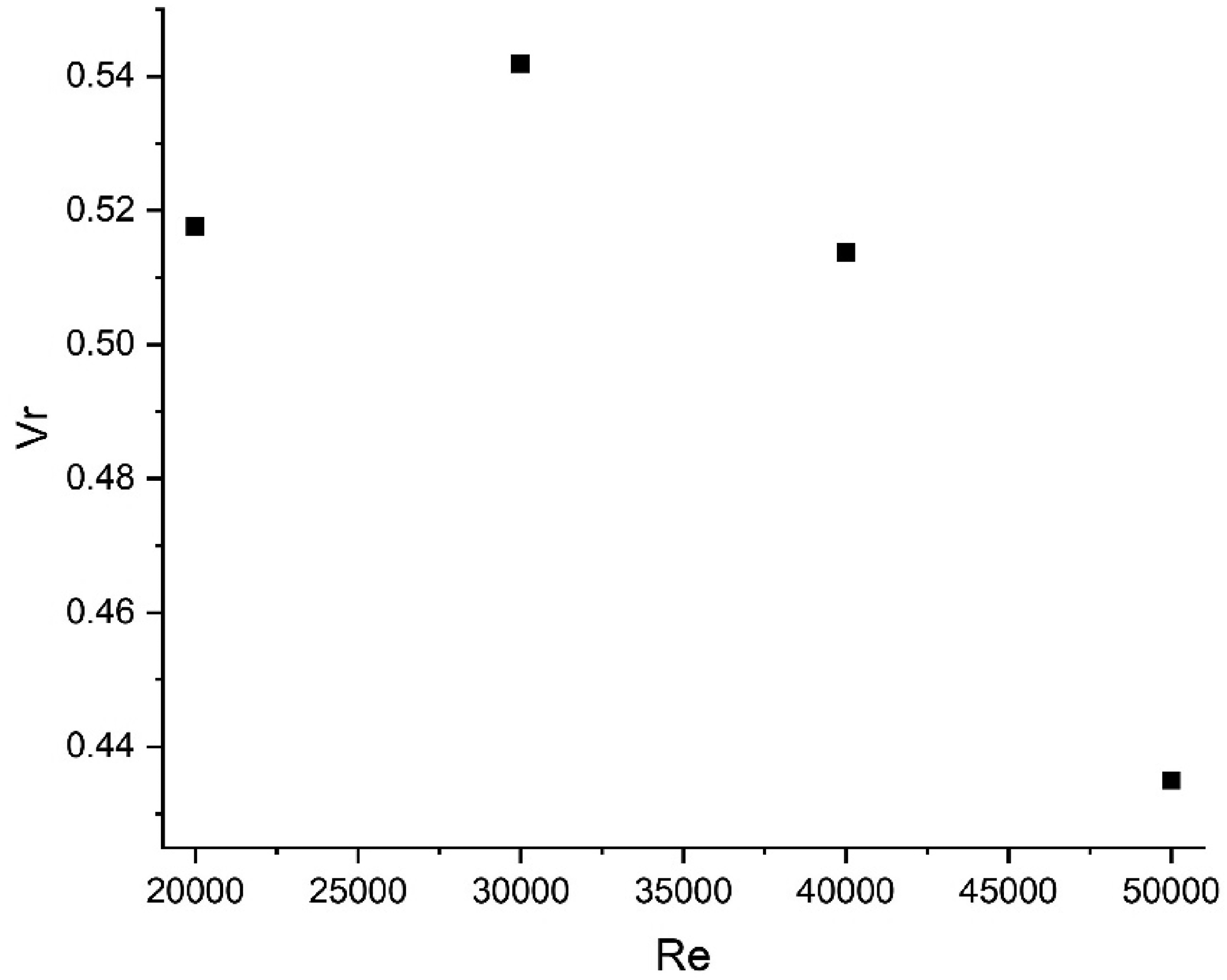
Variation of recession velocity with Re.
It can be observed from Figures 14 and 15 that the non-dimensional recession velocity (Vr) decreases with increasing Froude number (Fr) and exhibits an initial increase followed by a continuous decrease with increasing Reynolds number (Re). This trend in Vr indicates an enhancement of the air-core vortex at higher values of Fr and Re. To better understand the reasons behind this parametric trend, streamlines combined with volume fraction contours at 3 s after the commencemnt of draining, for certain relevant values of these dimensionless quantities are presented in Figures 16 and 17.
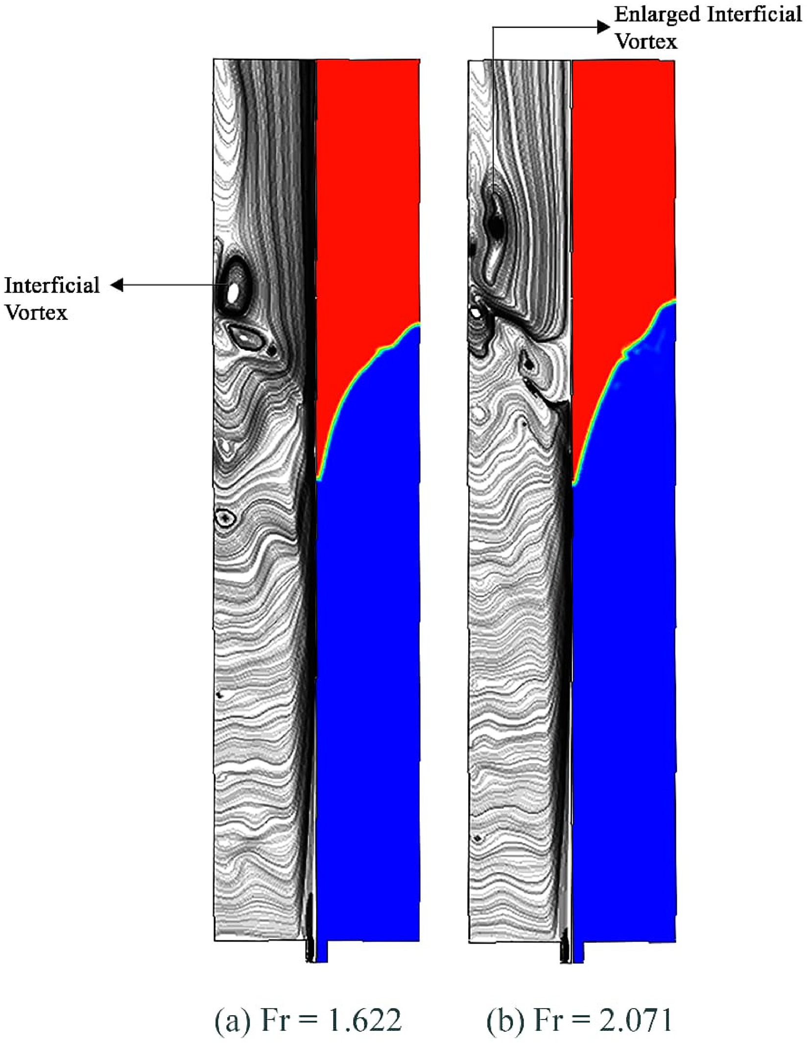
Streamlines merged with volume fraction contours for (a) Fr = 1.62 (b) Fr = 2.07.
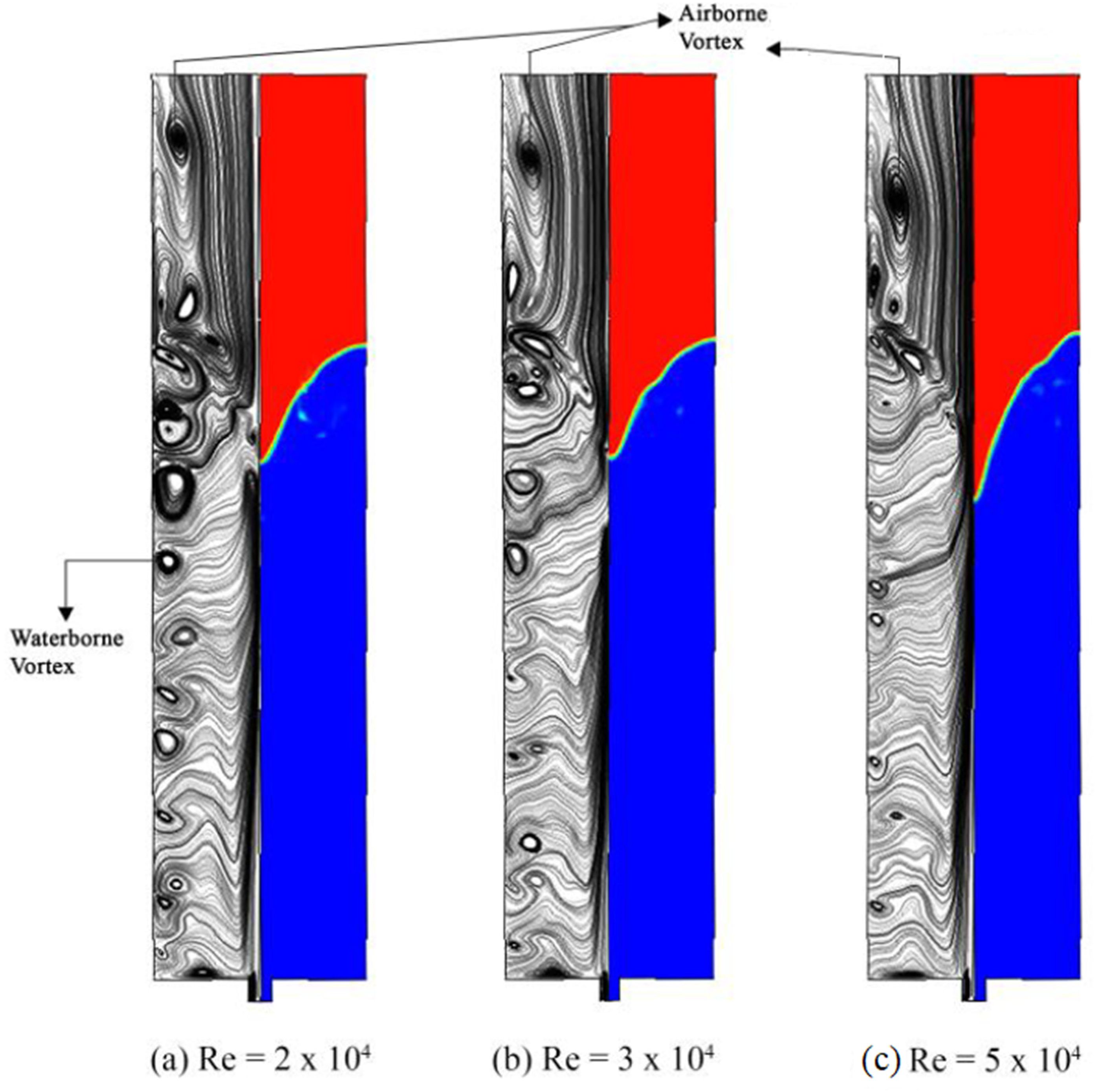
Streamlines merged with volume fraction contours for (a) Re = 2 × 10⁴, (b) Re = 3 × 10⁴, (c) Re = 5 × 10⁴.
It can be observed from Figure 16 that no waterborne Taylor vortex is present in the pre-critical regime, consistent with the observations from Figure 7. Furthermore, as the Froude number (Fr) increases from 1.62 to 2.07, the interfacial Taylor vortex grows in size. This growth strengthens the air core vortex, further lowering the pressure at the drain port, as stronger vortices inherently create low-pressure zones. As a result, more air is drawn in from the ambient environment due to the increased pressure difference between the ambient pressure and the drain port pressure (suction). The increased air ingestion might have dissipated a part of the available head (energy per unit weight) for draining, resulting in a reduction in the recession velocity. This dissipation of available head is visualized as swirl loss by previous investigators. 17 For other intermediate values of the Froude number (Fr), similar observations are noted and are therefore not discussed here.
It is interesting to note from Figure 17(a) that at a lower Reynolds number (Re = 2 × 10⁴), the draining process is governed by both airborne and water-borne Taylor vortices. As the Reynolds number increases from Re = 2 × 10⁴ to 3 × 10⁴, the water-borne Taylor vortex weakens (Figure 17(b), and consistent with the observations of Sohn et al., 50 vortexing is expected to be suppressed. This explains the initial enhancement in the recession velocity (Vr) observed in Figure 15. At higher Reynolds numbers (Re = 5 × 10⁴), however, the trend reverses, and vortexing intensifies, as evidenced by the reduction in Vr shown in Figure 15. The reason for this behavior is explained as follows. As indicated in Figure 17, in addition to the water-borne Taylor vortex, airborne Taylor vortex also plays a significant role in controlling the strength of the air core at higher Reynolds numbers. In the high-Re regime (Re = 5 × 10⁴), as indicated by Figure 17(c), the airborne Taylor vortex intensifies and shifts in the negative axial direction (towards the drain port), leading to a further reduction in pressure (more negative) at the drain port and thereby increasing air ingestion into the air core. As discussed earlier, this increased air ingestion possibly dissipates a portion of the available head, resulting in a reduction in the recession velocity.
The findings presented in Figures 16 and 17 offer a fresh perspective on the dynamics of vortex formation, significantly advancing our understanding of the phenomenon. While previous research investigations have predominantly focused on the effects of air-core vortexing during the overall draining process, the present study reveals—what has not been addressed by earlier investigators—that the pre-critical height regime also plays a crucial role in shaping vortex behavior. To particularly highlight, the current results provide deeper insights into the mechanisms driving air-core vortex formations, which have significant implications in various engineering processes, especially in continuous casting of metals. This novel understanding opens up potential strategies for better controlling vortex formation, particularly in metal casting systems, where such vortices can greatly affect the quality and integrity of final products.
Conclusions
The present study provides a detailed examination of air-core vortexing phenomenon occurring during liquid draining from cylindrical tanks, with a focus on the influence of key dimensionless numbers—Froude number (Fr) and Reynolds number (Re) on this phenomenon. Using the characteristic volume of the air core (Vch) as the primary metric for vortex strength, this study has made novel contributions to the understanding of vortex dynamics. Notably, the current study demonstrates the existence of airborne Taylor vortices for the first time, their axial expansion, and their significant role in modifying the vortex strength. This is a critical insight, distinguishing the current work from previous literature, which focused primarily on radial expansion of waterborne Taylor vortices. Additionally, the study challenges the conventional notion that partially developed air-core vortices have no effect on the draining process by showing that the recession velocity is influenced by changes in Fr and Re even in the pre-critical height regime.
The results of the current study have significant implications in metal casting processes, where controlling vortex formation can mitigate undesirable vortex effects, thereby significantly improving the quality of the casted metal products. However, it should be noted as a limitation of the present investigation that the adopted axisymmetric draining configuration does not reproduce the complete hydrodynamic complexity associated with industrial continuous casting molds. Therefore, the findings of the present study should be interpreted as a fundamental hydrodynamic investigation with indirect relevance to industrial casting systems. Nevertheless, the findings of the present investigation offer valuable insights into controlling and optimizing vortexing behavior in industrial applications, opening avenues for further exploration and refinement of vortex suppression strategies.
Footnotes

Funding
The authors received no financial support for the research, authorship, and/or publication of this article.
Declaration of conflicting interests
The authors declared no potential conflicts of interest with respect to the research, authorship, and/or publication of this article.