
Abstract
Given the ever-growing need for robotics learning, an experimental teaching model was developed in combination with virtual reality, remote control and an on-site laboratory to support robotic kinematics teaching. Based on the Browser/Server mode, a kinematics simulation platform of a 6-DOF articulated robot and a 4-DOF SCARA robot was established. Furthermore, a Client/Server mode SCARA robot’s remote-control system was developed along with a simulation with the same functionality and interface. Experiments with virtual reality simulation can eliminate the safety concerns associated with real-world robot operations. Test resources can be web-shared for wider audiences. Remote-controlled experiments could operate the robot off-site and achieve the same results as on-site operations. Virtual reality and remote-controlled experiments could also alleviate the shortages of lab time, space, equipment, staff and teaching time. Students could choose one of the three modes to examine the effectiveness of their study, or they could first use simulations and later operate robots on-site or remotely and obtain real-world experimental results. The various testing combinations available to learners would improve the flexibility, effectiveness and safety of experiments and would meet various learners’ needs.
Introduction
China has become the largest global market for industrial robots and urgently needs robotics professionals. Universities and technology schools have expanded their robotics training and education, such as by offering more robotics classes and adding new robotics majors or departments. Kinematic control of robotic manipulators is one of the core subject areas for robotics. This control includes mechanics, forward and inverse kinematic model, path planning, trajectory interpolation and collision-free algorithm. Applying theoretically learned knowledge for actual robotic operation is an important practical requirement for students. Owing to the high cost of robots, it is difficult to purchase sufficient equipment to meet growing teaching needs. Furthermore, improper operation could easily cause damage to the robots and accidents to personnel. Concurrently, university laboratories usually face a shortage of lab time, space and staff.
To resolve the above issues effectively, based on our traditional on-site lab practice, this study explored robot virtual reality (VR) experimental simulation and robot remote-controlled experiments having web-based access.
VR experiments use software that imitates real experiments on real infrastructure without any restrictions of cost, space, time and schedule. Remote control (RC) experiments are a remote means of performing real physical experiments, which enables the setup of equipment and continuous communication with students and provides real experimental data to students conducting experiments inexpensively. Compared with hands-on laboratories, the students access remote experiments over the internet. Fewer people are required to administer laboratories for large student population; students have more flexibility to arrange their experimental timetable.
Depending on students’ needs or course requirements, three types of VR experimental simulation, remote-controlled experiments, and on-site experiments can be conducted independently or as a combination of any two or three of them. The experiments could proceed from virtual online to reality. Students could first finish tests on the virtual platform and later move to actual laboratory operations or web-based remote-controlled operations. This new teaching methodology could improve equipment usage efficiency and safety, reduce students’ stress and inspire in them the spirit of exploration.
Related works
Robot virtual experimental simulation platform
Currently, there are several studies on robotic simulation platforms, with the following four solutions
Robotic simulation software:
Such software as ROBCAD, 1 USARSim, 2 Webots, 3 Simbad, 4 Workspace, 5 MRDS 6 and others 7 can design robotic models quickly and simulate real kinematics, possess realistic 3D effects and can control the robots through script programs. However, these software packages have certain weaknesses: they are expensive, are not open source, or are highly difficult to develop; therefore, their applications are highly restricted.
In addition, robot manufacturing companies have developed simulation platforms, such as ABB RobotStudio.
8
In this study, the simulation objects are only limited to each company's specific robots. Their interface and functionality are not designed to meet a customer's special needs.
2. Software with professional kinematics and dynamics analysis:
ADAMS, MATLAB and others fall into this category. ADAMS/View
9
can set up a robotic visualization model and simulate system kinematic and dynamics characteristics in real environments. Being a commercial software, ADAMS has many limitations. Its underlying algorithm is not open source and its embedding algorithm is difficult to implement.
10
MATLAB11,12 has high computing power. Its Simulink toolbox can build models, simulate and analyze a dynamic system. Additionally, its Simulink/Robotics toolbox can provide several very important modeling and simulation functions in robotics, which are very easy to use. However, MATLAB and its related toolboxes have weak 3D displays, low operating efficiency and poor algorithm code portability.
13
In some studies,14,15 MATLAB and ADAMS have been integrated.
3. Integration of 3D modeling software and other programming tools:
3D modeling software such as SolidWorks,16–19 Pro/E
13
and VR languages such as VRML
20
and Unity3D
21
have very powerful 3D modeling capabilities. Combined with programming languages such as MATLAB,13,16,20 C++,
17
C#,
18
LabVIEW
19
and Python,
21
they can establish experimental simulation platforms, set up flexible user interfaces and implement various functionalities.
4. Software development based on graphic databases such as Open Graphics Library (OpenGL) and Web Graphics Library (WebGL):
As a cross-platform graphic interface, OpenGL10,22–25 can present 3D graphics without third-party software or plug-ins; therefore, a simulation platform developed on OpenGL could solve the above problem suitably. However, OpenGL cannot run as a web-based application. WebGL26–28 can create web-based 3D graphics using JavaScript, which is embedded into an internet browser without installing other software or plug-ins.
Table 1 lists examples of robotic simulation programs.
Examples of robot simulation programs.
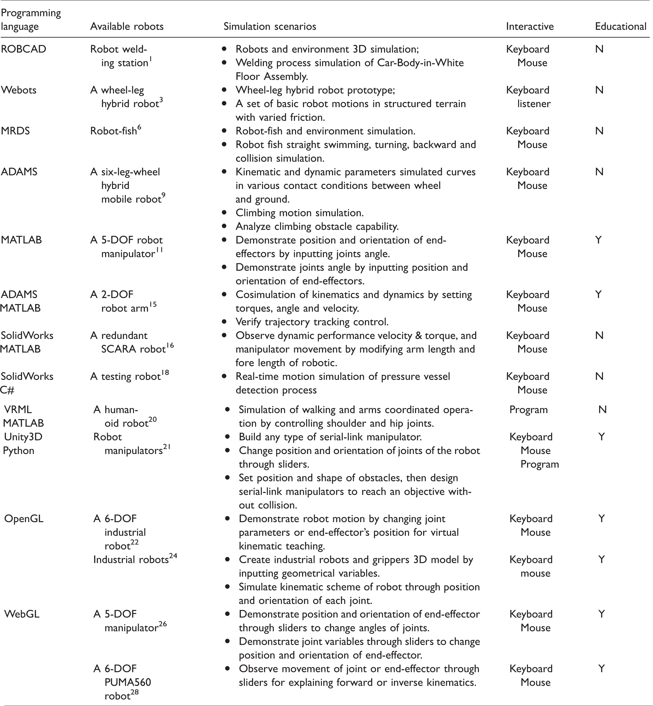
Most applications of robot virtual simulation1–10,13,14,16–20,25 are designed for academic or engineering purposes (there are several similar studies that are not listed in this paper). In educational applications,2,11,12,15,22–24,26–28 the robotic models have been established by developers and the learners just observe the motion of end-effectors or joints using a keyboard and/or mouse. These simulations are almost for demonstration of the basic kinematics or dynamics knowledge. In the simulated platform, 21 the programming in Unity3D is for teachers who provide the student files describing the environment of the robot and the robotic tasks. The students use a built-in algorithm to try various robot configurations to find an obstacle-free path to the final position via keyboard and mouse. Although obstacles are introduced, no collision-free method is involved.
Robot remote-controlled platform
With the development of robotics and network technology, robotic RC has been developed and applied in important areas, such as space exploration, underwater operations, dangerous environment operations and web-based medicine. This technology has considerable advantages in terms of laboratory space, the safety of operators and users sharing devices in different locations. This technology has also been used in robotics teaching.
Several studies29–31 provide practical examples of applying RC on robotics teaching. Lai et al. 29 used the Browser/Server (B/S) architecture model with three layers for RC and remote supervision. The user can control the remote arm robot and observe effects in various control algorithms and parameters. Lopes et al. 30 proposed a remote laboratory for robotics that allows experiments with a mobile robot to be performed, tested and validated remotely. Students can control and manipulate the robot with simple commands, or use the C/C++ programming language to develop complex programs. Radhamani et al. 31 developed a remotely controlled robotics labs as a new pedagogy for augmenting laboratory education. Feedback analysis among students suggested the use of an online-based bioinspired robotics labs in augmenting the conceptual knowledge of working with a robotic arm, forward and inverse kinematics and studying artificial neural network patterns beyond classroom hours.
Shen 32 developed a 3D simulation and RC software based on Client/Server (C/S) structure software for a 5-DOF education robot. The simulation control software can take the place of a conventional teach pendant unit. Safaric et al. 33 integrated remote hands-on experiments into control and/or robotics courses to minimize the gap between theory and practice, teach students the use of remote rapid control prototyping and decrease educational costs. Another study 34 proposed the development of a low-cost educational framework for the RC of a PUMA robot, which is divided into two parts: the PUMA support platform provides basic control and monitoring functions to remote users that are connected to the internet via a local computer; the additional modules include on-line programming, off-line programming and simulation. An RLab 35 is developed that provides students with online access to the real-world hardware for remote experimentation, and a VLab 36 is also developed to simulate robot activity in a nonimmersive VR environment before execution on the actual device.
Other works29–31 effectively solved the issues of teaching resource sharing and distance learning. However, these methods directly control real robots; thus, any mistakes in control algorithms or operations could damage the robotic equipment. Some studies32–36 have added robotic 3D virtual simulation into an RC system. Compared to operating directly on real robots, remote-controlled operation with 3D simulation could considerably improve the safety and practicality of robotic teaching. However, the two systems are totally separate in the above studies, which results in users taking more time for different interactions, operations and actions.
Robotic kinematic experiment platform based on B/S
Introduction to the platform
SCARA and 6-DOF articulated robots are widely used in industrial applications. Our platform selected a 4-DOF GOOGOL GRB 3014 SCARA robot and a 6-DOF ABB IRB 120 robot as simulation targets.
A B/S pattern is developed to share resources of experimental education among a broader student audience, and WebGL technology is used to build a 3D model that would make effective realization of the network sharing possible. The students can access the experiment platform through internet anytime from anywhere. Meanwhile, multiple control modes are developed. In addition to the simplest demonstration of robot motion, the students need to set up the kinematics model of certain types of robots by themselves and write algorithms based on robotic tasks in familiar programming languages to control robot activity, so they can validate the effectiveness of their method in the platform.
The functionalities of the robotic kinematic experiment platform are as follows:
Observing robots’ structural synthesis and motions by parameters; Robot end-effector position and orientation control; Robot trajectory planning; Collision avoidance path planning among robots and obstacles (static or dynamic); Coordination of dual robots under complex environments.
Platform design
Robotic kinematic simulation platform consists of four modules: motion control, motion status display, obstacles or operational targets generation and VR simulation. Among them, the motion control module includes three control modes of shortcut commands control, robot programming language control and interpolation points control. The motion control module realizes robotic or target motion planning in VR simulation module. Furthermore, this module could also calculate the real-time status information for the motion display module and the robot end-effector trajectory for the VR module. In the environments of robot workspace, there will be operating objects and obstacles, namely, the target collectively referred to herein, which may be stationary or moving. The target generation module supplies obstacles or operation objects for the VR simulation module. The motion status display module provides real-time dynamic information of robots for each axis. The virtual simulation module shows the 3D working environment, the robot's movement and its end-effector trajectories.
Figure 1 shows the relationship between the modules and the developing method.
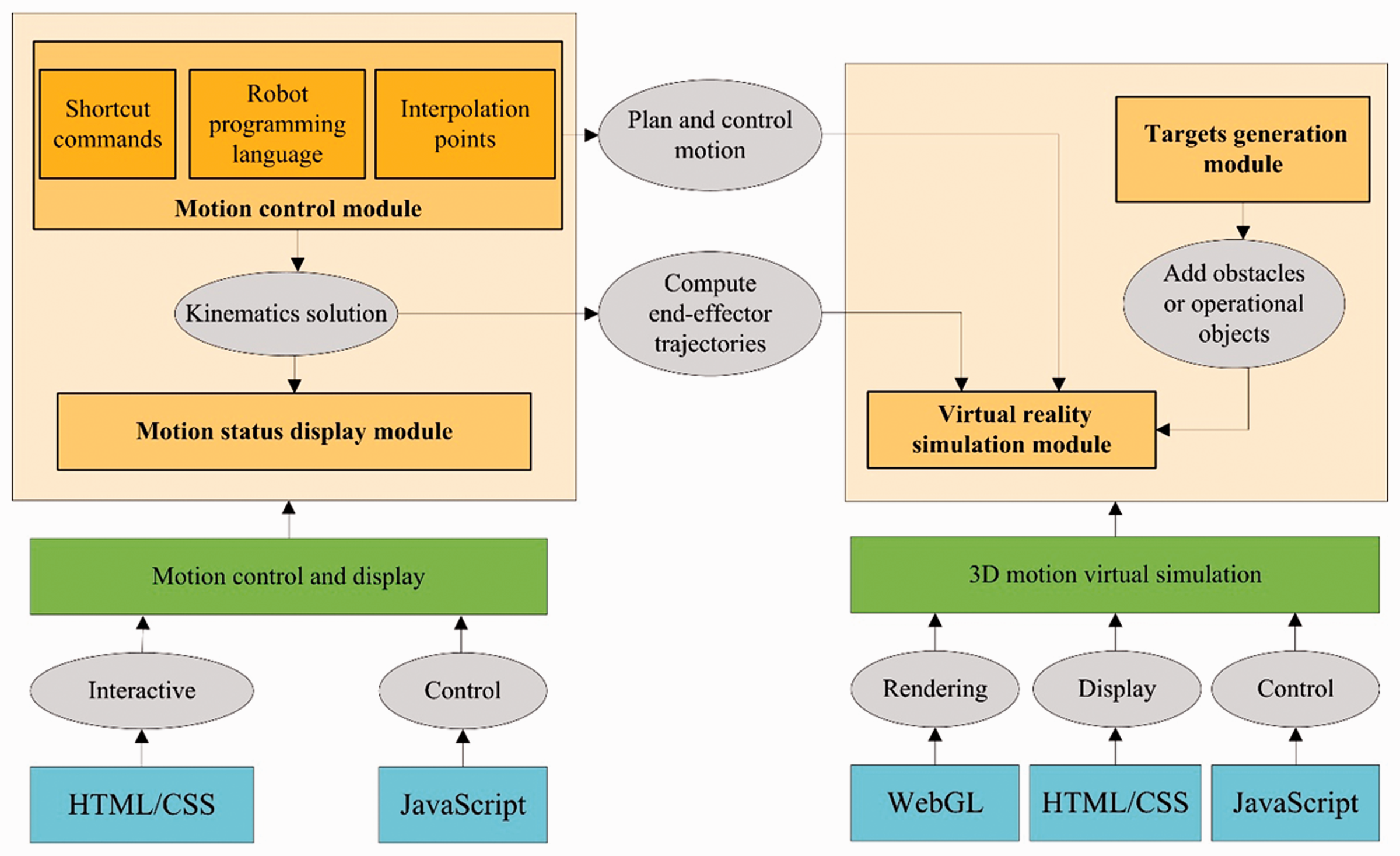
Module structure and realization of simulation platform.
Motion control and display have been mostly implemented using Hyper Text Markup Language (HTML), Cascading Style Sheets (CSS) and JavaScript. HTML/CSS is used to create Human Machine Interface (HMI); JavaScript is used to implement motion control. 3D motion simulation is mostly carried out by HTML, CSS, JavaScript and WebGL graphics database. Among them, WebGL graphics database provides 3D motion simulation module rendering; HTML and CSS provides control display; the JavaScript language is mostly responsible for controlling the behavior of each entity in the 3D motion simulation module.
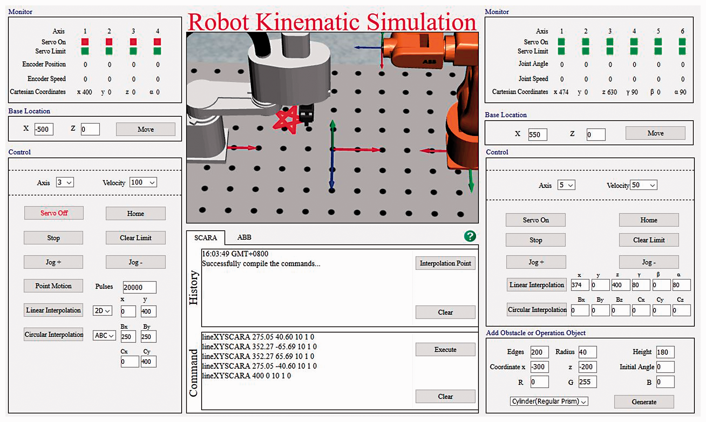
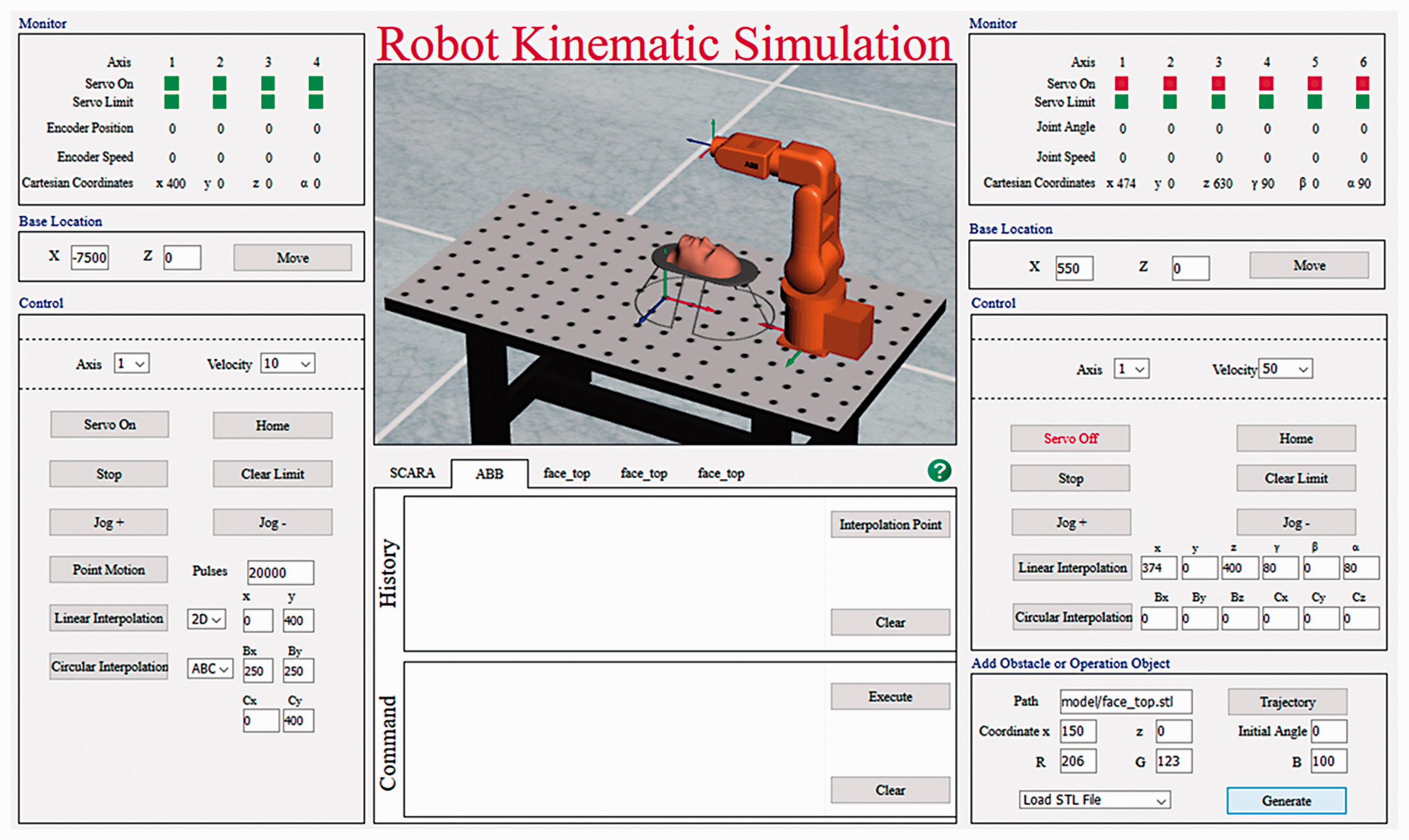
The HMI of the robot kinematics simulation platform is shown in Figure 2. It consists of: ① motion simulation display window; ② targets generation panel; ③ motion status display panel; ④ shortcut commands panel; ⑤ code editor; ⑥ robot position adjustment panel and ⑦ Help.
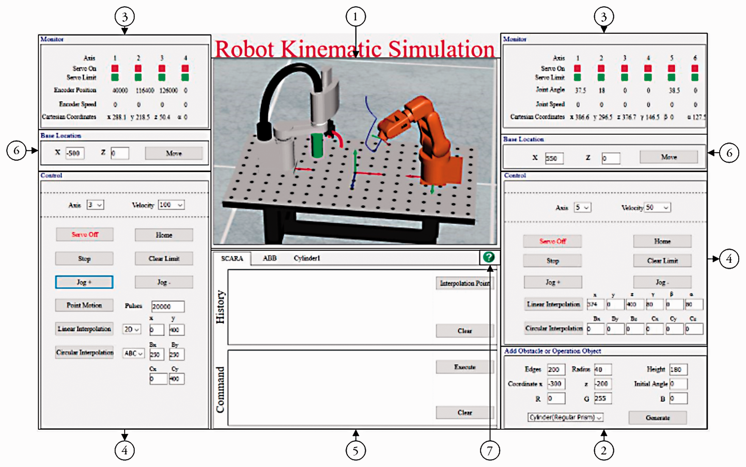
Human Machine Interface (HMI) of robot kinematics simulation platform.
The simulation experiment platform has the following characteristics:
In the simulation window, one or two robots can be selected and displayed. Their position is adjustable. A target with regular shape can be generated by setting. Models with complex shape can be imported; A single robot can be controlled independently, and two robots can be controlled to move at the same time. The movement of the target can be controlled through programming; In the simulation window, all objects can be viewed from various directions and sizes. Robotic motion status and the end-effector movement trajectories can be viewed in real-time from the simulation window. Three robotic motion control methods are provided including shortcut commands, robot programming language and interpolation points. The autonomous research algorithm can be tested and analyzed. Software is open and scalable.
Interactive design
Coordinate systems in simulation window
As shown in Figure 3, there are four coordinate systems in the simulation window. According to the D-H coordinate system generally used in robotics, the base coordinate system of the SCARA and the ABB robot are separately established as
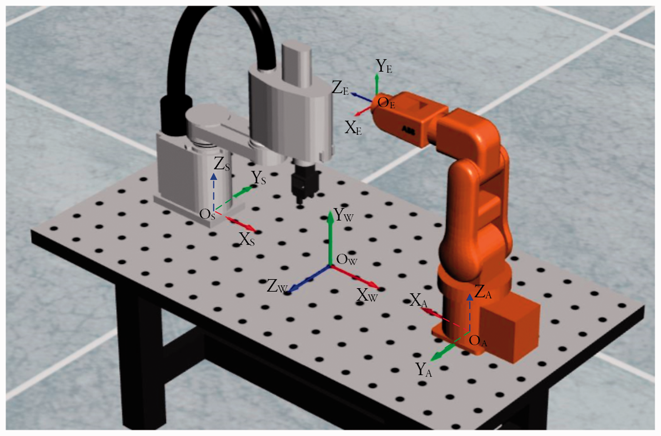
Coordinate systems in simulation window.
The homogeneous transformation matrix from 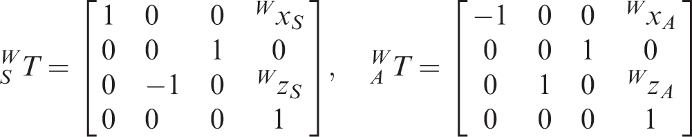
The homogeneous transformation matrix 
Motion simulation
As shown in Figure 2, the movement of the robot and the target can be observed in real-time in the simulation window. In the HMI, the end-effector trajectory of the SCARA robot is shown in red as a thick curve, while the ABB robot is blue and is a thin curve.
The real-time movement status of each joint of the robot can be displayed on the movement status display panel where it is located, as shown in section ③ in Figure 2. The first line of the panel indicates the servo-enabled status of each axis of the robot. Red indicates that the servo motor has been powered on, while green indicates that the servo motor is off. The second line indicates the limit of each joint. Red shows robot in a limit position now, while green shows robot in its working area. The third line shows the positions of joints for the robot. The SCARA robot in the left uses the number of encoder pulses as the unit, and the ABB robot in the right uses the angle (°) as the unit, which are the same as their actual application. The fourth line shows the movement speed of each joint.
When the cursor is in the simulation window, scrolling the middle button can scale the scene. Pressing and holding the middle button can rotate the scene to change the viewing angle. Figure 4 shows the rotation and magnification of the simulation scene.
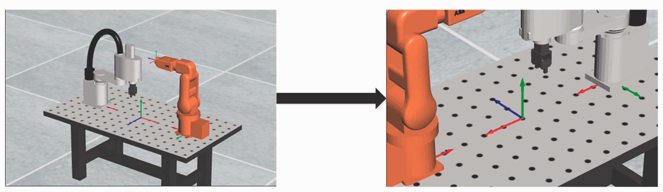
Rotation and magnification of the simulation scene.
Motion control
Shortcut command control
The shortcut command control panel of the SCARA robot and the ABB robot is shown as in section ④ in Figure 2. The “Servo On/Off”, “Home”, “Stop” and “Clear Limit” buttons control, respectively, the robot servo control on/off, the robot return to the initial position, the robot stop motion and clearing the robot limit alarm.
To observe the robot movement, the program sets up the robots “Jog +”, “Jog −”, “Point Motion” for each joint and “Linear Interpolation” and “Circular Interpolation” for robot end-effector.
2. Robot programming language control
Simulating motion control functions from the original manufacturer of the robot, robot programming language control mode can control robot motion as real robots actually do. Under the “Motion Command” control mode in the simulation platform ⑤ area, the commands to control robot or target movements can be entered.
A motion command consists of a command function name and parameters sequence. The command function name and every parameter are separated by spaces. The format of a legal motion command is “command function name (space) parameter 1 (space) parameter 2 (space) paremeter3 ….
In the code editor window, a button is set to switch between two modes: in robot programming language, these are named “Motion Command” and “Interpolation Point”. If it is currently in “Interpolation Point” mode, clicking “Motion Command” switches the mode to “Motion Command” control mode and vice versa.
As shown in Figure 5, robot programming language controls the movement of the SCARA robot, and its trajectory is five-pointed star, visible in red thick line on the monitor.
SCARA robot drawing a five-pointed star by robot programming language.
Figure 6 shows the process of detecting the legitimacy of the command format and compiling the commands. If there are errors in writing the code, an alert should be shown where the error happens. If the format of all commands is correct, the algorithm will compile the command list to the commands in the form of JavaScript, which can be executed to control the motion of the robot or obstacle in the virtual simulation environment.
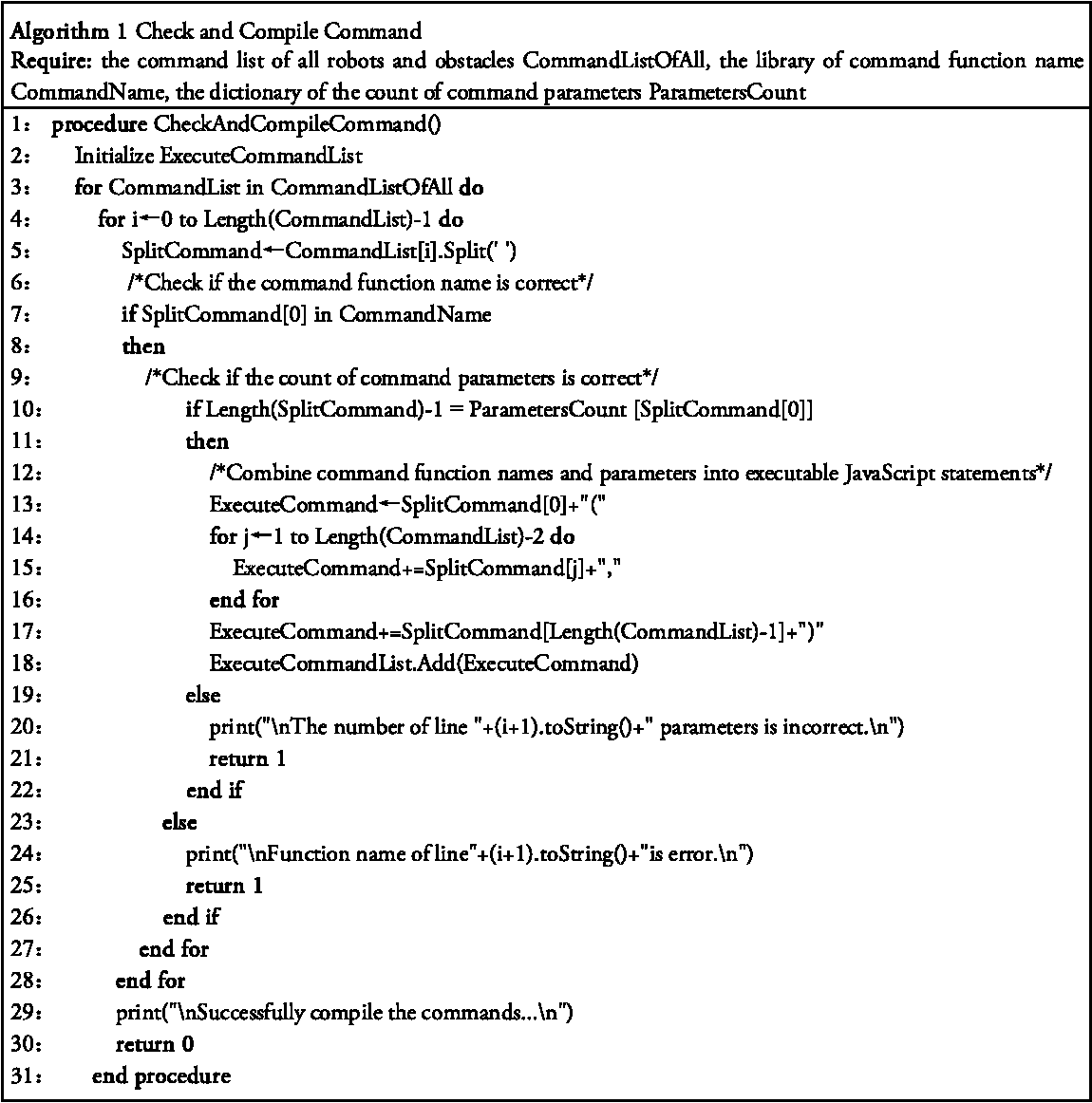
Detect the legitimacy of the command format and compile the commands.
3. Interpolation point control
The robot motion control ultimately involves controlling each joint so that the robot passes through each interpolation point on the trajectory in the proper order. To master and understand the robot motion control method more deeply, the interpolation point mode has been set up. The interpolation point control mode allows users to model and implement algorithms in a familiar programming language (e.g. MATLAB, VB, C++ or LabVIEW) and control the robot following a series of interpolation control instructions, such as ABB robot interpolation point control format “joint angle 1 + space + joint angle 2 + space + joint angle 3 + space + joint angle 4 + space + joint angle 5 + space + joint angle 6”. Figure 7 is the space helix trajectory obtained by the interpolation point control method.
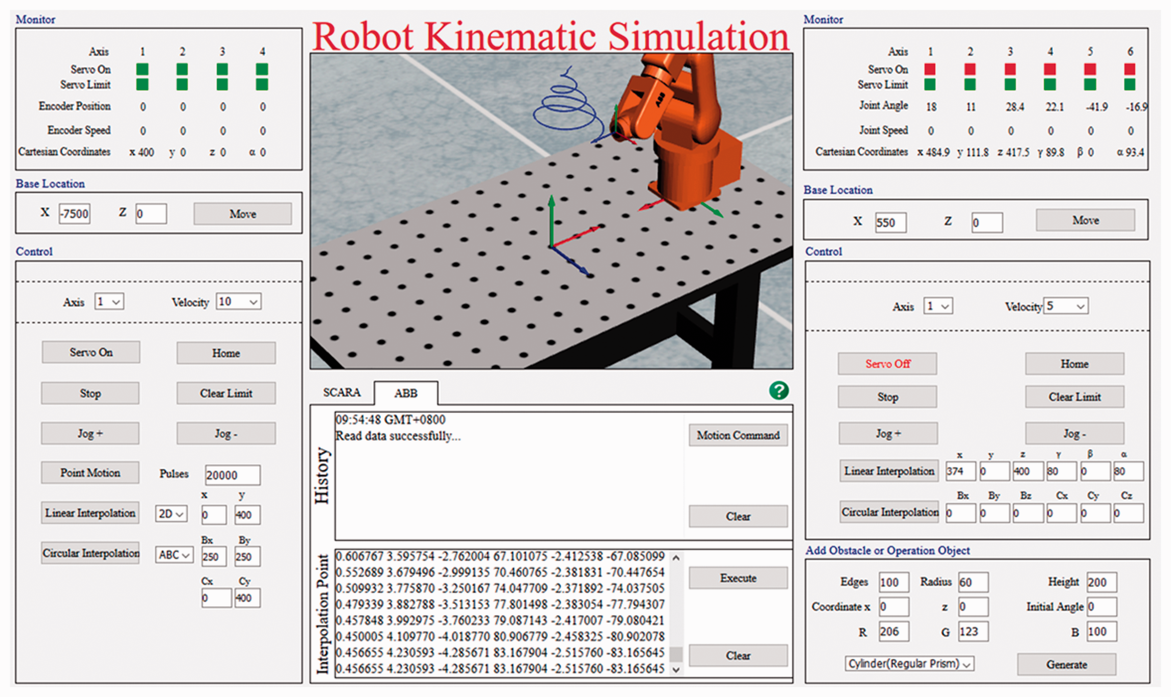
ABB robot drawing a spiral trajectory by interpolation points.
Robot and its working location settings
X and Z values are set in base location of section ⑥ and “move” is clicked, as shown in Figure 2, to change the relative position of the robot base center to the world coordinate system, i.e. to change the position of robot in the workbench. When
Target setting
Target generation 2. Target motion control
In the Settings panel shown in Figure 2 of section ②, the drop-down menu at the bottom left provides the choice of three shapes for cylinders, cones and spheres, as well as the import of the 3D model. “Load STL File” is selected, and the path of the STL file to be imported is input in the “Path” text box. The “Generate” button is clicked to import the STL model into the simulation scenario. The model file point cloud data can be downloaded from the same website. The first line of the panel sets the size of the target body, the second line sets the position of the target body relative to the world coordinate system and the third line sets the color of the target body. A green cylinder object example is shown in Figure 2.
After the target is generated, it appears in the tab of the control window. By clicking on the icon, the user can exercise control in the code editor. Similarly, there are two forms of control, robot programming language and interpolation points.
For example, under “Motion Command”, the instruction “lineObstacle −100 0 400 0 0 0 10” controls the target and moves it from its current position and orientation at 10 mm/s to the target position and orientation of x = −100, y = 0, z = 400, γ = 0, β = 0, α = 0.
Interpolation point control can not only realize the control of an arbitrary trajectory of the target but also control the orientation of each position and the running speed.
As shown in Figure 8, the interpolation points command that control object from x = 0, y = 0, z = 200, γ = 0, β = 0, α = 0 to do circular motion with a radius of 200 mm and point
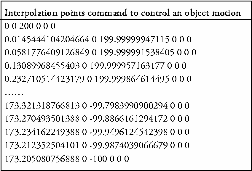
Interpolation points command example.
3. Target deletion
Positioning the cursor to a target body, its operating menu is selected by right-clicking, and then clicking “Delete” deletes the target body.
SCARA robot RC experiment platform
Another SCARA robot RC/virtual simulation teaching platform based on C/S mode is developed that is available to students of some specific majors. The students can control the simulated robots first, the move to real robots in the laboratory after the expected kinematics results are achieved. The client software system takes a Windows system as the development environment, Microsoft Visual Studio 2010 as the software development platform and C# as the software development language. The client HMI is shown in Figure 9 (shown in Chinese). Unlike other designs, the virtual simulation and the RC are integrated into one consistent application. They share a control platform so that students need not spend more time in learning interfaces and functions. The interface design includes the following: ① robot live video in real time; ② robot VR motion simulation; ③ robot end-effector position, joint speed and acceleration curve; ④ robot joints status and motion information ⑤ shortcut command control panel and ⑥ code editor and historical operation records.
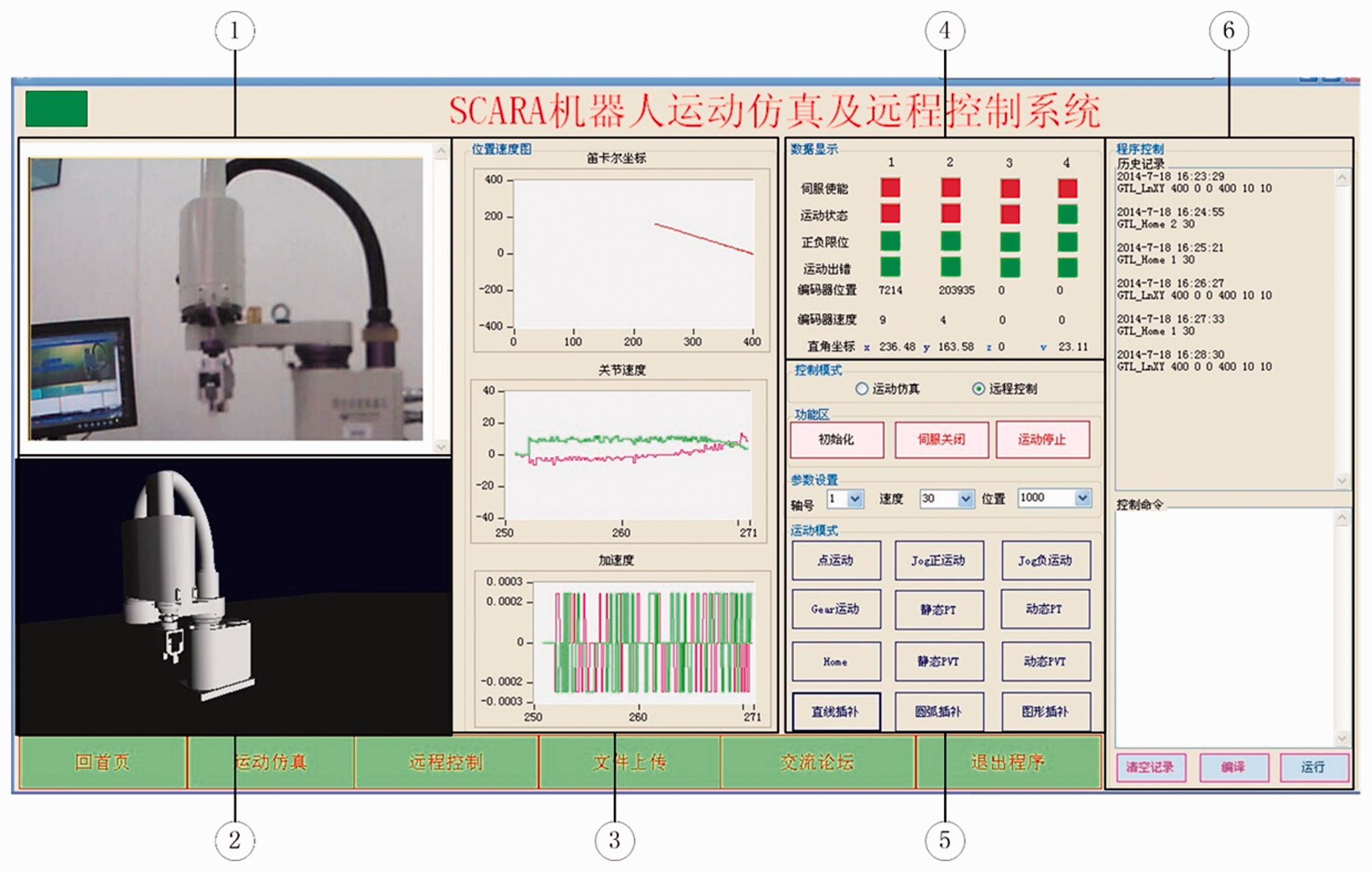
Client interactive interface of SCARA robot remote control and virtual simulation.
RC/virtual simulation experiment teaching system is divided into client layer, service layer and physical layer. The system logical structure and function are shown in Figure 10.
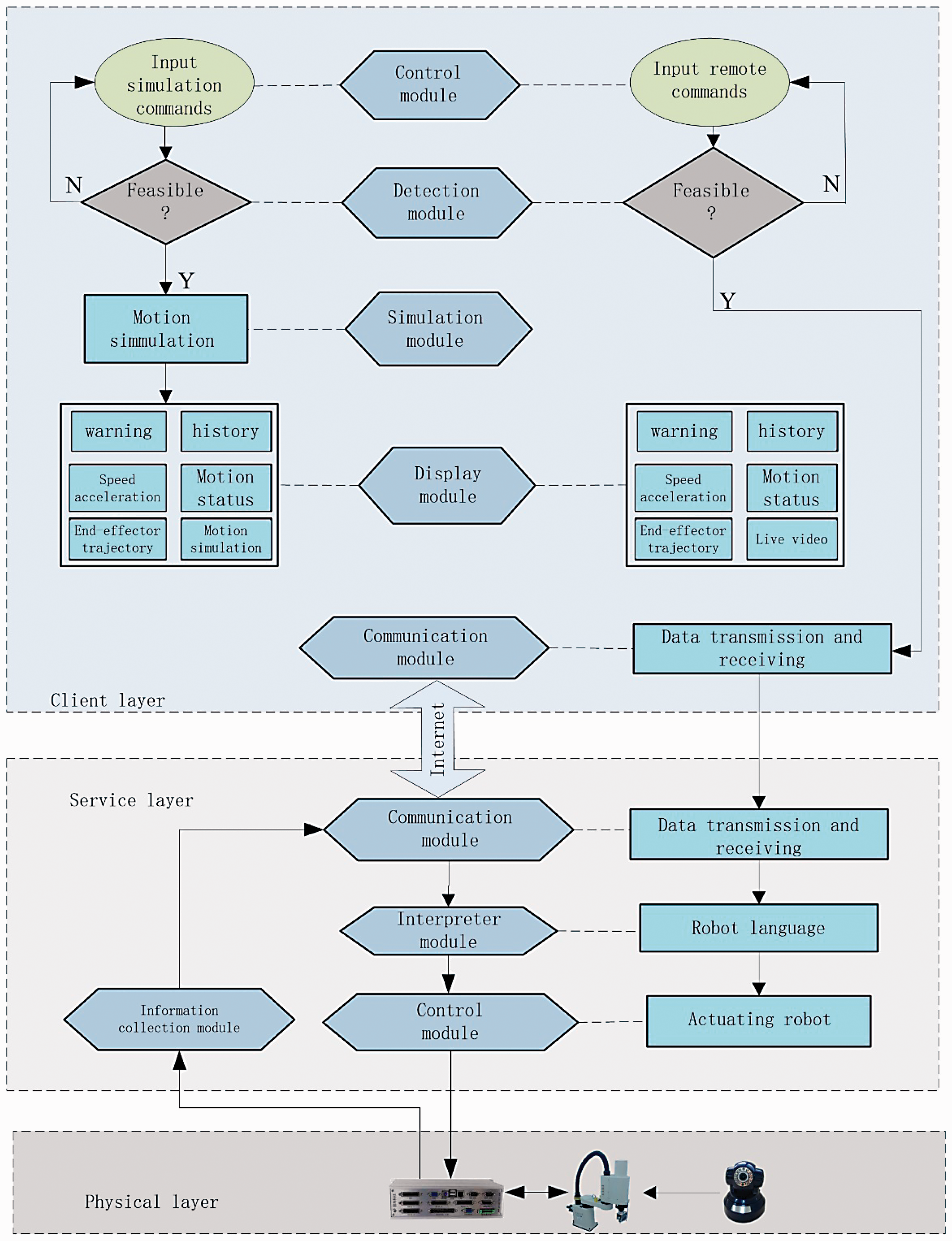
Remote control and virtual simulation experimental teaching system framework.
SCARA robot kinematics simulation based on OpenGL
The client-side control module generates the motion simulation command. The detection module detects whether the command satisfies the current robot behaviors and, if so, sends the command to the simulation module, and the simulation module performs the motion simulation and feeds back the motion state to the display module.
The simulation module adopts OpenGL technology to construct the VR environment, which includes 3D modeling and virtual motion simulation. The virtual control commands or functions are programmed based on the actual motion control library of the robot with the same calling and control effects as the actual robot.
SCARA robot RC based on C/S
The RC system adopts the C/S mode to realize network communication based on WinSock technology of Transmission Control Protocol/Internet Protocol (TCP/IP) protocol. The server establishes the monitoring thread and continuously monitors requests from the client. A connection between client and server is established to achieve two-way data transmission. The server receives the client's control commands and feeds back the robot's motion status to the client.
Control information is passed from the client to the robot. To avoid blocking and losing information in the transmission process, multiple motion control instructions are packaged and sent as a single packet.
The client-side control module generates an RC command. The detection module detects whether the command satisfies the current robot behavior and, if yes, sends the control commands to the client communication module. The client communication module encodes the control commands and then transmits them to the server via the internet. The server communication module receives and decodes the client's remote-control commands, and then the interpreter module converts the decoded commands into an executable robot driver. The server control module drives the robot to realize RC according to the driver executable program.
Remote monitoring status information is obtained and transmitted in real time from the real device. The status display includes robot live video, robot joint servo, limits, position and speed of the encoder, end-effector position and joints speed and acceleration curve.
Applications and evaluation
Applications
The robot virtual simulation platform can be found by logging in to mechanical basic experimental teaching website (http://222.16.42.167/jixie/index.aspx). The experimental platform is open to all students. Students can log in to the website anytime and anywhere, select tasks of varying difficulty levels according to their learning conditions, and validate the learning outcomes. RC and on-site experiments operate by online appointments. They are mainly for students in Robotics class, students in Mechanical Engineering and Automation taking Mechanical Design courses, as well as graduate students in related fields.
Figure 11 shows the knowledge cells and their corresponding experiment items. The experiment makes it easy to begin and to advance progressively into more complex contents. The simplest task is observing joints movements by shortcut command. The most complex experiment can be designed as a coordinated motion control algorithm of two robots’ cooperation, and can include a robot avoiding obstacles as well as the other robot, priority design of two robot paths, sequential coordination and other tasks that may involve a collision avoidance algorithm, cooperation strategy, optimization design or some machine learning methods except robot kinematics. Even for the same experiment item, such as trajectory planning, there are large differences, such as that it can be a straight line in a plane or a complicated curve and geometry in 3D space.
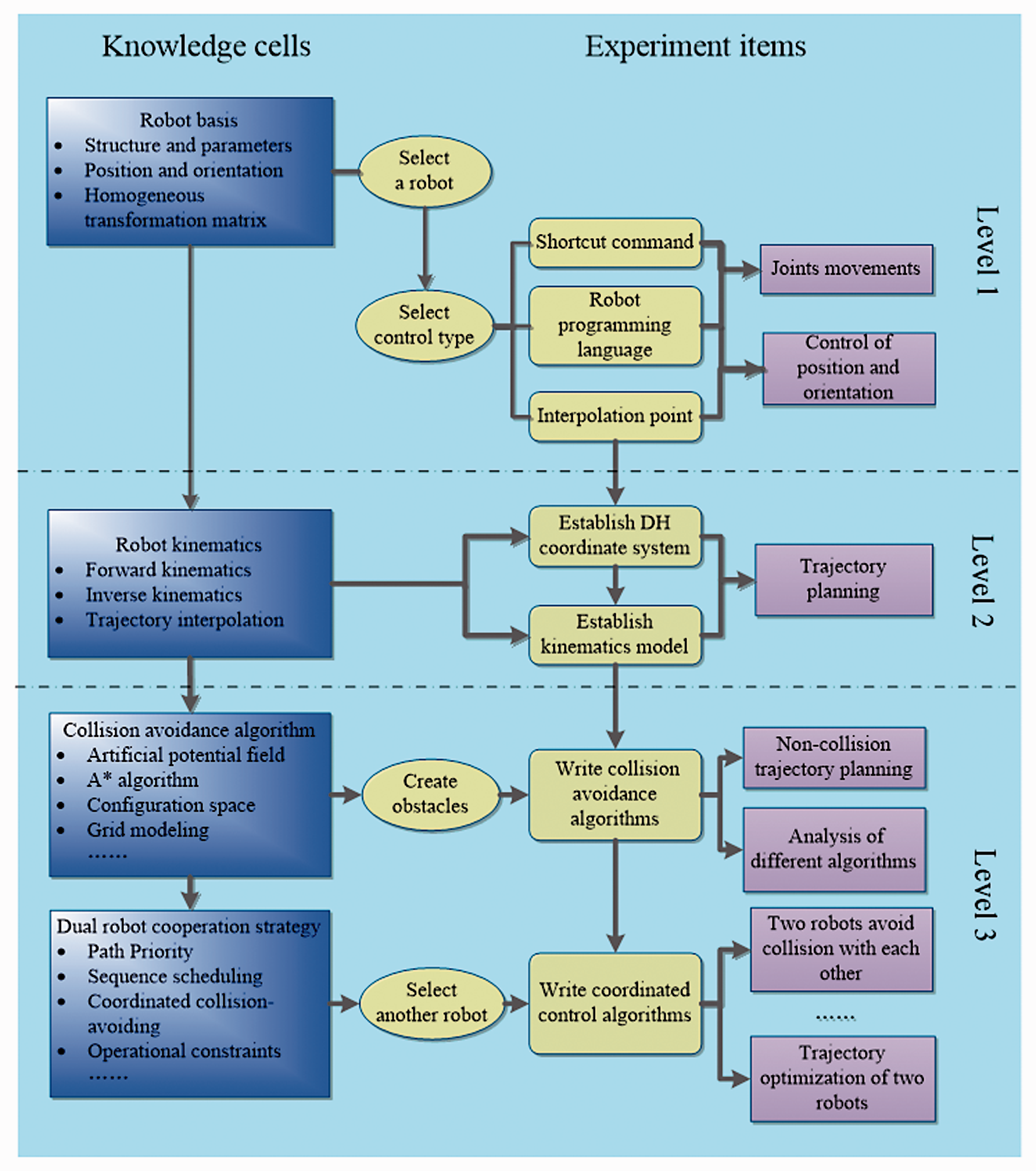
Execution experiments step-by-step.
Three specific examples are described briefly below.
VR application examples: facial trajectory planning and orientation control
The operation requires the end-effector of the robot to touch the face and move in a predetermined trajectory while ensuring that the mid-axis (Z-axis) of the end-effector is always collinear with the normal vector of the facial current contact point. A facial STL model can be imported into the simulation scenario. Through given triangulated surfaces data, students perform orientation planning and control. Figure 12 shows the simulation.
Robot facial trajectory planning and orientation control.
2. VR + on-site Application Example: Dual-robot collision-free trajectory planning
To verify the validity of the robot collision-free trajectory planning algorithm, a dual-robot coordinated trajectory planning experiment was designed. The robots ABB and SCARA each move from the starting point to the target point with overlapping work spaces, while there is a stationary obstacle and a moving obstacle in the environment. The moving obstacle moves linearly along the Z direction at a speed of 20 mm/s.
Figures 13 and 14 show part of the virtual simulation and the actual field experiment, respectively. In the figures, images (a) and (b) show that two robots move to their respective target points when no obstacle is encountered; images (c) and (d) show that the SCARA robot is avoiding the stationary obstacle, while the ABB robot is avoiding the moving obstacle; images (e) and (g) show that the two robots avoid each other; image (h) shows that both robots move to the respective target point.
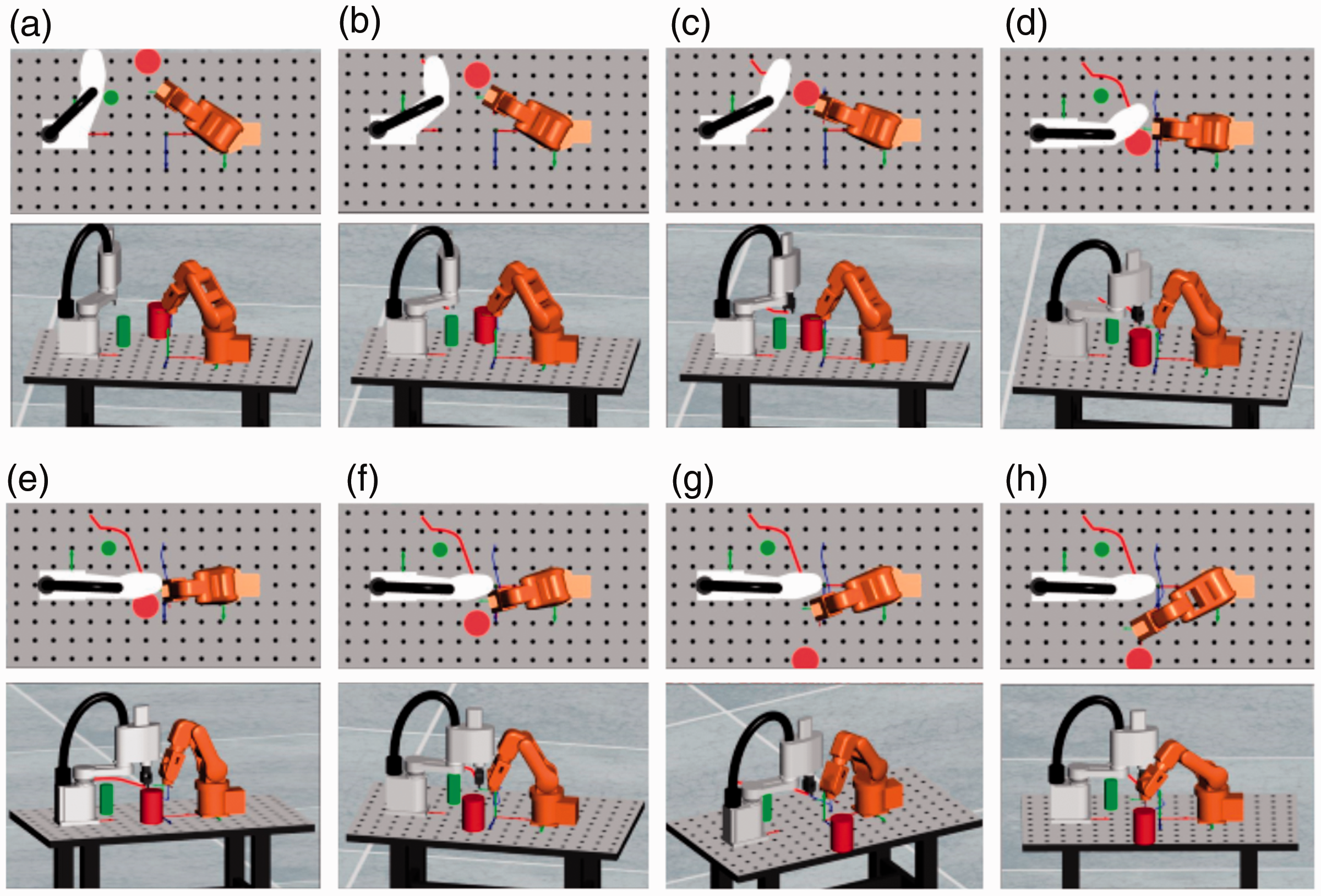
Virtual simulation experiment of double-robot’s avoiding collision.
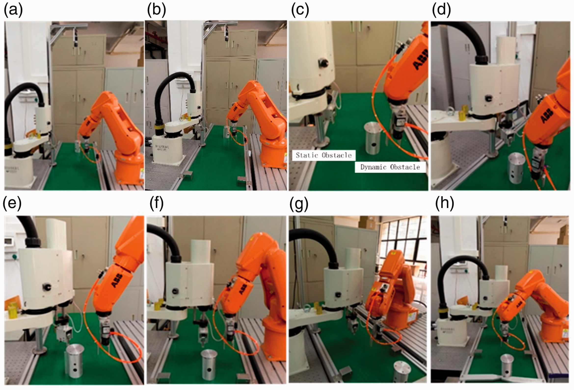
Actual experiment of double-robot’s collision avoidance.
3. VR + RC application example: robot trajectory optimization
Figure 15(a) shows a paper-cut pattern. Based on the profile data of the pattern, the trajectory of the robot is planned and optimized based on the shortest path. Figure 15(b) shows the robot working by RC and Figure 15(c) shows the results by virtual simulation and RC.
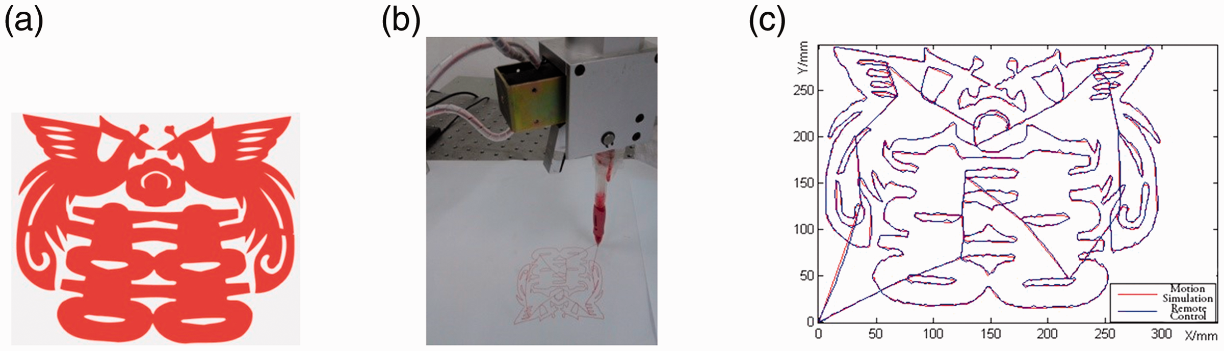
SCARA robot trajectory optimization. (a) Paper-cut pattern. (b) Remote-hand on the robot. (c). Trajectory comparison of VR and RC. VR: virtual reality; RC: remote control.
Evaluation
Questionnaires on new experimental mode are distributed and rated by 1 (lowest) to 5 (highest). Specific evaluation of statistical results from approximately 150 undergraduate students in the last three years are shown in Figure 16. For question 1 (Q1) that asked whether VR and RC experiments are flexible or convenient for their experimental schedules, sites or contents, 82.16% of the students gave a more than 4.0 evaluation. For question 2 (Q2) that asked whether Robot Kinematic Simulation is effective or helpful for their studies in the relevant knowledge of robots, no student gave a score of 3.5 or less, 57.14% gave a score between 4.0 and 4.5 points, while 23.81% gave a score between 4.5 and 5.0. In the question 3 (Q3) of HMI design, 80% of students gave more than 4.0 points.
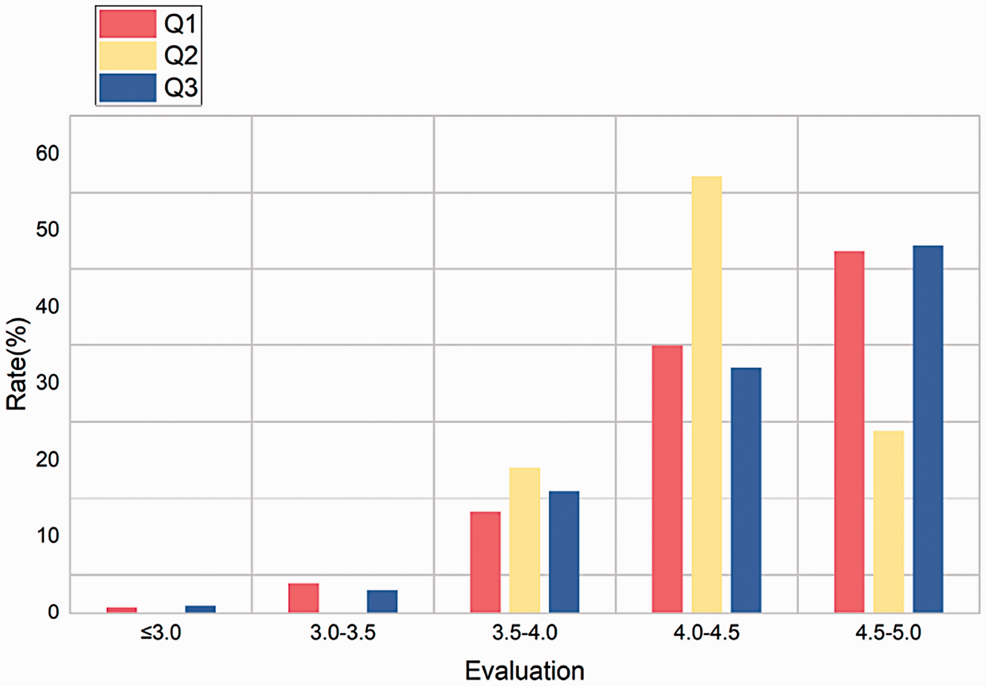
Questionnaire statistical results.
Conclusions
Robotics courses have been provided for undergraduate and graduate students majoring in mechanical engineering in universities or colleges, and an increasing number of robotics practitioners and enthusiasts wish to join the courses. The current laboratory robotic equipment and staffing cannot meet the rising need. In this study, a robot experiment teaching system integrating a variety of experimental modes has been established to meet the needs of learners studying at different levels. Robot VR simulation experiments and robot RC experiments are conducted as alternatives or complements to traditional on-site experiments.
Online virtual simulation experiment resources benefit a wide range of students and effectively solve such issues as expensive experimental equipment and potential security risks. RC experiments have solved the bottleneck problem associated with experiment teaching of distance education. Both experimental modes can effectively alleviate the shortage of laboratory personnel and laboratory space. The combination of multiple experimental modes usually performs simulation verification in a virtual environment and further manipulates the robot through RC or online experiment. Evaluations by students verify the flexibility and effectiveness of VR and RC experiments.
At present, the virtual simulation platform is limited to the motion simulation of two kinds of robots. In future, the simulation objects and contents can be further broadened. For example, a robot library can be built to provide more robots of varied types and sizes for analysis and comparison. In addition, the current platform cannot achieve collision detection between robots and between robots and obstacles, which needs to be addressed in future.
Footnotes
Acknowledgement
The authors sincerely thank Dr Ningning Zhou for her assistance in writing this article in English.
Declaration of conflicting interests
The author(s) declared no potential conflicts of interest with respect to the research, authorship, and/or publication of this article.
Funding
The author(s) disclosed receipt of the following financial support for the research, authorship, and/or publication of this article: This work was supported by funding from the Undergraduate Deep Reform Project of the Ministry of Education of China, Guangdong Province, Higher Education Teaching Reform Project and the SCUT Teaching Research Project.