
Abstract
Carnot’s general proposition, also referred to as one of Carnot’s principles, states that the work producing potential of heat—harvested by reversible heat engines—is independent of the working fluid and of engine internal details, being only a function of the temperatures of the reservoirs with which the engine exchanges heat. This concept, usually presented in introductory thermodynamics courses to ME students in the context of the second law of thermodynamics before entropy is introduced, is customarily proven by contradiction, i.e., by a violation of the second law, using second law concepts and abstractions such as ‘thermal reservoirs’ and ‘reversible engines’, without concrete examples, even though Carnot’s proposition mentions concrete things such as working fluids and engine internal details. This work proposes to document the usage of different reversible Stirling engine models that take the engine arrangement down to engine constructive parameters, crankshaft angles, and the like, as well as fluid properties into account towards illustrating the validity of Carnot’s general proposition without using entropy.
Keywords
Introduction
The subject of the second law of thermodynamics ranks among the most philosophical teaching topics in mechanical engineering. Many studies have been produced around the theme of pedagogical improvements in presenting the second law of thermodynamics, under a variety of strategies.1–6
One of the key concepts covered in textbook presentations of the second law is Carnot’s general proposition. Modern sources refer to Carnot’s general proposition in various ways, including ‘deductions that make up one principle’, 7 or ‘claim’ 8 (p. 88) —in the singular; or expand it and group it into ‘principles’, 9 or ‘corollaries’ 10 —in the plural.
Although Carnot’s original “Réflexions sur la puissance motrice du feu” 11 enunciates a fundamental principle (see below), what nowadays is referred to in multiple ways was actually named ‘general proposition’ by Carnot, and this text adheres to the original designation.
Carnot’s fundamental principle is a statement of a necessary condition for heat engines to attain “maximum” work production from heat
11
(pp. 56–57):
“[…] that in the bodies employed to realize the motive power of heat there should not occur any change of temperature which may not be due to a change of volume.”
Carnot’s general proposition, on the other hand, is the generalization of his fundamental proposition, and states that
11
(p. 68):
“The motive power of heat is independent of the agents employed to realize it; its quantity is fixed solely by the temperatures of the bodies between, which is effected, finally, the transfer of the caloric.”
Some mainstream texts9,10 present the topic in the context of the second law of thermodynamics, with two statements comparing the efficiencies (i) between irreversible and reversible heat engines, and (ii) among reversible heat engines, in every case operating between the same temperature reservoirs. Following the statements, the texts proceed with a formal proof by contradiction.
The proof technique of contradiction is commonly used in mathematics and consists in showing that the negation of the statement that one wishes to prove implies the impossible 13 —a method that is both sufficient and general from a mathematical viewpoint. In thermodynamics the impossible can be the violation of a law, thus in the case of Carnot’s general proposition, textbooks show that its negation implies the violation of the second law of thermodynamics.7,9,10
From a student standpoint, however, establishing the implication of violation of the second law from the negation of Carnot’s general proposition is an exercise done in a novel and heavily conceptual realm, in which abstractions such as ‘temperature reservoirs’ and ‘reversible heat engines’ are employed.
Despite the mathematical fitness of this approach, it lacks concrete examples. For instance, one may argue that lack of concrete examples may offer unnecessary extra difficulties on learners; moreover, the proposition’s phrasing seems to beg for concrete examples, as it mentions concrete things such as working fluids and engine internal details.
Keen and attentive learners may correctly wonder that both heat intake and net work output done by reversible models of different real engines may be written as complicated functions of the engines’ internal details, possibly including their internal configuration, part arrangements, constructive and operating parameters, crankshaft angles, part sizes and the like, working fluid properties, and reservoir temperatures—and wonder how all these things may fit together under the restrictions of Carnot’s general proposition.
This work focuses on documenting one such analysis, and thus becoming a reference that can be presented opportunely—not in place of, but alongside the usual proof by contradiction—to inquiring learners, or whenever an instructor sees to be fitting. Moreover, it is hoped that the concrete aspects of Carnot’s general proposition are met, at least in the few instances provided herein.
As far as the selection of cycles to base the intended illustration goes, one has to choose a reversible cycle so as to remain within the scope of Carnot’s fundamental principle and general proposition. Well-known engineering textbook reversible cycles include (i) the Carnot, (ii) the Stirling, and (iii) the Erickson ones. 9
Of these possibilities, the reversible Stirling cycle is of peculiar interest for the task due to (a) the current interest displayed towards it’s applications; 14 (b) the existence of many reversible models in the literature; 15 and mainly (c) the existence of three different Stirling engine configuration types: the α-, β-, and γ-ones—that will explicitly allow for variations of “engine internal details” mentioned in Carnot’s general proposition, and also of working fluid.
Additionally, the authors’ past research 14 and research supervision 15 activities associated with Stirling cycles and engines have played a definite role in favoring the choice of Stirling cycles over the Carnot and Erickson ones on illustrating Carnot’s general proposition, provided that any reversible cycle—and not only a Carnot one—can base the intended illustration.
Historically, reversible Stirling engine cycles have been proposed by Schmidt, 16 Finkelstein, 17 Walker 18 and Kirkley. 19 The focus of early works has been investigating optimal engine construction and operating parameters.
More recently, Cheng and Yang 20 developed a reversible, dimensionless, and parametric Stirling engine model that accounts not only for working fluid and for engine operating parameter variations, but also for engine configuration alteration, i.e., among the α-, the β-, and the γ-types. Moreover, they provide exact analytical expressions for net work output and for heat inlet that are written in terms of the various model parameters and engine internal configurations.
Following reasons (b) and (c) given above, the existing work of Cheng and Yang 20 is deemed ideally suited for the purpose of illustrating Carnot’s general proposition “in action” based on a concrete example—of reversible Stirling engines of various mechanical arrangements. Therefore, this work expands knowledge by the connections that are made and the insights that are registered in association to the aimed illustration, also in its production and documentation, rather than developing another Stirling engine model or one that is beyond Cheng and Yang’s work.
Reversible Stirling engine model
In this section, Cheng and Yang’s reversible Stirling engine model 20 is presented. Only a concise subset of the model that is useful for the goal of the present work is being presented.
Stirling engine configurations
In order to clearly depict the variations of engine internal details among Stirling engines of α-, β-, and γ-types, the following provides a basic description of the internal arrangements for these Stirling engine variants. Each configuration performs the same thermodynamic cycle, 21 but their mechanical arrangements; hence volume relations, differ, yielding peculiar model equations, as shown below.
The schematic for the α-Stirling engine type is depicted on Figure 1. The α configuration has two work-producing pistons, also known as ‘power’ pistons, that operate, under idealizations, at different fixed temperatures. The pistons oscillate out of phase by a mechanical arrangement, causing an alternating motion in the working fluid mass, indicated in the figure by the horizontal thicker arrows, thus making the working fluid to pass through the engine’s components.
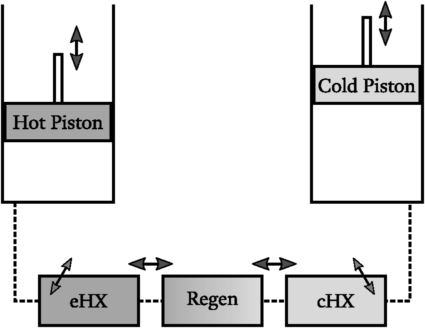
Schematic representation of an ideal Stirling engine of the α-type. Solid lines outline main components, while dashed lines represent working fluid connections between components. The ‘eHX’ and the ‘cHX’ are the ‘expansion’ and ‘compression’ heat exchangers, respectively kept by hypothesis at fixed high and low temperatures. The adiabatic ‘Hot’ and ‘Cold’ power pistons and the regenerator ‘Regen’ are indicated. Thicker vertical arrows indicate alternate piston motion, while thicker horizontal arrows indicate alternate working fluid motion. Inclined thinner arrows indicate heat exchange with the surroundings. Component shades of gray indicate temperature. Volumes are not to scale.
The simplest piston motion model assumes perfectly sinusoidal—a single frequency—movement of the pistons with respect to crankshaft angle, and is commonly found in the Stirling engine literature;16,17,20 other models can incorporate effects caused by constraints of the actual mechanical embodiment of a given engine, such as crank-rod equations.14,15
The schematic for the β-Stirling engine type is depicted on Figure 2. The β configuration has a single cylinder equipped with a ‘power’ piston and a ‘displacer’ piston. Similarly to the α configuration, these pistons also oscillate out of phase, with the mechanical restriction of non-collision between them.
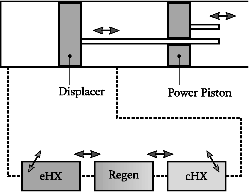
Schematic representation of an ideal Stirling engine of the β-type. Solid lines outline main components, while dashed lines represent working fluid connections between components. The ‘eHX’ and the ‘cHX’ are the ‘expansion’ and ‘compression’ heat exchangers, respectively kept by hypothesis at fixed high and low temperatures. The adiabatic ‘Power Piston’ and ‘Displacer’ and the regenerator ‘Regen’ are indicated. Thicker arrows next to piston rods indicate alternate piston motion, while thicker horizontal arrows about the regenerator indicate alternate working fluid motion. Inclined thinner arrows indicate heat exchange with the surroundings. Heat exchanger and regenerator shades of gray indicate temperature. Volumes are not to scale.
While in the α configuration the pistons are responsible for working fluid motion and work production, in the β configuration each piston has a more clearly defined task. For instance, the displacer piston is mainly responsible for working fluid displacement inside the engine, to and from the high- and low-temperature sides; while the power piston is mostly responsible for work production and overall working fluid pressurization.
The schematic for the γ-Stirling engine type is depicted on Figure 3. In one hand, similarly to the β-type Stirling engine, the γ Stirling engine configuration has separate ‘power’ and ‘displacer’ pistons and the aforementioned clearer separation of tasks; on the other hand, the γ configuration provides separate cylinders for each piston.
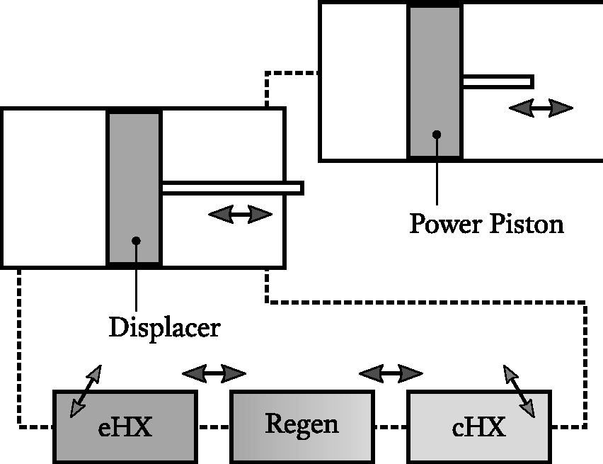
Schematic representation of an ideal Stirling engine of the γ-type. Solid lines outline main components, while dashed lines represent working fluid connections between components. The ‘eHX’ and the ‘cHX’ are the ‘expansion’ and ‘compression’ heat exchangers, respectively kept by hypothesis at fixed high and low temperatures. The adiabatic ‘Power’ and ‘Displacer’ pistons and the regenerator ‘Regen’ are indicated. Thicker arrows next to piston rods indicate alternate piston motion, while thicker horizontal arrows about the regenerator indicate alternate working fluid motion. Inclined thinner arrows indicate heat exchange with the surroundings. Heat exchanger and regenerator shades of gray indicate temperature. Volumes are not to scale.
Model presentation
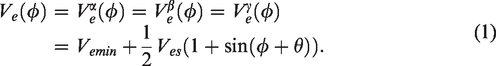
Cheng and Yang’s model 20 nomenclature is kept mostly the same as the one used in the original reference, 20 so as to allow readers to easily lookup in the original work the parts herein abridged. There are only minute changes in the employed nomenclature for conciseness, which consist in (i) annotating the Greek letter of the engine configuration above a symbol, so as to specify that symbol’s expression for that particular engine configuration, starting on equation (1), which requires (ii) renaming the expansion-to-compression phase angle from the original ‘α’ to the current ‘θ’.
Let Vcs and Ves be piston and displacer sweep volumes in the operation of a reversible Stirling engine of either α-, β-, or γ-type—in Stirling engine nomenclature, it is common to name high and low temperature spaces and adjacent moving parts as ‘expansion’, and ‘compression’ ones, respectively, see Figures 1 to 3 that illustrate the ‘expansion’, and ‘compression’ heat exchangers; hence the ‘c’ and ‘e’ subscripts.
Let further Vr be the regenerator volume, Vd be the so-called engine “dead volume”, which is composed by piston and displacer minimum clearances and regenerator volumes, i.e.,
Let
The compression volume,


It is worth noting that each engine has its very own distinct volume dynamics, making them suitable to verifying Carnot’s general proposition from the point of view of “different internal details”.
Let the total engine volume—the instantaneous volume occupied by the engine’s working fluid


The working fluid pressure, p, is assumed to be uniform throughout the engine cavity—as internal pressure-drops
b
(throttling effects) introduce irreversibilities
8
(pp. 369–370) that would prevent one from verifying Carnot’s general proposition in such models. Assuming, for the sake of simplicity, while still allowing for different fluids to be used, ideal gas p-V-T behavior of the working fluid, one has
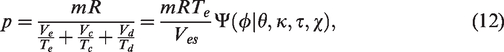

The dimensionless pressure function is a multi-term, engine configuration dependent expression


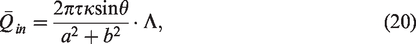
The RTe-normalized (i) specific net cycle work,
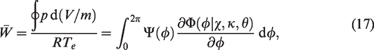
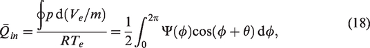
Equations (17) and (18) embody the argument made on the Introduction section of this work, meaning that both cycle net work and cycle inlet heat expressions are complicated and different functions of the engine’s internal details—whether in terms of α-, β-, or of γ-type configurations, but also of construction/tuning parameters such as θ, κ, and χ—and of the thermal reservoir temperatures, τ.
Illustration of Carnot’s general proposition
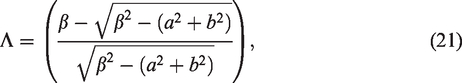
Solutions to the integrals of equations (17) and (18) are given by Cheng and Yang,
20
which applied the residual theorem. The resulting expressions are
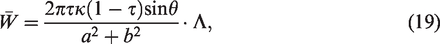


Although the cycle net work, Are indeed the same: Are equal to any reversible engine’s thermal efficiency, Are indeed a function of only the reservoirs’ temperatures:
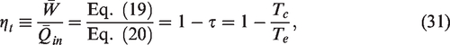
Therefore, the reversible α-, β-, and γ-types Stirling engine models of Cheng and Yang, 20 are shown to follow Carnot’s general proposition, according to the second law of thermodynamics.
The worked out illustration serves thus as an instance of defined reversible engines with different internal details and working fluids of possibly different properties, whose thermal efficiencies are restricted by Carnot’s general proposition, despite the fact that their net work and inlet heat are different and complicated functions of the various working parameters and engine configuration.
Following reference,
20
the present illustration employs the ideal gas fluid model, which allows for fluid property variations, through the fluid’s molecular weight M, since
In one hand this choice avoids further and unnecessary c complications in the work and heat integral solutions, equations (19) and (20), but it does limit the analysis to working fluids behaving as an ideal gas. This is a natural outcome of the present initiative to provide an example, a concrete instance of illustration of Carnot’s general proposition, not replacing the proof by contradiction, which meets the generality requirements for a physical principle enunciated in mathematical terms.
Conclusions
This work has illustrated the validity of Carnot’s general proposition 11 by using a parametric, reversible Stirling engine model from the literature 20 that takes into account engine geometry and working fluid properties. Moreover, the analytic nature of the model, with its exact solution, helps in keeping the illustration concise and exact, and generic up to the model’s modeling space.
In one hand, the example illustrated herein is less generic and less conceptual (i.e., more instantiated) than the canonical proof by contradiction using only general concepts, usually presented in thermodynamics courses and textbooks,7,9,10 and therefore, evidently does not serve as a general replacement of the proof by contradiction.
On the other hand, the illustration based on a reversible model of a real engine is more defined and hopefully more palpable and interesting to inquiring students. One can argue that at least the illustration complements the proof by contradiction and may boost interest by the more concrete approach.
Footnotes
Acknowledgements
All authors acknowledge the Federal University of Technology – Paraná (UTFPR) and the Federal Institute of Education, Science and Technology of Santa Catarina (IFSC), who contributed to this study in providing human resources, laboratories, and institutional access to bibliography databases. To YHWH God be the glory!
Authors contribution
CN: Conceptualization, Methodology, Writing - Original Draft, Writing - Review & Editing, Writing -- Review & Editing (figures), Project administration. KAEB: Methodology, Investigation, Writing -- Original Draft (figures), Writing -- Review & Editing. JMSL: Methodology, Resources, Writing -- Review & Editing, Supervision, Funding acquisition.
Declaration of conflicting interests
The author(s) declared no potential conflicts of interest with respect to the research, authorship, and/or publication of this article.
Funding
The author(s) disclosed receipt of the following financial support for the research, authorship, and/or publication of this article: KAEB and JMSL acknowledge the financial support in part by the Coordination of Improvement of Higher Education Personnel -- Brazil (CAPES) -- Finance Code 001, the National Council for Scientific and Technological Development (CNPq), the Foundation Araucária (FA) and the Financier of Studies and Projects (FINEP).