
Abstract
Herein, we present a dynamic analysis on a Whitworth quick return mechanism, which was proposed as a class project to engage Mechanical Engineering students in the Machine Dynamics course. The objectives of the project are to teach (1) kinematic analysis on planar linkage mechanism using complex numbers and (2) kinetic analyses using distributed and lumped mass models. The analytical models were implemented using an engineering math software – Mathcad, and the results were validated by a multibody dynamics simulation software – Inventor. Loop closure equations were first built and solved to find link positions, and then velocities and accelerations were confirmed with numerical differentiation in Mathcad. Based on the solved kinematic quantities, a kinetic analysis was carried out using distributed and lumped mass models as well as in Inventor. The reactions and torques at the input link of the distributed mass model were found identical to those derived from Inventor. It was found the maximum reactions at pin joints were 11% to 100% different between the distributed mass model and the simplified lumped mass model. However, the shaking forces found in both models were nearly identical, and the peak values of the shaking moments were comparable. It is confirmed the lumped mass model can serve as a quick method to find the magnitude of the shaking forces and moments without solving simultaneous equation systems.
Introduction
Whitworth quick return mechanisms are widely used in numerous industrial applications such as shapers, power-driven saws, and mechanical actuators. In those applications, a load-intensive working stroke is required with a low-load return stroke. The time spent in the working stroke divided by the return stroke defines a time ratio greater than unity. Several basic 4-link mechanisms feature quick-return actions, including crank-slider mechanisms and four-bar mechanisms. Rao1 designed a four-bar crank lever mechanism to achieve a given time ratio and angle of oscillation. Hsieh and Tsai 2 tested the feasibility of combining a generalized Oldham coupling with a slider-crank mechanism.
Whitworth quick return mechanism has six links consisting of a driving crank with a constant angular velocity and a ram with reciprocating actions featuring a quick return stroke. Research has been focused on designing the mechanism for various applications. Dwivedi 3 modified the mechanism for use in high-velocity impact presses. Lin et al. 4 introduced it as the actuating unit of pots for automatic cooking - the time ratio of cooking and pot retrieving is greater than 1.4 using their design. Ying and Cheng 5 employed the mechanism to develop a bag-breaking device, whereas Endeshaw et al. 6 explored the feasibility to mount a piezoelectric energy harvester on the Whitworth quick return mechanism. Recently, Shyam et al. 7 used Whitworth quick return mechanisms to improve the efficiency of stationary concrete pumps. Although traditional analytical and graphical methods are widely used in mechanism design, nowadays, computer-aid programmes have streamlined the design process. Echempati 8 implemented the Whitworth quick return mechanism project in Microsoft Excel, and the mechanism was modelled in a Catia CAE software. Zhou and Chen 9 modelled and simulated a sharper quick-return mechanism in Automated Dynamic Analysis of Mechanical System (ADAMS). Cheetancheri and Cheng 10 developed an Excel-based mechanism analysis toolkit.
In this study, we utilized the analytical method along with the computer programmes (Mathcad 15, Inventor 2021) to solve the kinematic and kinetic quantities of the Whitworth quick return mechanism. The technical goal is to formulate kinematic and kinetic relationships as well as to model the mechanism in modern software. The analytical results were first derived and then validated against the numerical values. In addition, the difference between distributed mass model and lumped mass model was explored. We attempted to provide insight into the strength and limitations of the lumped mass model - a question that was not answered in a standard textbook. 11 The complete solution to the mechanism, including the Mathcad scripts and CAD files, are provided for researchers to modify and tailor for specific needs. The models can be adopted in the courses covering planar linkage mechanisms. At Penn State Behrend, the projects described in this work were assigned to mechanical engineering students in the ME-380 Machine Dynamics and completed within the first eight weeks. Our previous study 12 showed that introducing practical applications to students is beneficial to their comprehension and engagement. After completing these projects, students should be able to: (1) analyze the kinematics of planar linkage mechanisms, (2) use Mathcad to solve complex machine dynamics problems or systems, and (3) model/simulate planar linkage mechanisms in Inventor.
Methods
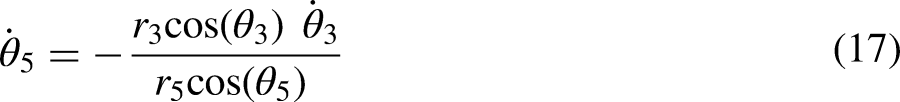
The Whitworth quick return mechanism is shown in Figure 1. Six links were numbered, and seven kinematic pairs were identified, including five turning pairs between links 1–2, 1–3, 2–4, 3–5, and 5–6, and two sliding pairs between links 3–4 and 1–6. The mobility was determined using Gruebler's equation
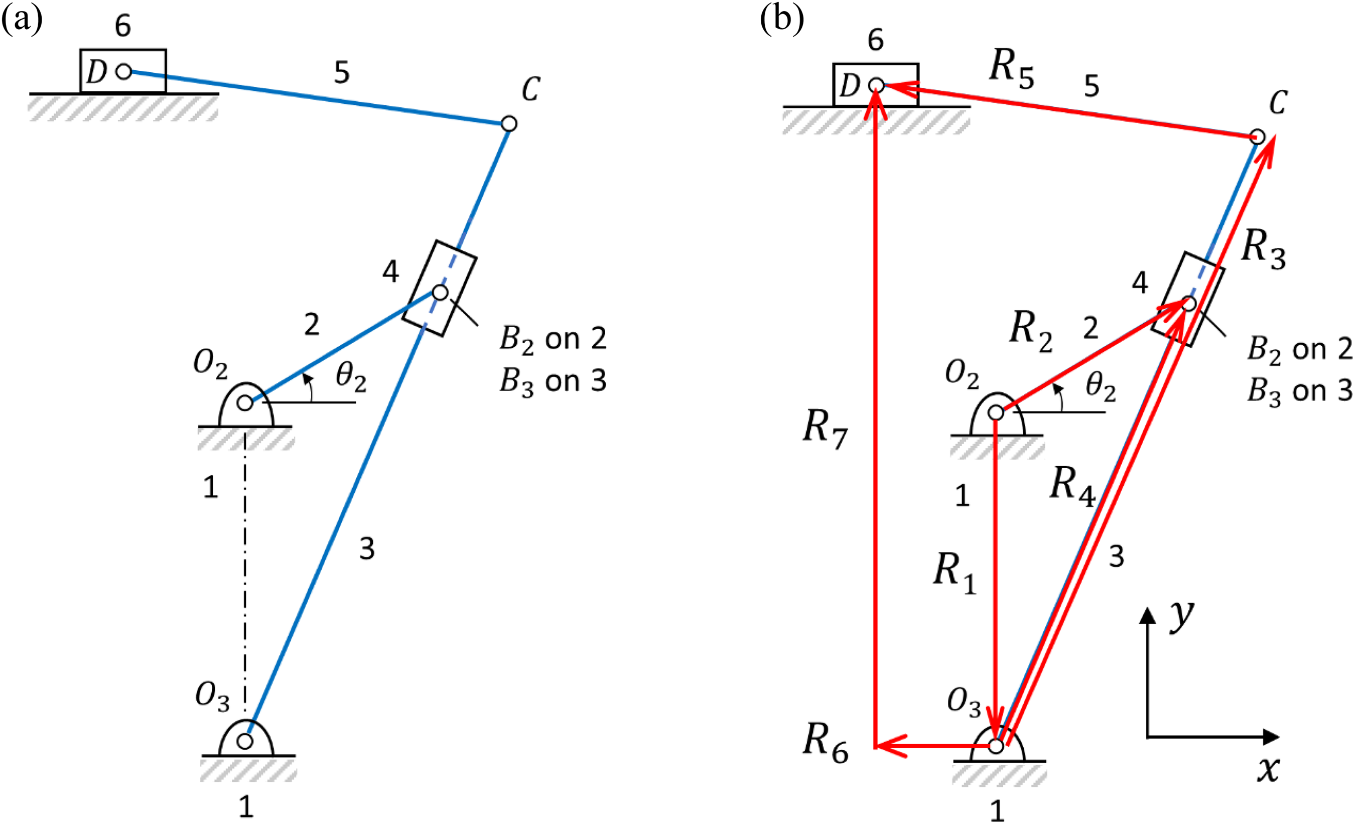
(a) skeleton diagram and (b) vector loops for the Whitworth quick return mechanism. The x and y are the real and imaginary parts, respectively.
Kinematic analysis
Two loops were built, as shown in Figure 1, to traverse the Whitworth quick return mechanism along the links and through kinematic pairs. The primary loop covers the driving crank, the base links, and the slotted slider (


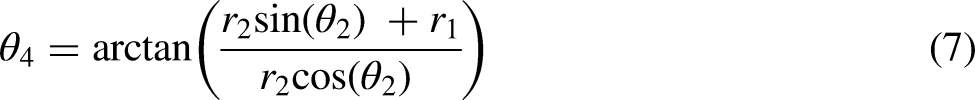
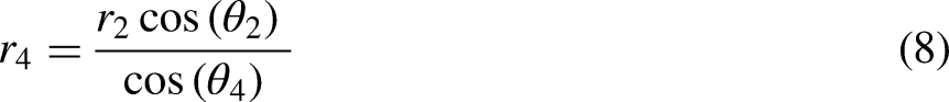
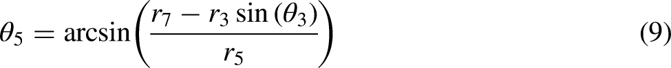


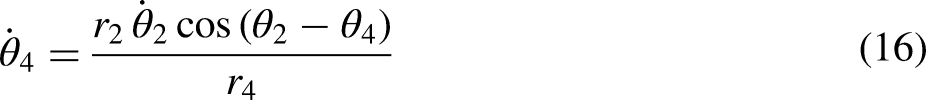


To solve


Static analysis
The driving torque from the crank is transmitted to the working slider through multiple kinematic pairs and links. In this static force analysis, it is assumed that the kinematic pairs were frictionless, and the links were rigid bodies. When a constant external force is applied on the slider (link 6), a torque

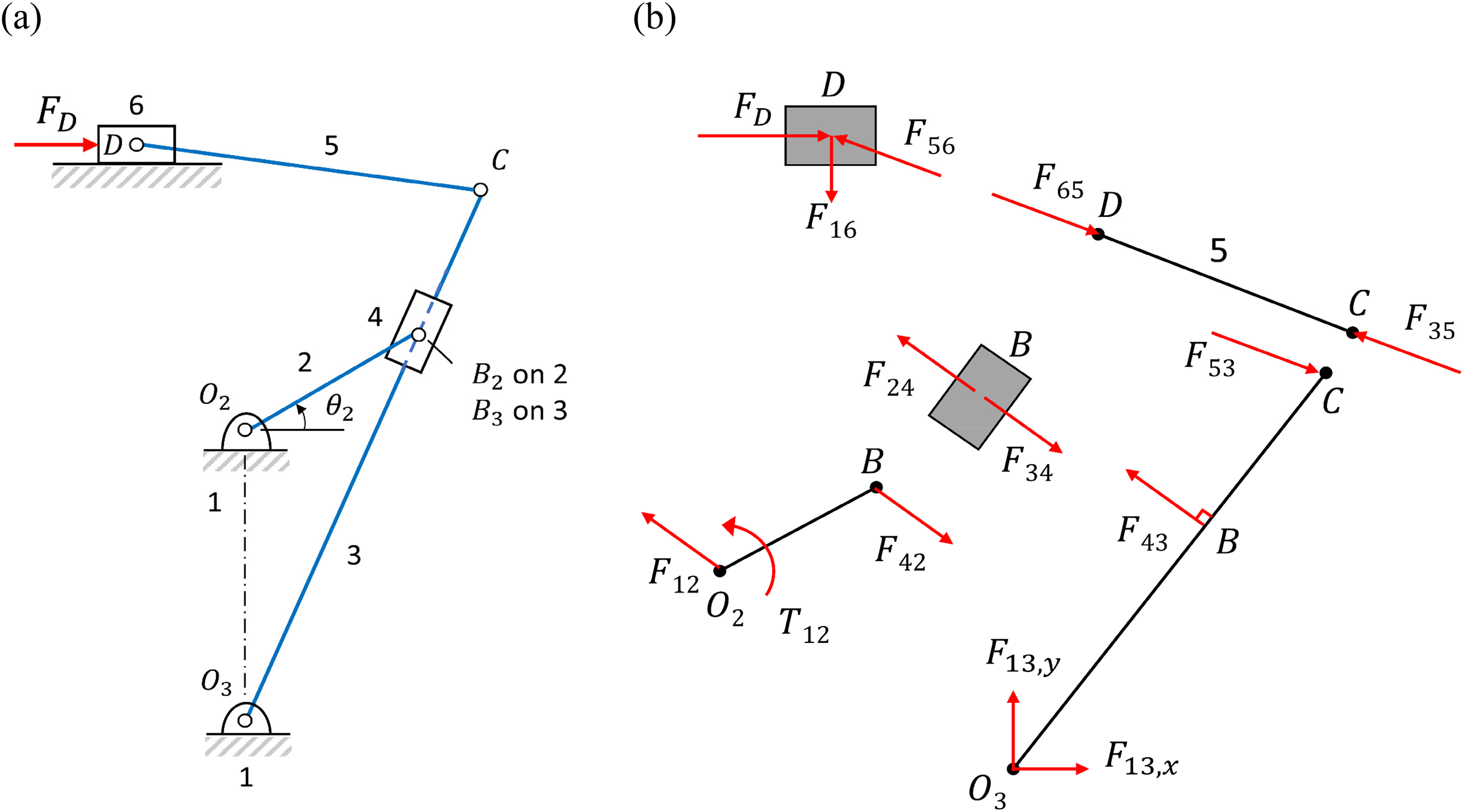
(a) mechanism subject to an external force and (b) free-body diagrams of individual links.
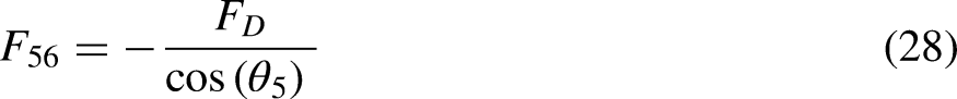
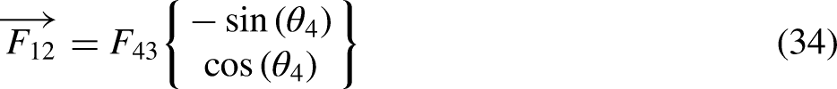
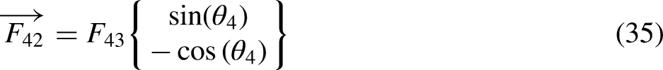
Two unknown forces


Dynamic analysis – distributed mass model
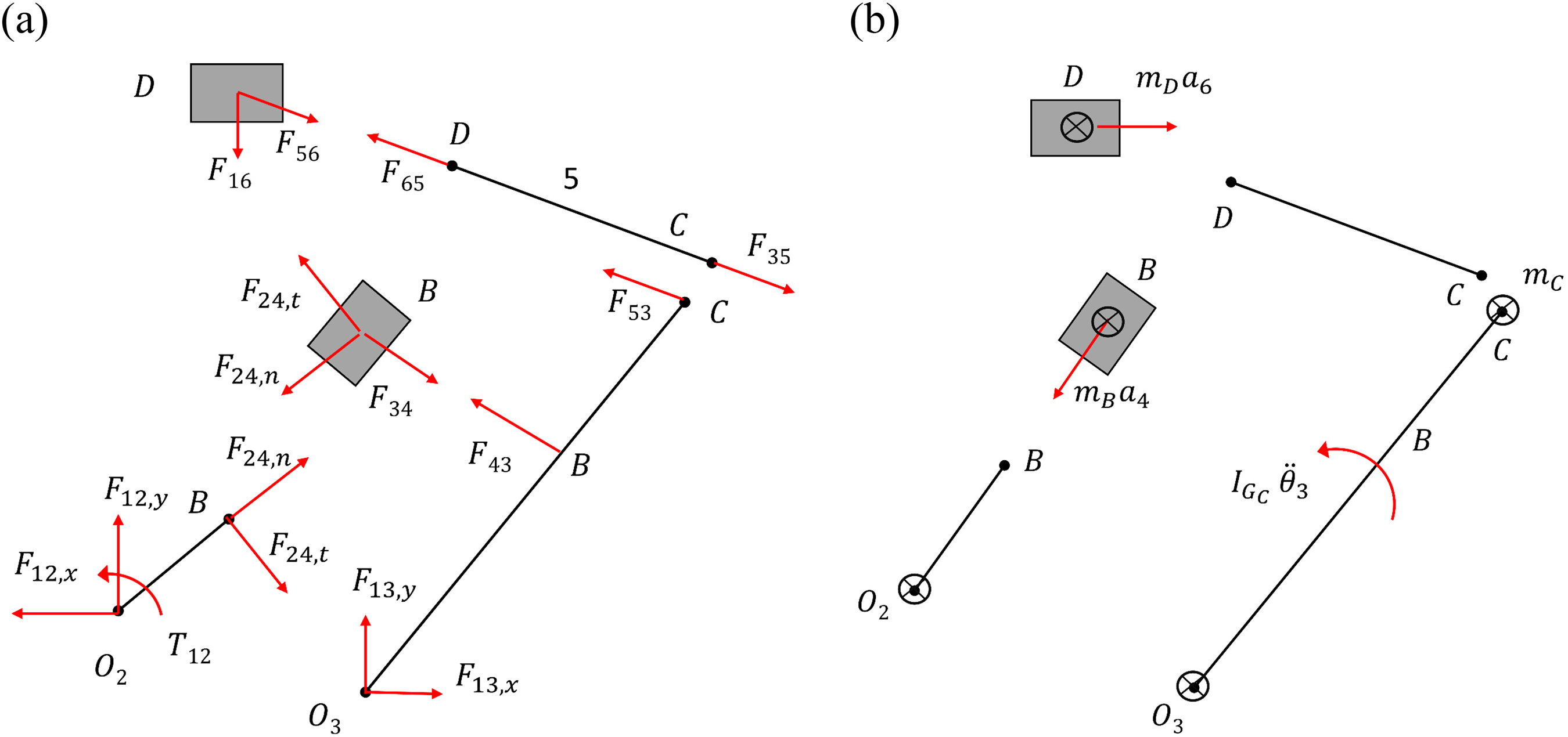
Kinetic analyses of the Whitworth quick return mechanism are based on the governing equations of motion, requiring solved kinematic expressions. As shown in Figure 3, there are 13 unknowns from the FBD, namely,
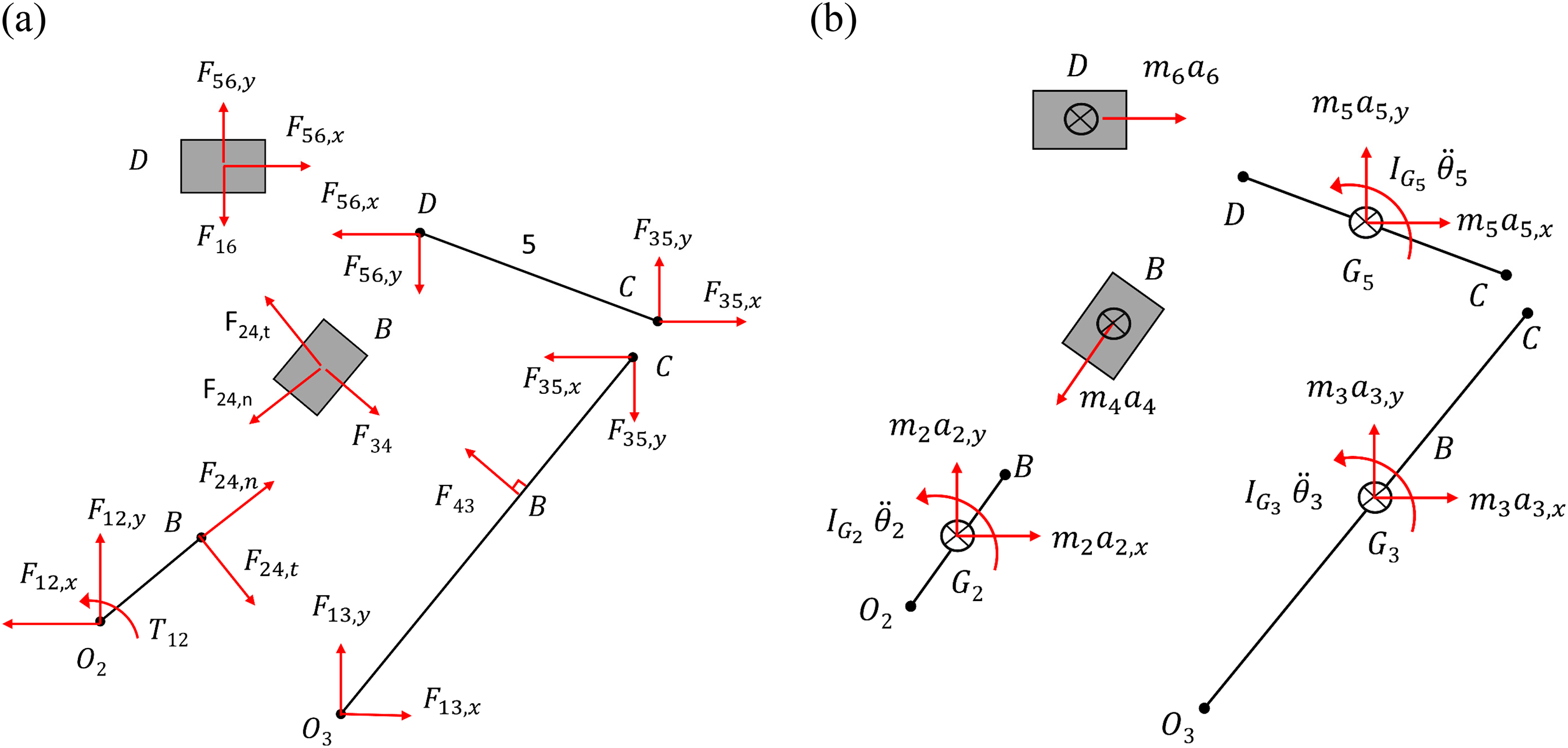
(a) free-body diagrams and (b) kinetic diagrams of the distributed mass model.
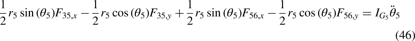
In order to solve these unknowns, 13 equations must be derived from the kinetic diagrams (KD) to form a simultaneous linear equation system. The unbalanced inertia of the moving links causes the shaking forces defined as:


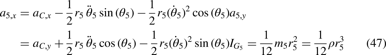


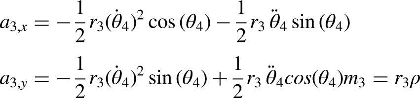
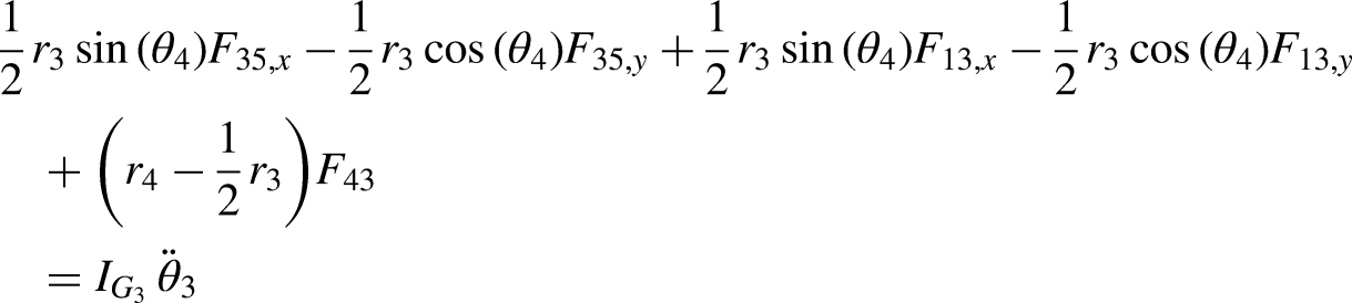
link 2:


A simplified way to find the shaking forces is to use a lumped mass model, which requires the mass of links to be allocated only at the joints. Link 5 becomes a weightless two-force member, as shown in Figure 4. This treatment guarantees the same total mass and the centre of mass; however, it changes the polar mass moment of inertia. Therefore, it is expected the reactions at links differ from the distributed mass model. Assume the all the links were uniform and masses were accolated at two end joints, giving

(a) free-body diagrams, and (b) kinetic diagrams of the lumped mass model.
Apply Equation of Motion to solve for link 6,


link 4


link 2


The unknowns listed above can be solved in sequential order, similar to the static analysis. The shaking forces are the summation of all forces acting on the base link 1:


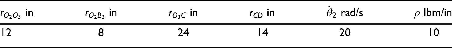
Scaled parameters used in simulating the Whitworth quick return mechanism.
Results and discussion
Model validation
The positions, velocities, and accelerations of slider 6 are presented in Figure 5a-c. It can be seen that the analytical values (

Positions (a), velocities (b), and accelerations (c) of the slider 6; reactions in x-direction (d), y-direction (e) and input toque on (f) the crank link 2. The subscript ‘int’ denotes the results from Inventor, whereas ‘sol’ corresponds to the distributed mass model.
Magnitude (a) and direction (b) of the vector
Figure 5(d)-f compares distributed mass model with Inventor results through the reactions in the x-direction (d), y-direction (e), and input toque on the crank link 2. It can be seen from Figure 5(d), the reaction of link 2 in the x-direction has the same trend as the slider acceleration in Figure 5(c), indicating the reaction (
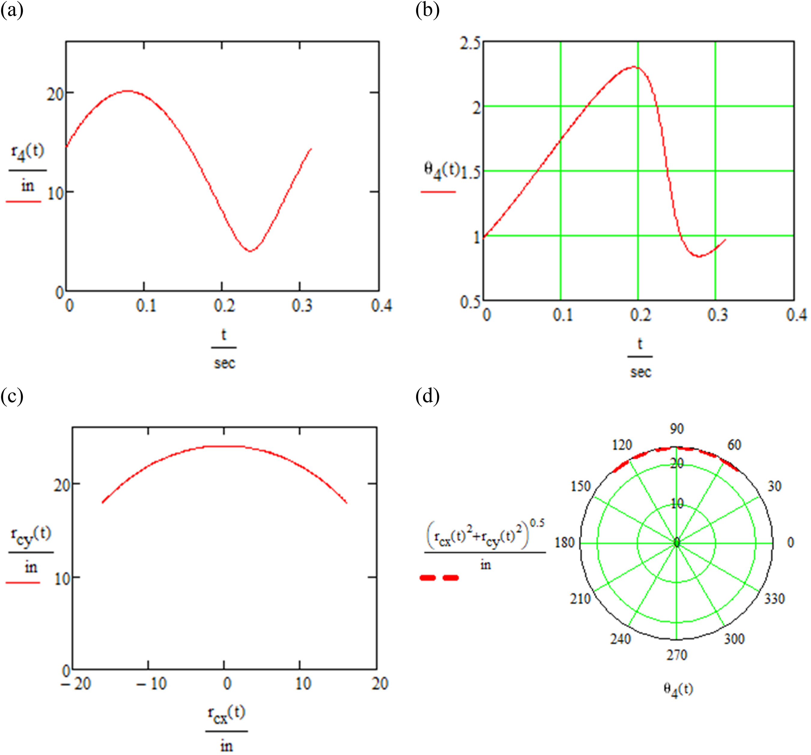
Kinematics
Some of the link positions were plotted in Figure 6. It can be seen from Figure 6(a), the maximum length of link 4 is 20 in, which occurs when slider 4 is right above the pivot
Statics
When an external load of 5 lbf is applied on slider 6, the x-component of
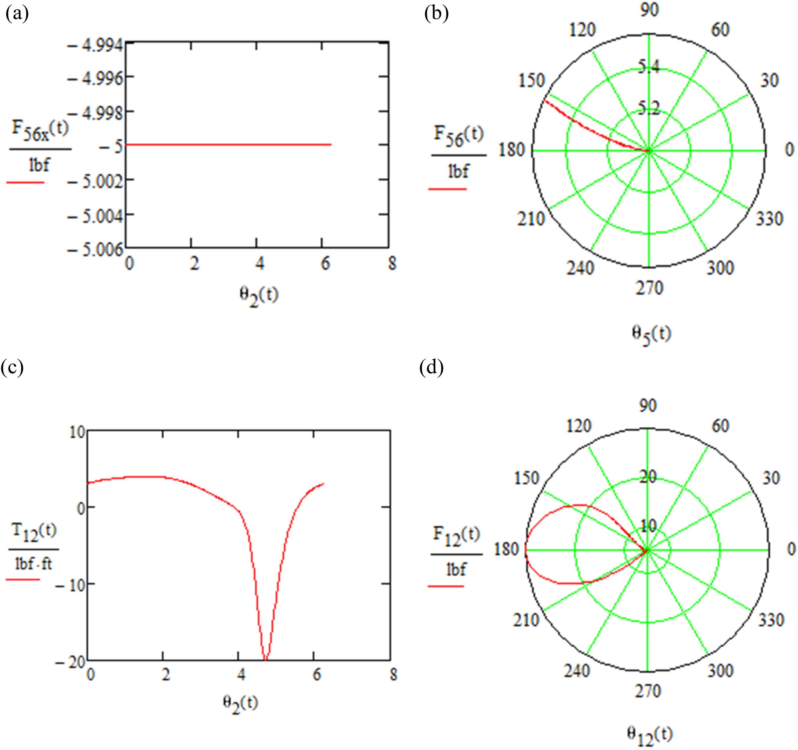
Reaction at joint D in the x-direction (a) and in a polar coordinate (b); the torque needed to balance the mechanism (c) and the reaction in at
Kinetics – lumped versus distributed mass model
Pin forces and the shaking force were derived from the distributed and lumped mass models. It can be seen from Figure 8(a), the pin force from the lumped mass model tends to underestimate the reaction at point C except for the low angles around 0 degrees. Although both models predict maximum pin forces on the same magnitude of order, the maximum reaction derived from the lumped mass model P35 is about
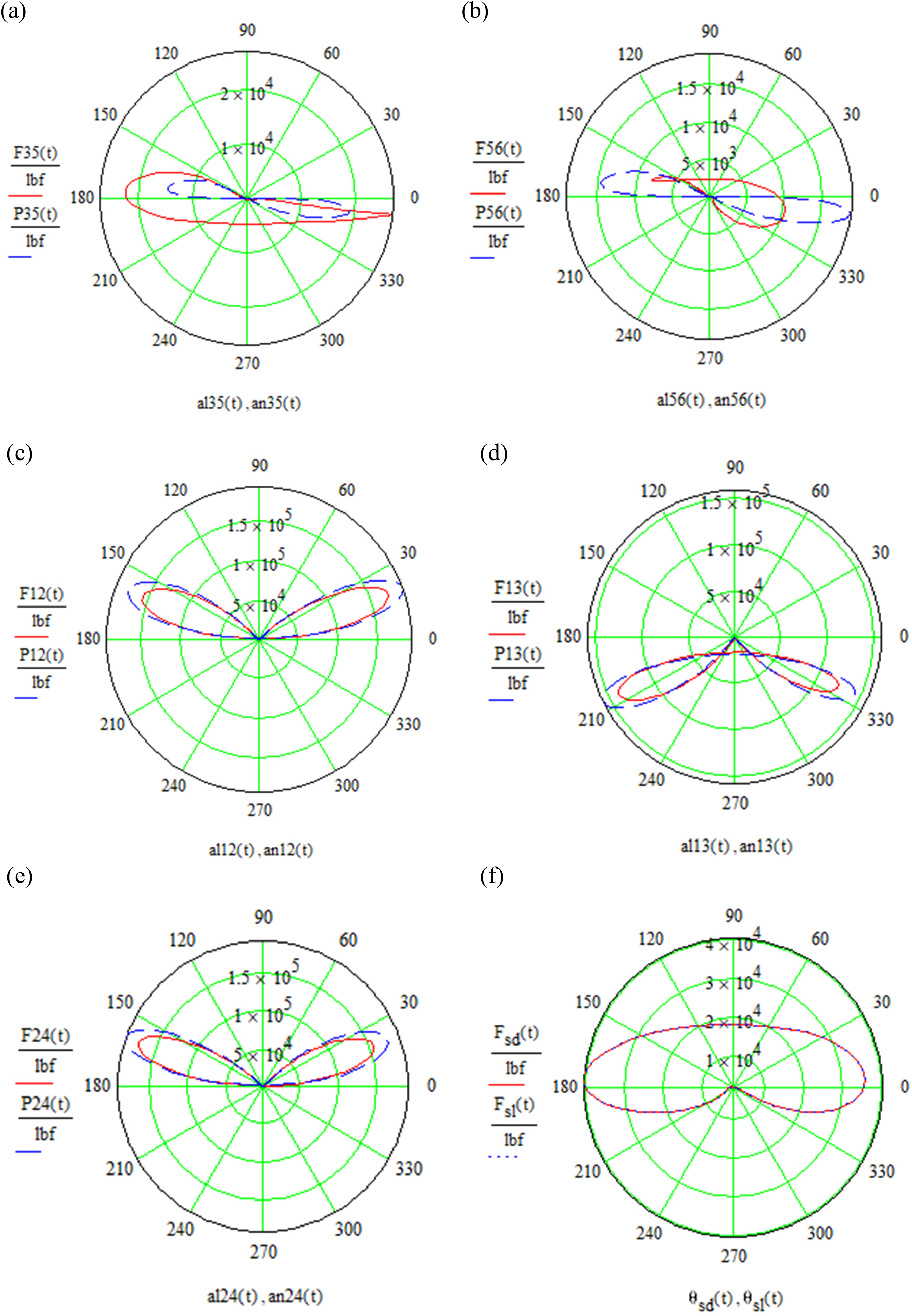
Reactions at joints C (a), D (b),
Despite the identical shaking forces, Figure 9a shows the shaking moment in the lumped mass model is slightly higher than the distributed model. The deviation is expected as the lumped model relaxed the constraint on the polar mass moment of inertia. Intuitively, half mass at a double distance will increase the polar mass moment of inertia as
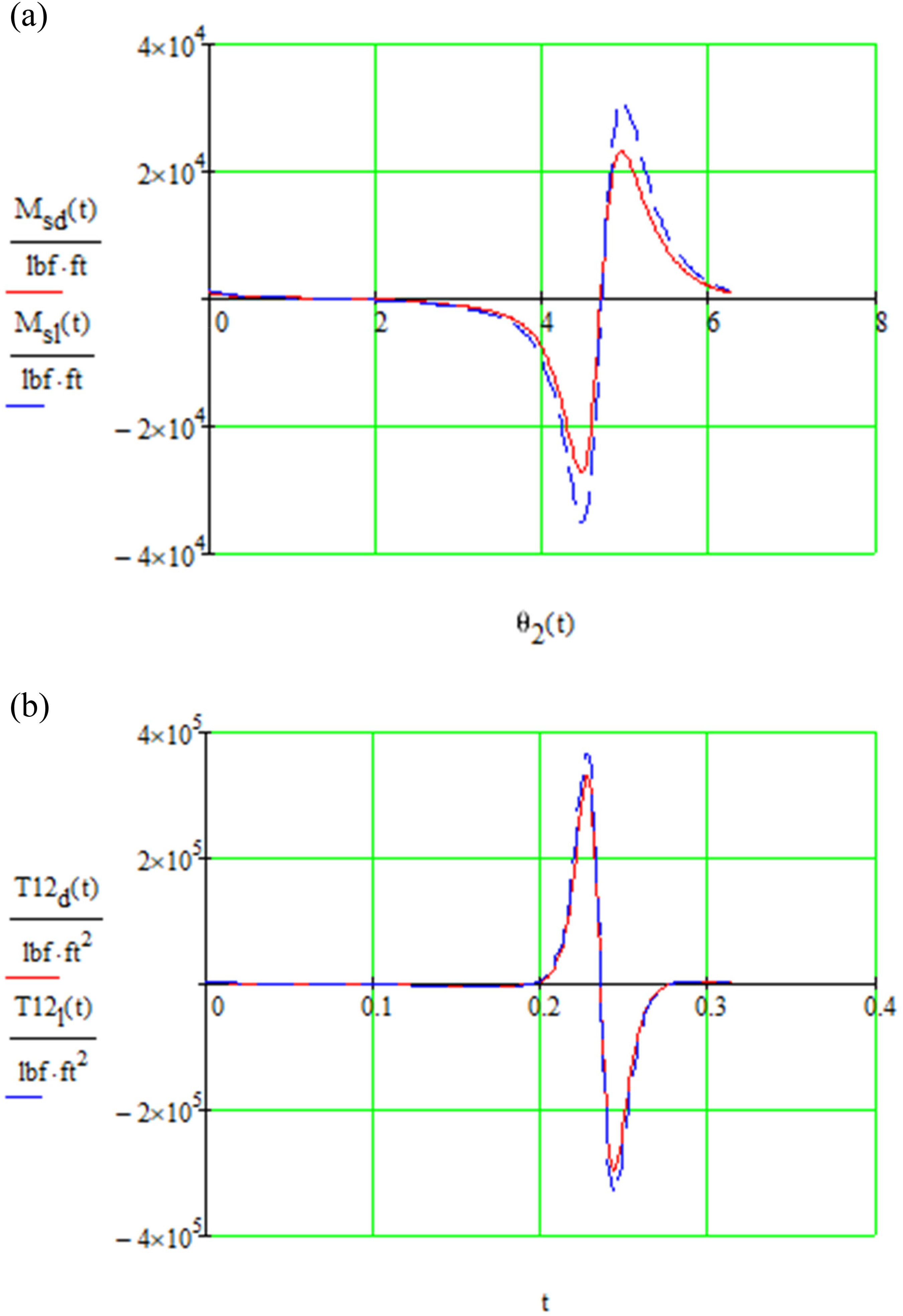
Shaking moments (a) and torques (b) at pivot
Conclusion and future works
A Whitworth quick return mechanism was modelled using a complex number method to analyze the kinematics. The analytical expressions derived from loop closure equations were exactly identical to the numerical results. Based on kinematic quantities, static and dynamic analyses were performed. The distributed mass model was directly validated by Inventor, whereas the lumped mass model was indirectly validated by reducing it to a static model. The static analysis assumed links 4 and 5 as two force members found a maximum torque of 20 lbf·ft is needed to withstand the 5 lbf external load. Pin reactions, shaking moments, and forces were compared in lumped and distributed mass models. The maximum deviations of the pin reactions occur at joint D, where the lumped model overestimates the maximum reaction at
At Penn State, Mathcad and Inventor modelling are taught in a first-year engineering design class (EDSGN 100: Cornerstone Engineering Design), and they are proven with the ease of usability for engineering students to analyze any linkage mechanisms. Our future works will take aim at evaluating the course outcomes, i.e., after completing these projects, students should be able to: (1) analyze the kinematics of planar linkage mechanisms, (2) use Mathcad to solve complex machine dynamics problems or systems, and (3) model/simulate planar linkage mechanisms in Inventor. We also plan to assess student perceptions of the project-based learning (PBL), specifically on team-based PBL, to determine whether the proposed projects would promote active learning and help students develop engineering soft skills.
Footnotes
Acknowledgements
This work is supported by Miami University New Faculty Research Fund.
Declaration of conflicting interests
The author(s) declared no potential conflicts of interest with respect to the research, authorship, and/or publication of this article.
Funding
The author(s) received no financial support for the research, authorship, and/or publication of this article.