
Abstract
In senior-level robotics courses, students often struggle to connect analytical models of differential drive kinematics and control with the behavior of real mobile robots, particularly when non-holonomic constraints and ROS2 based software architectures are involved. This article presents an experiential learning framework for teaching non-holonomic mobile robot kinematics, odometry, and closed-loop control using a ROS2 enabled Ati Sherpa RP differential drive platform. The four-week module combines platform-specific derivation of inverse and forward Jacobians with simulation-based validation in IR Sim and subsequent deployment to physical hardware. The framework was implemented with final-year mechanical engineering students, and its educational effectiveness was evaluated using pre-/post-quizzes, rubric-based assessment of simulation and hardware exercises, and a post-module survey. Results show marked conceptual gains (pre-quiz mean 46% vs. post-quiz mean 81%, Cohen’s
Keywords
Introduction
Mobile robotic platforms have become integral components in modern engineering programs where they are used to support instruction in kinematics, feedback control, and autonomous navigation.1,2 Among the range of mobile robot architectures that are commonly deployed in educational laboratories, the differential drive configuration is most commonly adopted, especially because the mechanical simplicity of this configuration matches the trends of industrial services. Nonetheless, students have a tendency to fail to translate theoretical descriptions of the differential drive mechanics into practical control systems that can work satisfactorily on a real or simulated robotic system. 3 These systems also introduce a key implementation challenge associated with non-holonomic motion constraints. Given that the lateral translation is impossible in these robots, students need to learn to coordinate the linear and angular velocities to move in the desired direction precisely. Although most of these limitations are well documented in the standard robotics literature, students often find it challenging to apply forward and inverse kinematics, odometry, and closed-loop control algorithms in practice. This gap can be exacerbated when students must integrate their models into a full-featured robotics middleware such as ROS2, where seemingly minor modeling inaccuracies in the kinematic layer can propagate and degrade high-level navigation behavior. Some educational robotics frameworks emphasize abstract kinematic models and simulation with limited exposure to deployment-level software.2–4 In contrast, other approaches prioritize project work and software tools, sometimes without making the underlying Jacobian structure explicitly.3–5 Consequently, students can obtain functional demonstrations without knowing the detailed kinematic and control principles that guide robot movement. This paper presents an education-oriented framework for teaching non-holonomic mobile robot kinematics and control using a complete and platform-calibrated development workflow. The proposed methodology guides the learners from geometric modeling and Jacobian derivation to odometry calculation, and proportional–integral (PI) control in order to manage the robot in tracking a trajectory and navigate autonomously using the Ati Sherpa RP differential drive robot as a case study. In contrast to black-box methods, the framework is more focused on transparency and mathematical clarity, such that the exploration of the effects of modeling assumptions and parameter choices on robot behavior occurs directly in a simulated setting, through the engagement of an IR Sim–enabled simulation environment by the learner. The proposed framework is justified with the help of the series of instructional simulation experiments aimed to strengthen the essential learning goals, such as tracking of the static trajectory, controlling dynamic motion, and regulation of the closed-loop goal. These experiments are carefully designed to put the students in situations where they are subjected to typical issues like curvature issues, heading issues and convergence under the non-holonomic constraint. More so, the framework is also directly compatible with the ROS2 Navigation Stack, and can be extended smoothly to localization, mapping and sensor fusion in more advanced coursework. While prior frameworks have made valuable contributions to robotics education, they can be broadly characterized by two limitations. Frameworks focused on abstract modelling and simulation2,4 provide strong theoretical grounding, but offer limited exposure to deployment-level software, leaving students without the experience needed to transfer their models to a physical platform. Conversely, frameworks that emphasize project work and software toolchains3,5 allow students to achieve functional demonstrations without necessarily understanding the kinematic and control principles that govern robot behavior. To substantiate the claim that no existing work combines all three design axes (transparent Jacobian derivation, code-identical simulation-to-hardware transfer, and constructive alignment for mechanical engineering students), we extended our literature review beyond the frameworks summarised in Table 1. Amorim et al. 6 presented a goal-to-goal interface for teaching differential robot control, covering kinematics but not addressing ROS2 integration or simulation-to-hardware continuity. Pinto et al. 7 introduced a comprehensive ROS2-based undergraduate course with simulation and hands-on activities, yet the focus is on the course implementation rather than a transferable framework, and the underlying kinematic derivations are not explicitly required of students. Ventuzelos et al. 8 demonstrated teaching ROS1/2 using a differential-drive robot in both simulation and hardware, but the work does not provide constructive alignment between learning outcomes and assessment instruments. At the hardware level, recent platforms such as PlatROB 9 and the differential wheeled mobile robot prototype, 10 provide open-source, low-cost solutions compatible with ROS/ROS2. Yet, neither includes a scaffolded pedagogical framework linking mathematical derivation to code. None of these works simultaneously satisfies the three axes that define the proposed framework. The present manuscript, therefore, contributes not a single novel element but the first validated integration of all three axes within a single module specifically targeting mechanical engineering students.
Comparison of the proposed framework with representative prior works across the three contribution axes.
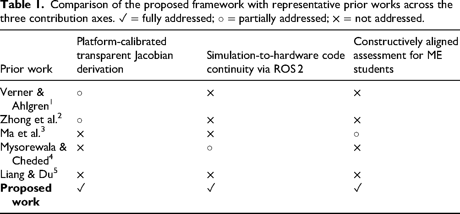
The present work addresses both limitations through three specific contributions that, taken together, distinguish it from the existing literature:
While each of the three contributions above has precedent in isolation, their simultaneous integration within a single, constructively aligned module has not been reported for Mechanical Engineering students, as summarised in Table 1. Prior frameworks that achieve simulation-to-hardware transfer—such as the FPGA-based approach of Mysorewala and Cheded
4
—do so without requiring students to derive the underlying kinematic Jacobians from first principles, relying instead on the provided motion libraries that treat the kinematic layer as a black box. Frameworks that emphasize transparent mathematical derivation, such as that of Zhong et al.,
2
typically conclude at the simulation stage and do not demonstrate code-identical deployment to physical hardware or report hardware-validated performance metrics. Constructive alignment of learning outcomes with rubric-based assessment has been advocated broadly in STEM and robotics education,
2
but has not been applied specifically to the kinematics-to-hardware pipeline for non-holonomic robots in a Mechanical Engineering program context, where the prerequisite profile—strong in engineering mathematics and classical control, with no prior robotics middleware experience—differs substantially from Computer Science or Robotics cohorts.1,2 The contribution of this work is therefore not any single element in isolation, but their combination: a module in which the same mathematical derivation, the same Python codebase, and the same rubric-based assessment instruments span theoretical derivation, simulation validation, and physical hardware deployment, validated with a cohort of final-year ME students for whom this integrated combination has been absent from the published literature.
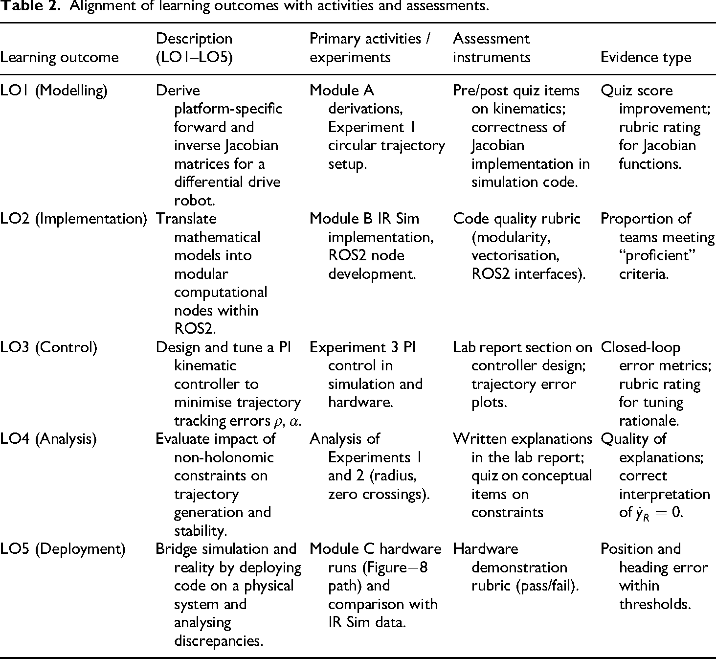
Alignment of learning outcomes with activities and assessments.
Educational methodology & learning outcomes
The curriculum adopts a scaffolded pedagogy, which is designed explicitly in such a way that students are introduced to theories of derivation, which in turn would lead to the integration of physical hardware. The method puts more emphasis on active experimentation so that abstract kinematic concepts are reinforced through feedback loops that get driven by simulations. We use the term framework as defined by Biggs and Tang,
11
who established constructive alignment as the connection between intended learning outcomes, teaching activities, and assessment instruments–the essential structure of any pedagogical framework. In the robotics education literature, the term framework has been used to describe transferable structures that can be instantiated on different platforms: Verma and Kandasamy
12
present a software framework for educational mobile robots designed for versatility across platforms; Forbrig and Wurdel
13
propose MecQaBot, a modular methodology for teaching autonomous mobile robotics that separates core pedagogy from platform specifics. Following this established usage, the present work is a framework in that it specifies a structured, transferable set of learning outcomes, instructional activities, and assessment instruments that can be instantiated on any differential drive robot without modification to the core pedagogical logic. The Ati Sherpa RP serves as a reference implementation–one concrete instantiation used to validate and reproduce the framework’s results. This is analogous to a reference system in a software framework paper. Transferability is achieved by design: the only platform-specific inputs to the entire module are the wheel radius
Target audience and prerequisites
We use the term framework in the sense established in engineering education research:1,2 a structured, transferable set of learning outcomes, instructional activities, and assessment instruments that can be instantiated on any compatible platform.
The Ati Sherpa RP plays the role of reference implementation—the concrete instantiation used to validate and reproduce the framework’s results—analogous to the role a reference system plays in a framework paper.
Transferability is achieved by design: the only platform-specific inputs to the entire module are the wheel radius
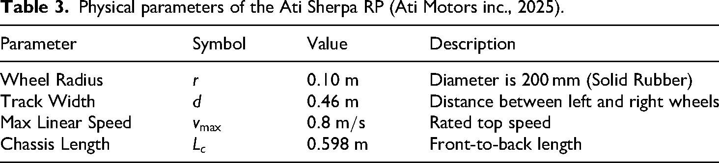
Physical parameters of the Ati Sherpa RP (Ati Motors inc., 2025).
All other elements—the kinematic derivation activities, the IR Sim simulation environment, the ROS 2 node architecture, and the assessment rubrics—are independent of the Ati Sherpa RP and transfer without modification to any differential drive robot running ROS 2. The module is intended for senior undergraduate or first–stage postgraduate students in Mechanical Engineering, Robotics, Mechatronics, or Computer Science programs. In the present study, the framework was implemented within a senior-level Mechanical Engineering Mobile Robotics elective. In the cohort studied (
Learning objectives
At the end of this course of study, participants will show the following technical skills. The alignment of learning outcomes with activities, assessment instruments, and evidence types is summarised in Table 2.
Teaching workflow and module structure
The education system is designed into three progressive units, whereby students must certify their knowledge in each level before graduating to the sophisticated level hardware installation.
Focus: Software implementation and logic validation. Activity: Students implement their derived models in Python using the IR Sim environment. This phase focuses on debugging logic errors (e.g., incorrect matrix transformations) in a risk-free environment. Visual odometry feedback allows students to “see” the math in action.
Focus: Real-world application. Activity: Validated code is deployed to the physical system. Students perform the “Figure
A natural question is whether students would benefit more from building the entire software stack from the ground up, without relying on a middleware such as ROS2. In our experience, and consistent with the cognitive-load literature on scaffolded instruction,15,16 a hybrid approach is most effective at this level. Students derive and implement all kinematic and control logic from first principles - no pre-built kinematic libraries are used, and no black-box motion primitives are provided. ROS2 serves exclusively as the communication and deployment infrastructure: it provides the publisher/subscriber transport between nodes and the hardware abstraction layer, but contributes nothing to the kinematic or control mathematics that are the actual learning objectives. Building the full ROS2 stack from scratch would redirect a substantial portion of student cognitive effort toward middleware configuration and inter-process communication, at the expense of the kinematic content, the module is designed to teach. The framework, therefore, exposes ROS2 minimally and incrementally - node interfaces, topic types, and parameter files - introduced through a focused two-hour workshop at the start of Module A (see Section 2.1), so that students engage with the software only at the level required to deploy the mathematics they have already derived.
Kinematic modeling
To be able to control the robot’s motion, the relationship between the task space (robot’s pose) and the joint space (wheel velocities) must be established.
17
The Inertial Frame
Assumptions
The following assumptions are considered:18,19
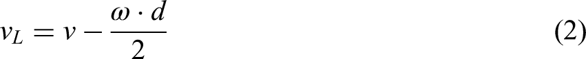
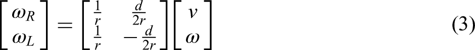
Inverse Kinematics provides the answer to this question: “If we know the desired robot velocity, how quickly should we turn the wheels?” We denote our desired robot velocity vector by 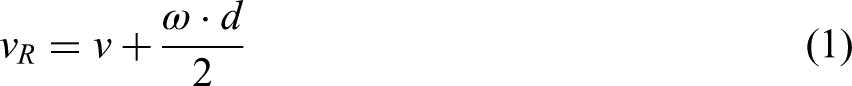
Forward kinematics (Odometry)
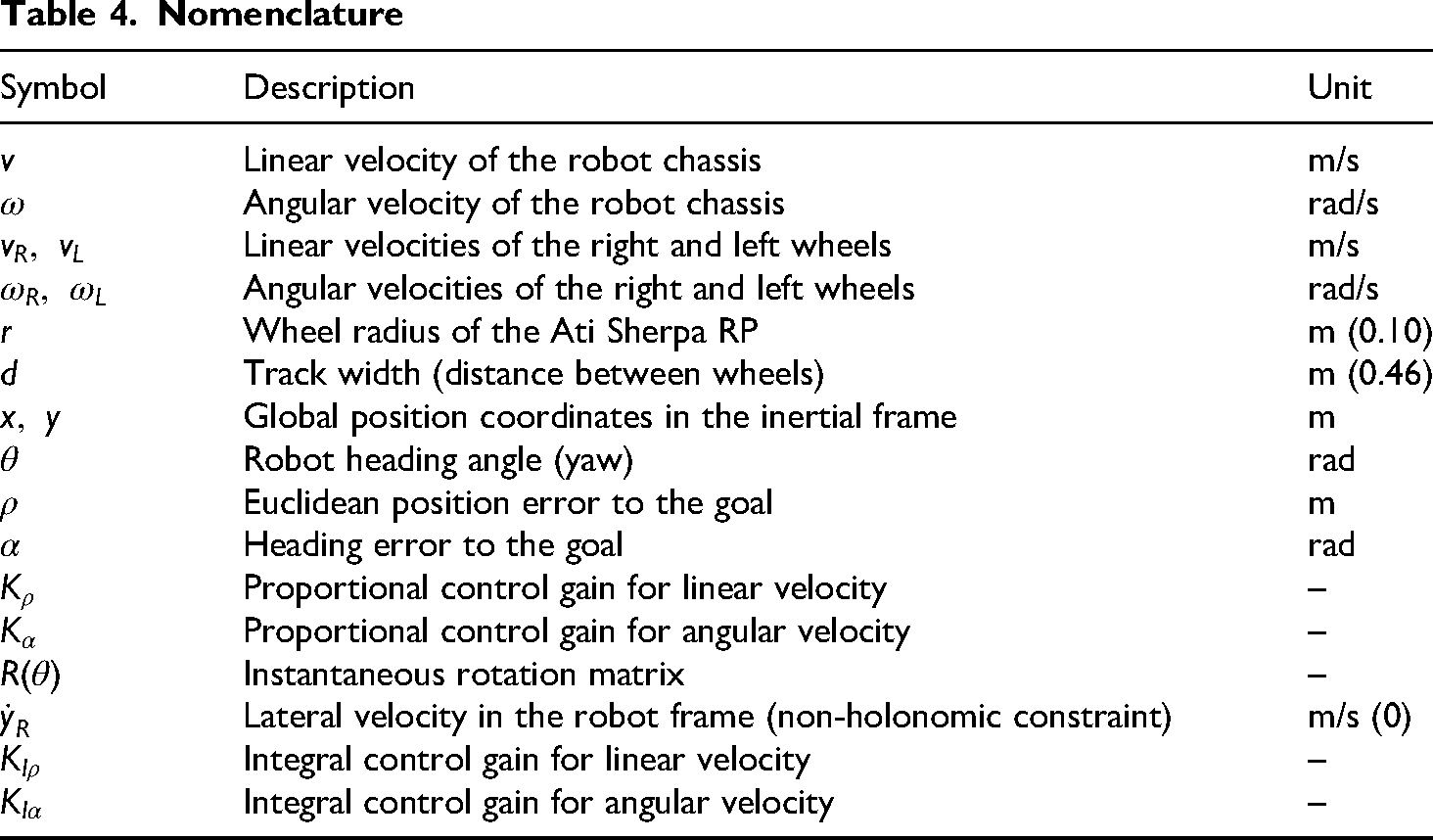
The differential drive mobile robots use a forward kinematic algorithm for odometry, which allows the robot to calculate its global position 

To convert local body velocities into global coordinates, the rotation matrix 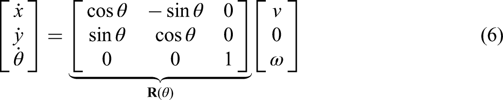
The zero second row of the velocity vector confirms that no lateral motion is possible in the robot frame, consistent with the pure-rolling and no-lateral-slip assumptions stated above. Dropping the zero lateral-velocity row (since 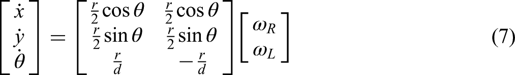
Note that the two columns of the upper
Control system design
To transition the robot from its initial position
PI kinematic controller
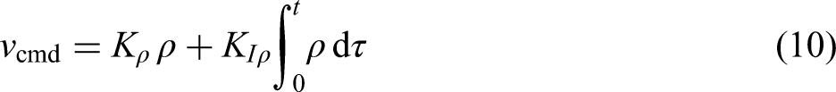
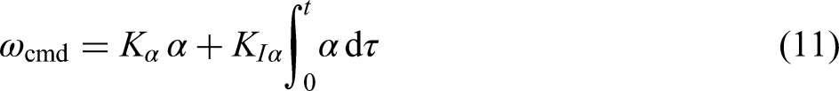
We will use a proportional–integral control algorithm to reduce the position (

Educational study design
Participants and context
The framework was implemented in a senior-level elective course on Mobile Robotics is offered within the Mechanical Engineering program. The study cohort comprised
The module constitutes a structured four-week segment of a three-credit-hour senior elective in Mobile Robotics, offered in the final year of the B.E. in Mechanical Engineering program, as a technical elective following prerequisite courses in classical control and engineering mathematics.
Data sources
To evaluate the educational effectiveness of the framework, multiple data sources were collected: (i) scores on a written quiz assessing derivation and interpretation of differential drive kinematics and non-holonomic constraints (aligned with LO1 and LO4), (ii) marks for the simulation-based lab report (LO2–LO4), (iii) performance on the hardware demonstration rubric (LO3 and LO5), and (iv) a short post-module survey capturing student self-reported confidence in applying kinematic models and deploying ROS2-based control nodes. The quiz was administered before Module A and after completion of Module C, enabling comparison of conceptual understanding before and after the experiential sequence.
Alignment of learning outcomes and assessments
Learning outcomes LO1–LO5 were constructively aligned with specific tasks and assessment components. LO1 (modeling) was evaluated via derivation items on the written quiz and through the correctness of the implemented Jacobian matrices in the simulation code. LO2 (implementation) was assessed using rubric criteria for code modularity, readability, and correct use of ROS2 node interfaces in the simulation and hardware phases. LO3 (control) and LO4 (analysis) were evaluated by examining trajectory tracking error plots, stability of the PI controller under different gain selections, and students’ qualitative discussion of non-holonomic effects in their lab reports. LO5 (deployment) was primarily assessed through the pass/fail hardware demonstration, where each team was required to navigate a predefined path within specified position and heading error bounds.
Data analysis
Quantitative data from quizzes and graded components were analyzed using descriptive statistics (mean, standard deviation) and paired comparisons of pre- and post-quiz scores to estimate conceptual gains in kinematics and control. Survey responses were analyzed using Likert-scale summaries to characterize changes in self-reported confidence, and open-ended comments were coded inductively to identify recurring themes regarding perceived benefits and challenges of the framework. This mixed-methods approach provides both numerical evidence of improved performance and qualitative insight into how students experienced the experiential learning sequence.
Educational evaluation and results
Conceptual understanding of kinematics and constraints
Pre- and post-quiz results indicated substantial gains in students’ ability to derive and interpret the kinematic relationships of a differential drive robot. The average score on items targeting LO1 and LO4 increased from 46% (
Development of implementation and control skills
Analysis of the simulation code and lab reports showed that all teams successfully implemented the inverse and forward Jacobians in the IR Sim environment and were able to generate stable circular and lemniscate trajectories. Common initial errors included missing time-step normalization in numerical integration loops and incorrect sign conventions for angular velocity; these issues were generally identified and corrected by students themselves after inspecting odometry plots and trajectory shapes in Experiment 2. By the end of the module, 28 out of 32 students achieved full marks on the rubric criteria related to correct the Jacobian implementation and properly encapsulate the kinematic logic in reusable functions, supporting LO2.
Closed-loop control performance on hardware
In the hardware deployment phase, 9 out of 10 teams met the predefined performance thresholds for the Figure
Student perceptions of the experiential framework
Survey data indicated that students’ self-reported confidence in applying differential drive kinematics in code increased from “low” or “moderate” in 72% of responses before the module to “high” or “very high” in 78% of responses afterward. Qualitative comments emphasized the value of the simulation-first approach (seeing the effect of wrong parameters immediately in the trajectory) and the satisfaction of transferring identical code to the Ati Sherpa RP without major modifications, which students associated with a stronger sense of authenticity in the lab experience. Some students noted the steep initial learning curve of ROS2, pointing to the importance of providing minimal working examples and template nodes early in the module. Overall, the data support the claim that the framework effectively bridges the gap between theoretical derivations and real-world implementation in a way that is perceived as meaningful and engaging to senior mechanical engineering students.
Instructional experiments: Ati sherpa RP as a case study platform
The validation of the framework took place through three separate experiments to enhance the theoretical foundation with programmer implementations. These three experiments aim to facilitate students’ transition from open-loop verification to closed-loop autonomous control. The following experiments use the Ati Sherpa RP as the reference platform for framework validation. The framework is inherently platform-agnostic: adopting it for a different differential drive robot requires only that the platform-specific wheel radius
System description: The Ati sherpa RP
The Ati Sherpa RP (Ati Motors Inc., Version 1.0, May 2025) is a modular mobile robotic platform designed for educational, research, and light-duty material transport applications.
29
The chassis is constructed from aluminum 2020 T-slot extrusion profiles and encased in a protective sheet-metal shell; the exposed 2020 slots provide mounting points for additional sensors or electronics. The differential drive architecture comprises two rear 200 mm cast-iron drive wheels with solid rubber tires (Shore hardness 90–95 A), each driven by a 750 W brushless DC (BLDC) motor with an integrated Twara motor driver operating at 24 V (48 V secondary mode) and a 20:1 gearbox. Two passive caster wheels (72 mm) provide frontal support. The key physical parameters used in the kinematic model are the wheel radius

System architecture of the Ati Sherpa RP platform. Hardware components (gray) interface with ROS2 middleware. Student-developed nodes (green) implement kinematics, odometry, and PI control. Provided nodes (orange) are used as-is. Dashed arrows indicate encoder feedback.
Experiment 1 – Static Trajectory (Circular Path)
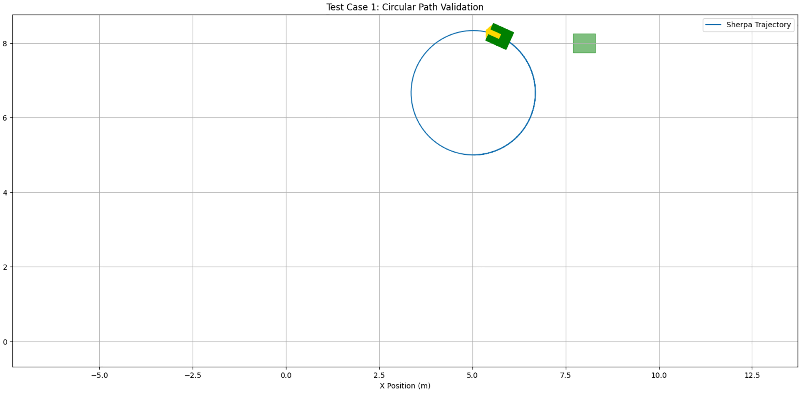
Simulation results of Experiment 1. The horizontal and vertical axes show the
Experiment 2: Dynamic trajectory (Lemniscate)
Reinforced Concept: The non-singular nature of differential drive robots through zero crossings during left-to-right turns. Common Mistakes: Students very often do not normalize their time steps (
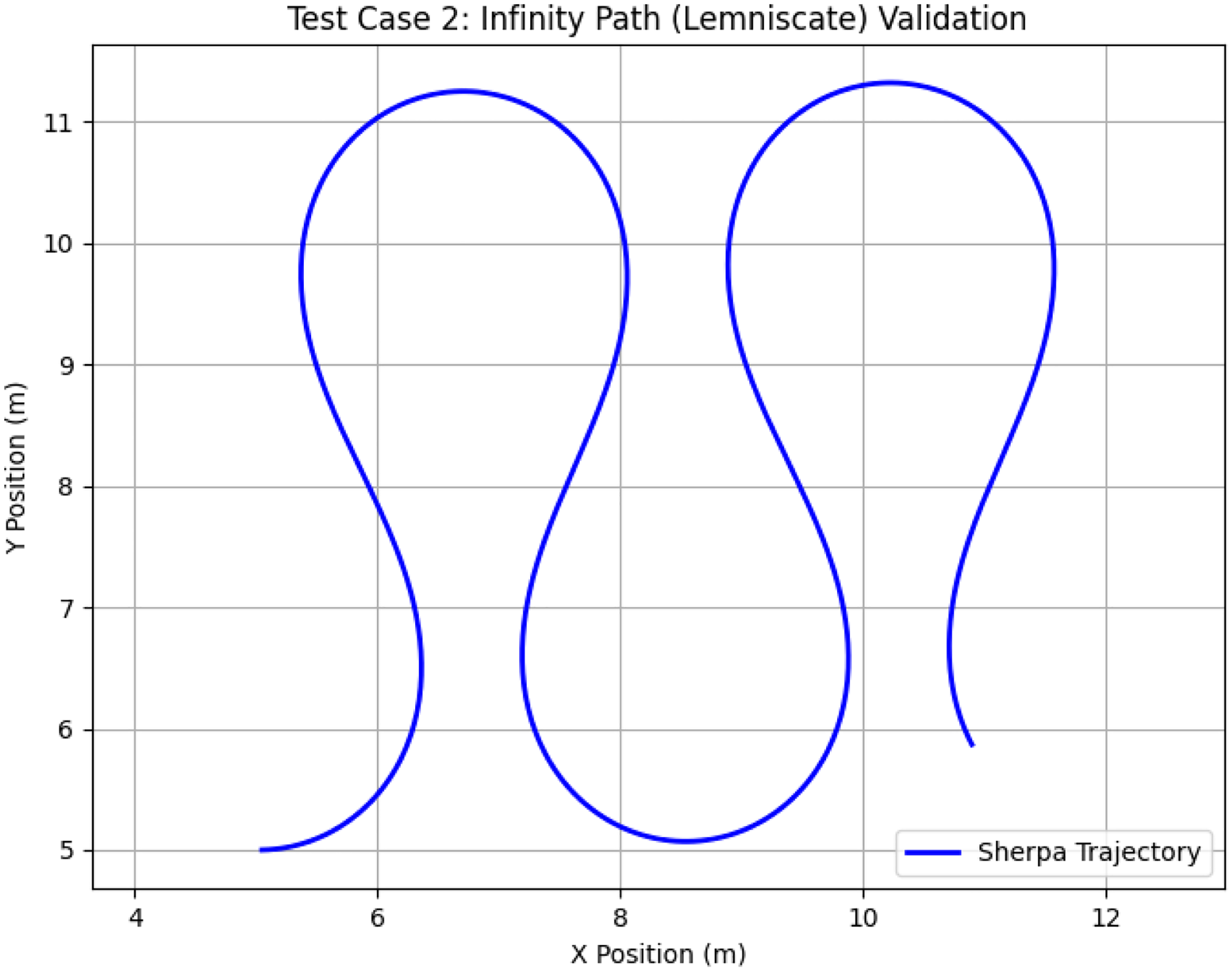
Lemniscate (Figure
Experiment 3: Autonomous goal regulation (PI Control)
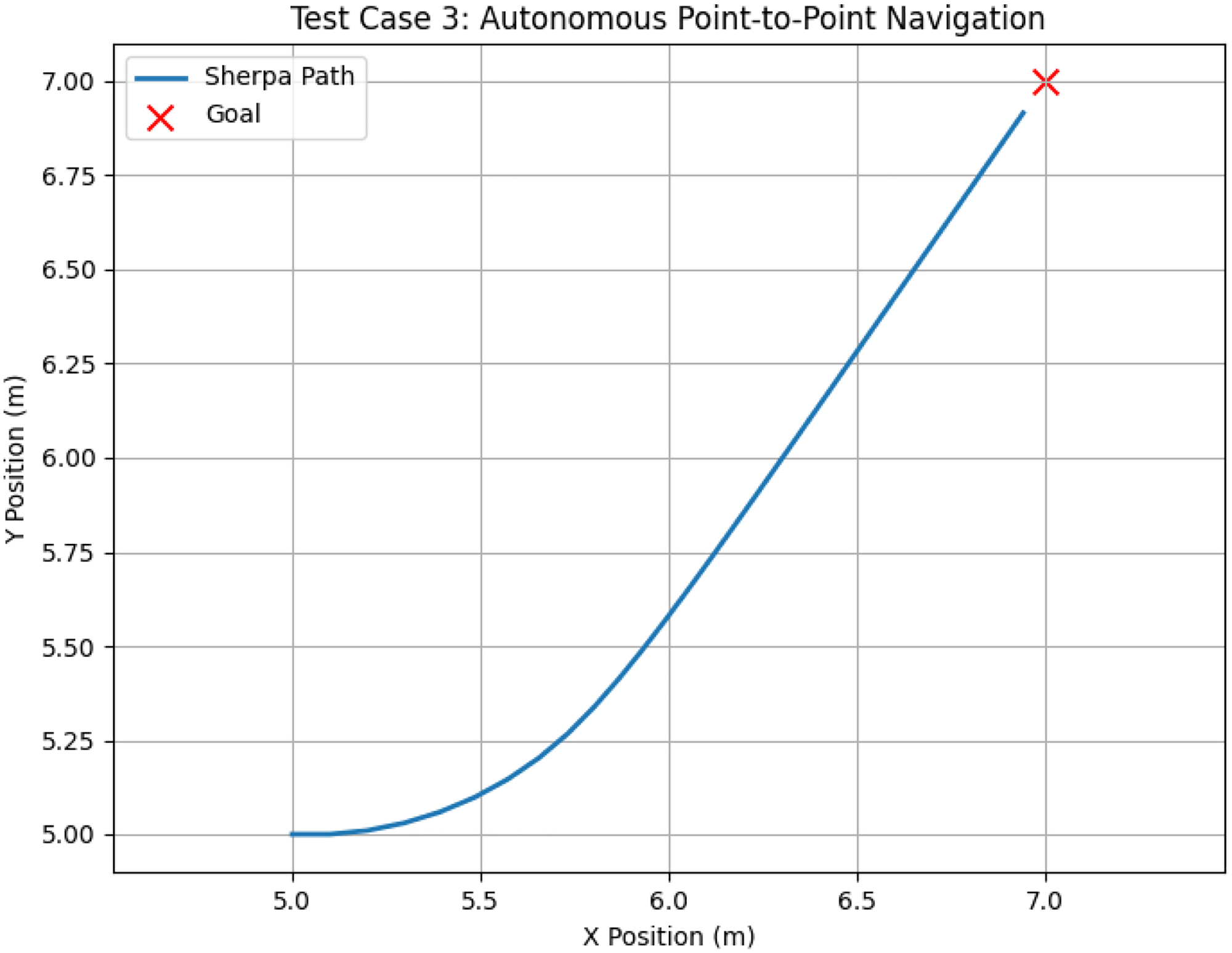
The Autonomous Navigation Results, which show that the robot first rotated to correct its heading error and subsequently drove asymptotically towards the target.
Assessment strategy
Learning outcomes of students are assessed using a mixed-method evaluation on the grounds of both applied and theoretical knowledge.
Assessment components
Grading rubric
To ensure a uniform grading process for all students receiving this guide, the following guidelines apply.
Reproducibility and open access
The framework has been designed for broad institutional adoption with minimal dependencies.
Simulation environment
System configuration
To reproduce the results presented in this paper exactly (Ati Sherpa RP, Experiment 3), the following parameter values must be established in the simulation script:
Wheel radius: Track width: Velocity limits: Proportional gains: Integral gains: Anti-windup: sign-change accumulator reset on
Suitability for remote and virtual laboratories
The construction of the software component is not directly dependent on any device drivers, which means that students can conduct their closed-loop control and kinematic simulations on a standard personal computer (regardless of operating system), using VS Code, to validate their logic before physically executing their software on the target platform’s ROS 2 middleware in the laboratory.
Conclusion
The comprehensive experiential learning framework described in this paper provides a curriculum for the instruction of a non-holonomic mobile robot kinematics and control through a case study on the Ati Sherpa RP platform. This framework also provides an integrated means of combining mathematical derivation and a structured computer simulation of robotics, thereby providing a common pedagogical link between abstract control theory and practical application. The degree of educational effectiveness of this framework is represented through the staged development of instructional simulations. In contrast to the theoretical approach of teaching kinematics and control, the use of platform-specific verification—such as the timing of the Figure of eight continuous trajectory—forces students to consider the underlying physical constraints imposed by the non-holonomic nature of mobile robots (
Footnotes
Funding
The author received no financial support for the research, authorship, and/or publication of this article.
Declaration of conflicting interests
The author declared no potential conflicts of interest with respect to the research, authorship, and/or publication of this article.
Data Availability Statement
Data sharing not applicable to this article as no datasets were generated or analyzed during the current study.