






Abstract
Understanding how head losses affect the flow configuration in hydraulic networks is essential for analyzing both natural and human-made systems, including physiological systems, biomedical devices, and urban infrastructure. In this study, a low-cost experimental system was designed and implemented to visualize and quantify the impact of both major and minor head losses on the flow distribution within a bifurcated network, using a submersible pump, ball valves, flowrate sensors, and components introducing geometric variations. Experimental results were compared with a theoretical model based on mass conservation, mechanical energy conservation, the performance curve of the pump, and correlations obtained from bibliographic data of head loss coefficients, showing good agreement. The proposed low-cost experimental setup is presented as an effective educational tool for introducing key concepts in fluid mechanics to undergraduate students, and shows how in-classroom topics are applied to a simple but real-life hydraulic configuration.
Introduction
Existing educational approaches in fluid mechanics have contributed significantly to improve conceptual understanding of fundamental topics by students. Early hydraulic design projects focused on system-level engineering calculations and infrastructure layout, but generally lacked experimental implementation and real-time validation. 1 Demonstration-based methodologies have been shown to increase students motivation and conceptual engagement, particularly for visualizing laminar and turbulent flow behavior 2 or the dynamics of waves. 3 However, these approaches are predominantly qualitative and rarely incorporate quantitative hydraulic analysis. Real-world experimental projects have highlighted the pedagogical value of connecting theory with practice, although these activities often rely on project-specific implementations that are difficult to reproduce as standardized laboratory platforms. 4 In contrast, classroom-scale experiments have successfully introduced concepts such as Bernoulli’s equation, Reynolds number, and pressure losses using simple apparatuses,5–8 yet these systems generally investigate isolated hydraulic effects rather than network interactions. Recent low-cost educational devices investigating pipe-flow parameters or Pitot-tube measurements provide accessible alternatives for teaching fluid behavior, though they are typically limited to single-line configurations or localized measurements.10–12 In this work, a low-cost experiment, easy to implement under laboratory conditions, is presented, which allows to perform a quantitative analysis of the flow through an hydraulic network, and to compare with the correponding theoretical predictions.
Thanks to the smartphone revolution and the rise of open hardware platforms, low-cost of sensors, microcontroller units and other electronic components are now accessible for educational purposes. In addition, curriculum-oriented reforms integrating sensors, data acquisition, and inductive learning have demonstrated the importance of modern instrumentation in fluid mechanics education. 9 Reproducible low-cost engineering education platforms have demonstrated the value of combining construction methodology, instrumentation, and experimental validation. The regular incorporation of these new technologies into the teaching of fluid mechanics can help students to strengthen the acquired knowledge and to observe its practical application. The experimental setup that is introduced in this article, includes the employment of flowrate sensors and their digital instrumentation.
In particular, hydraulic head loss is a fundamental concept in fluid dynamics, as it represents the reduction of useful mechanical energy, due to friction and flow disturbances within a conduit. Although this phenomenon is routinely addressed in theoretical coursework, students often lack opportunities to observe its consequences in practical settings, particularly in the context of flow distribution in networks and branched systems. The relationship between flowrate and head loss, specifically at branches located downstream from a bifurcation, determines the behavior of flows in many human-made and natural systems. These includes: (1) biological systems, such as cardiovascular or respiratory networks13,14; (2) urban infrastructure, such as water supply and sewerage networks 15 ; (3) residential hydraulics 16 ; and (4) biomedical devices, in which fluids are employed or transported. 17 Despite its importance, this topic is often underrepresented in practical undergraduate courses of different professional degrees, including physics, chemistry and engineering. To address this issue, we propose a simple and accessible experiment, enhanced with basic digital instrumentation, to help students understand how head loss or pressure drop generated by a pipe component (for instance, a valve or a joint) affects the overall flow configuration in an hydraulic network. The objective is to provide a low-cost, hands-on experimental setup, as an educational tool to illustrate how flowrates in a network respond to changes in component-induced resistance.
An experimental setup was built, consisting of a simple flow circuit with one bifurcation, two valves, two flowrate sensors, and a coupling. The working fluid(water at room temperature) is taken from a reservoir with a submersible pump, circulates through the network, and is discharged back into the same reservoir. The experimental results are compared with predictions from a theoretical model, based on mass conservation, mechancial energy conservation and the performance curve of the pump. Empiric expressions to quantify head losses of the components are also considered. This hands-on approach strengthens students’ understanding of fundamental principles in fluid dynamics and demonstrates their relevance in both natural and engineered systems.
Experimental setup
Flow circuit
The proposed flow circuit is shown in Figure 1. A pump, immersed in a water reservoir, provides a constant volumetric flow
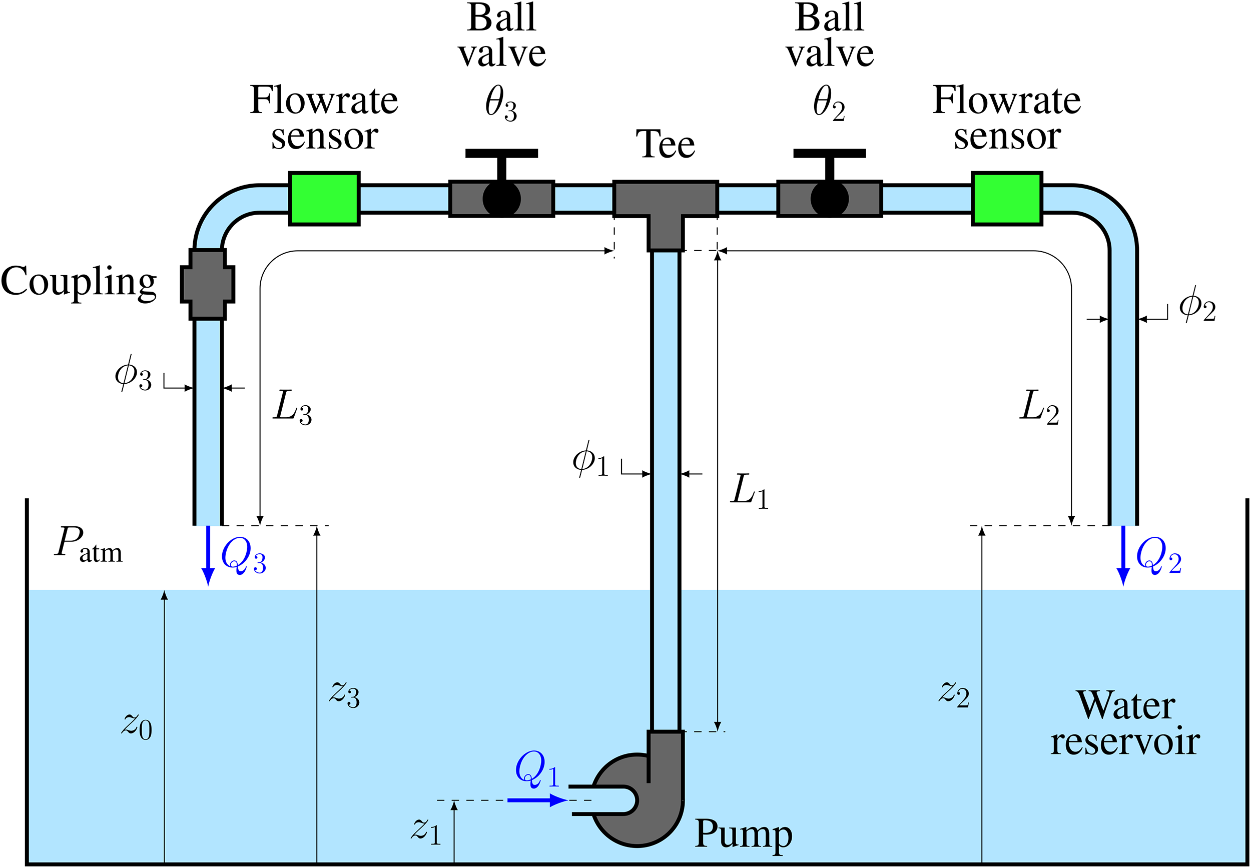
Scheme of the flow circuit proposed for the experiment. Variables and parameters are explained in Section “Flow circuit”.
Equipment and cost
The components used in the actual experimental setup are shown in Figure 2. Reservoir, submersible pump, tee joint, ball valves, flowrate sensors, and coupling were placed in the flow circuit as depicted in Figure 1. Both sensors were connected with Dupont cables to a protoboard and an ESP32 module, which was in turn connected to a computer with a USB cable, as illustrated in Figure 2g. An electronic balance and a graduated cylinder were also employed during the calibration procedures of the flowrate sensors.
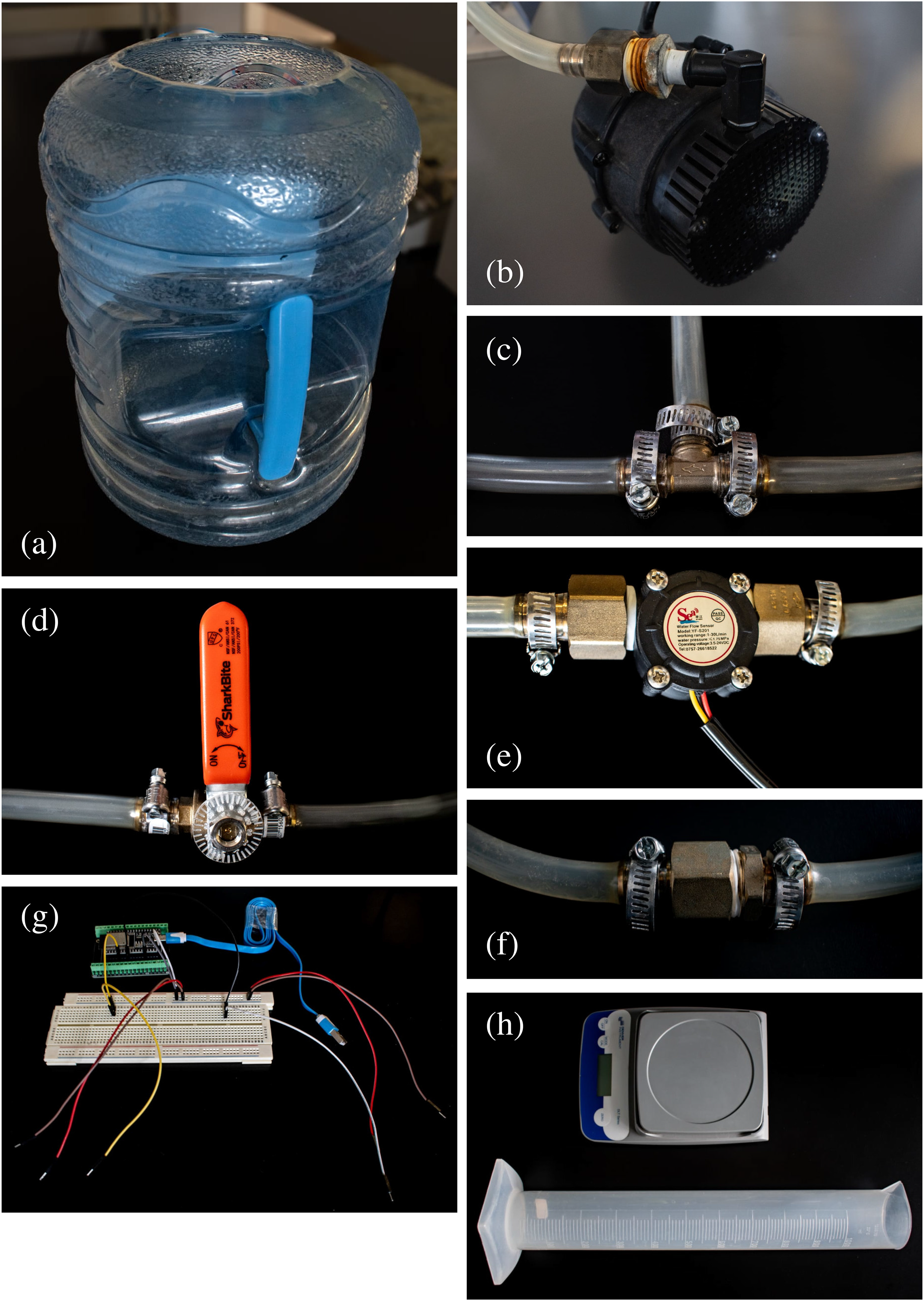
Photographs of the main components of the experimental setup: (a) water reservoir, (b) submersible pump, (c) tee joint, (d) ball valve with goniometer, (e) flowrate sensor, (f) coupling, (g) ESP32 module with protoboard and cables, and (h) electronic balance and graduated cylinder.
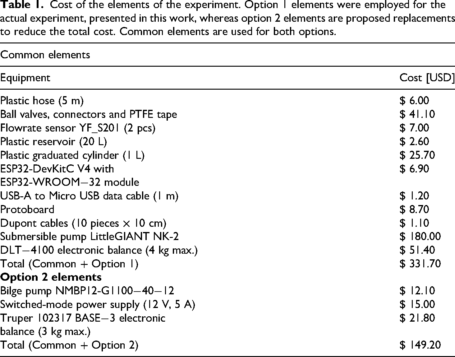
The cost of the experiment, separated for each of its components and gathered for the total, is presented in Table 1. They correspond to the USD equivalents of the local costs of the components and total. The componets used in the actual experiment correspond to the combination of Common elements and Option 1 elements, while a lower cost alternative is given by substituting Option 1 elements by Option 2 elements. All the components can be obtained through e-commerce sites, such as AliexPress or Amazon, besides local distributors.
Cost of the elements of the experiment. Option 1 elements were employed for the actual experiment, presented in this work, whereas option 2 elements are proposed replacements to reduce the total cost. Common elements are used for both options.
Theoretical model
Considering the aforementioned configuration (see fig. 1), considering a steady state system and an incompressible fluid, mass conservation dictates that:


Major head losses
A major head loss 





Minor head losses
A minor head loss 
For instance, for an insert (or threaded) tee joint, in a symmetric configuration for dividing a stream, 
In turn, considering a ball valve at the 

The loss coefficient of a flowrate sensor of paddle-wheel type,16,19 such as the ones employed in this experiment, is usually very low, since it does not present a permanent obstruction to the flow. Consequently, for this model, we neglect its contribution to the minor head losses.
Finally, the loss coefficient of a coupling, formed by a sudden expansion and an immediate contraction, placed very close to each other, is obtained as 3 times the addition of the empiric relations for the expansion and the contraction, obtained from experimental data,
21
correspondingly given by:


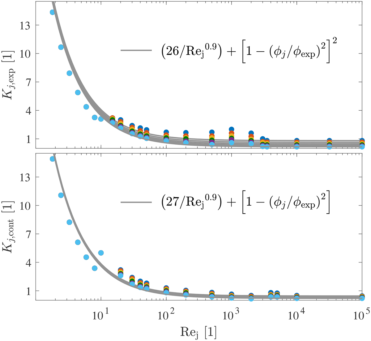
Head loss of a sudden expansion
Therefore, the sum of major and minor head losses, for the flow circuit depicted in Fig. 1, are given by:

Details on essential components
Submersible pump
A submersible pump (LittleGIANT model NK
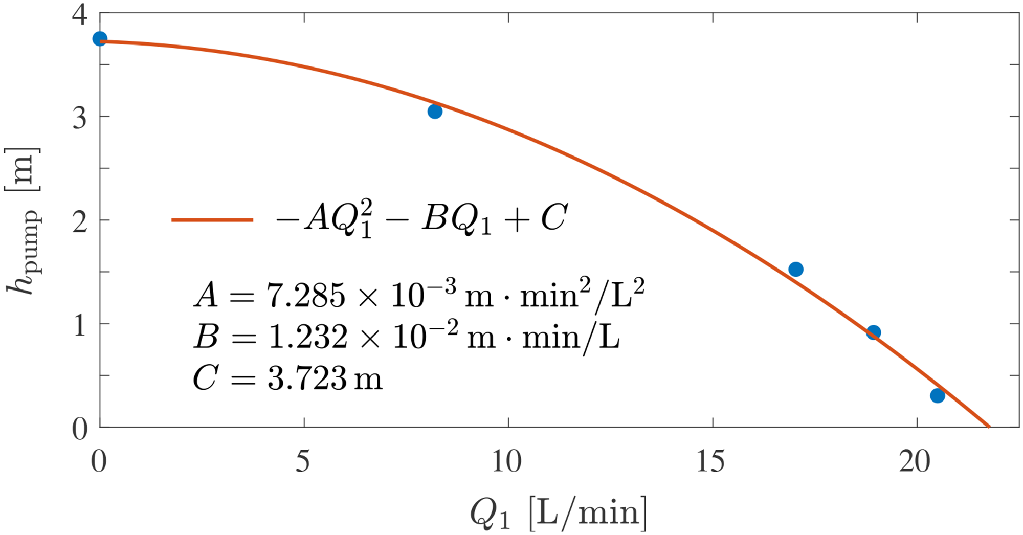
Flowrate sensors
Two low-cost flowrate sensors YF_S201, paddle-wheel type which operation is based on a rotating mechanisms that employs the Hall effect, 18 were employed in this work. The application and reliability of this kind of flowrate sensors has been successfully tested for water consumption measurements,23–25 leakage detection,26,27 and monitoring of waterways.28–30
Volumetric flowrate
The mass flowrate 
Also, the mass flowrate can be obtained from the measurement of the accumulated mass 

Digital signal
The YF_S201 flowrate sensor has a multi-pole magnet attached to a rotating element, a paddle-wheel that is driven by the crossing fluid. A Hall effect probe sends a step signal (low-high) according to the polarity (positive-negative) of the magnet that is close to it. The signal from the sensor is sent to a microcontroller unit ESP32, through one of its analog-to-digital converter (ADC) pins. From the step signal, we can define a pulse, each time the signal rises from low to high, and we can count the number of pulses 
Calibration
Since the angular velocity of the rotating element in the sensor is related to the flowrate that goes through it, then the frequency 
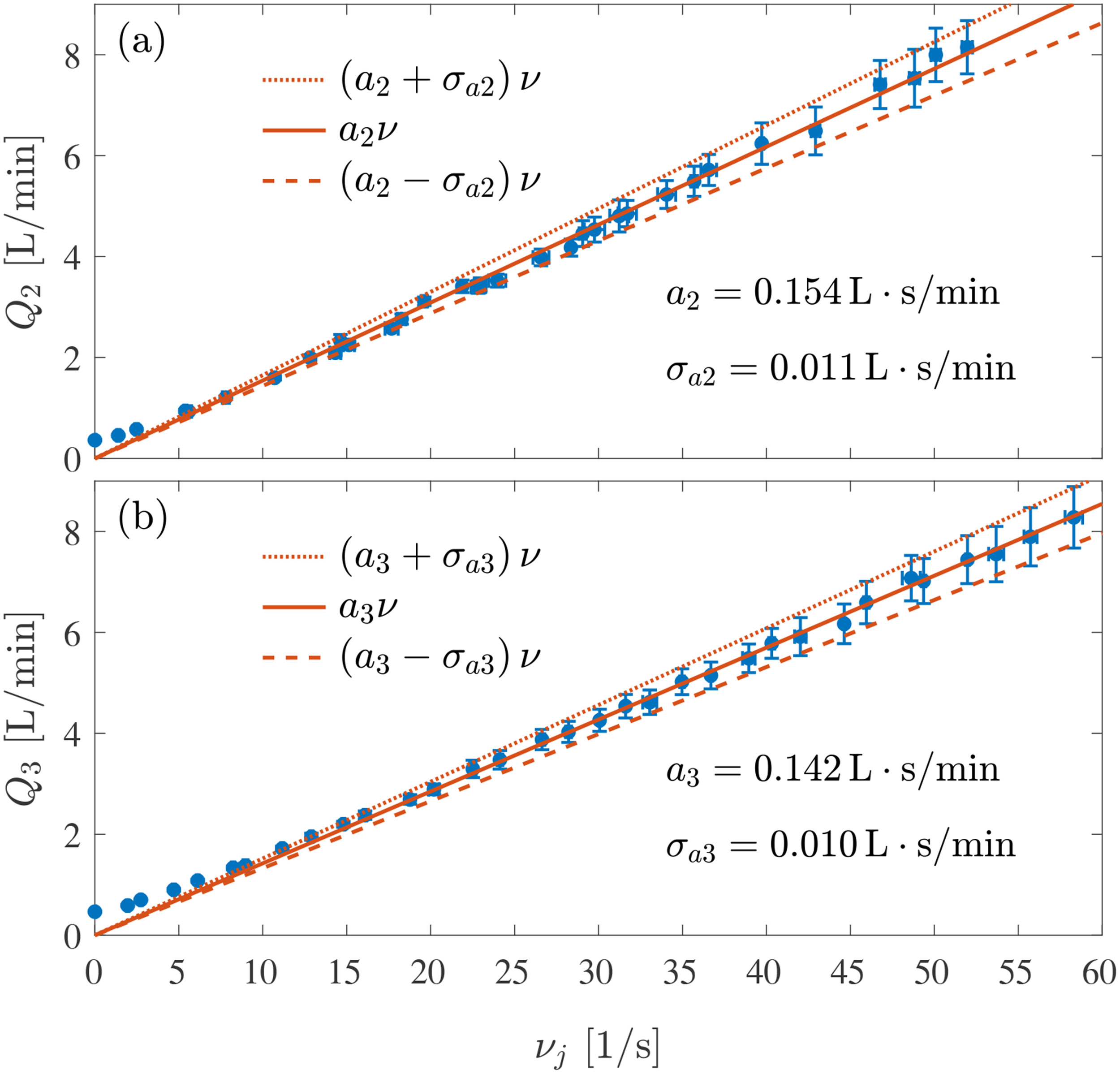
Calibration curves of the (a) YF_S201 flowrate sensor in the
Implementation and example results
The whole flow circuit was built with the same kind of pipe, therefore one can consider a single inner diameter
The simultaneous solution of eq. (1) and eqs. (3), one for 


Examples of the behavior of the system are presented in Figure 7. The angle
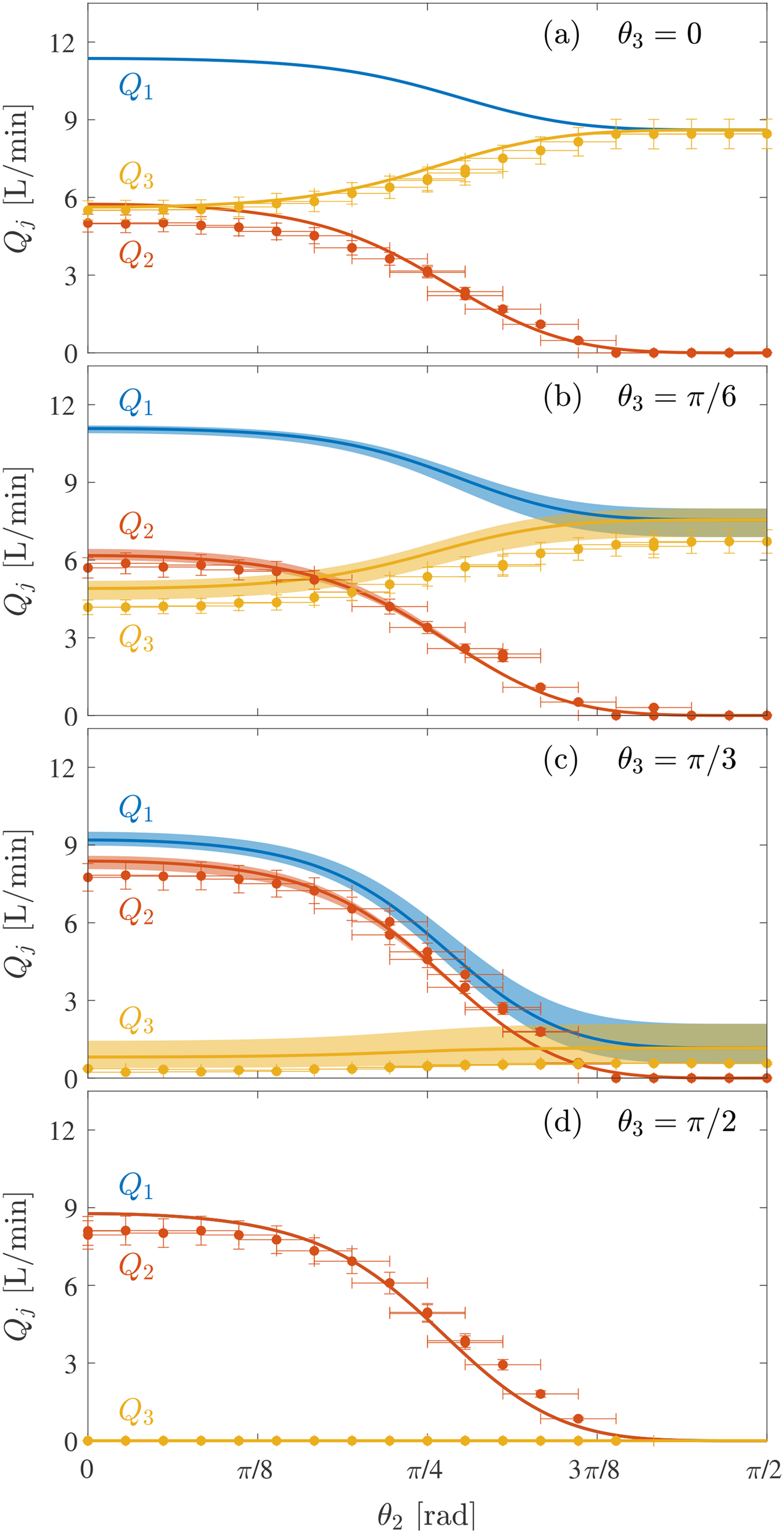
Volumetric flowrates
As it can be observed in Figure 2(d), a goniometer (made of acrylic) was incorporated to the handle of each ball valve. The resolution of the goniometer is
In Figure 7, for each subfigure corresponding to a fixed angle
For a fixed angle
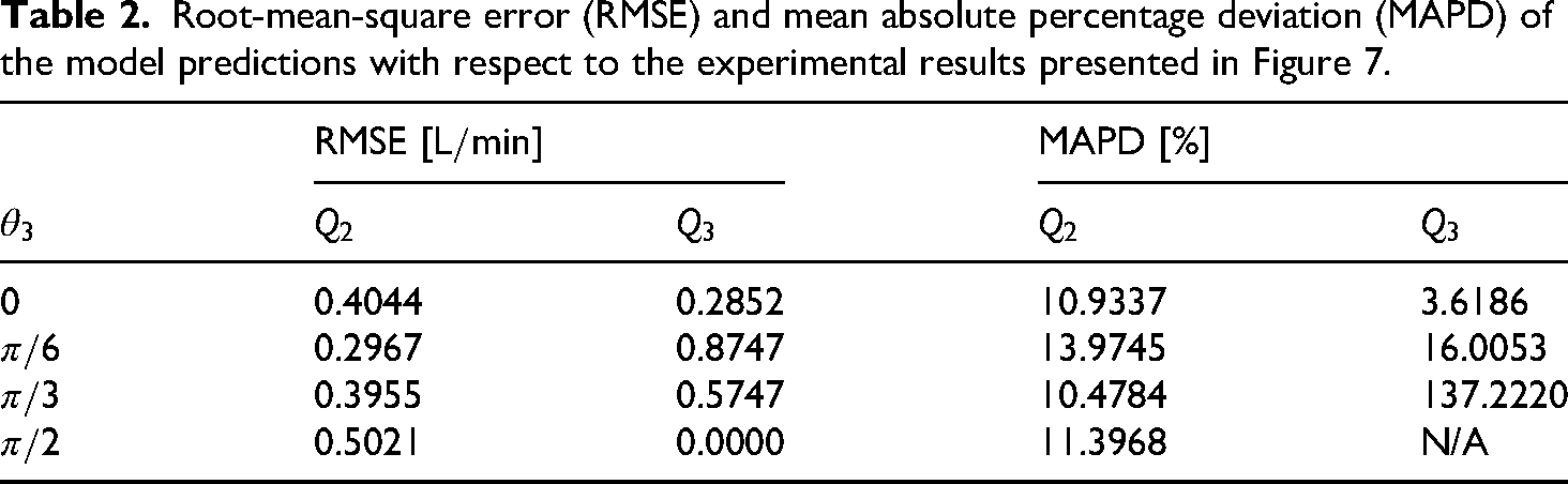
Statistical metrics, for the example results presented in Figure 7, are given in Table 2. For instance, the Root-Mean-Square Error (RMSE) is smaller than
Root-mean-square error (RMSE) and mean absolute percentage deviation (MAPD) of the model predictions with respect to the experimental results presented in Figure 7.
Discussion
As it can be observed in Figure 1, both branches discharge at a position sligthly above the surface of the water reservoir. Thus, the head loss measured from the entrance of the tee joint to the discharge (at atmospheric pressure) must be equal for both branches. This statement can be analyzed with equations as follows. Taking eq. (2) to write eq. (11) in terms of 
Now, following almost the same math procedure as before, but instead of eliminating 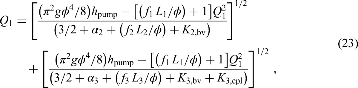
Despite the fact that theoretical results follow similar trends to those of the experimental measurements, there are notorious differences among them. An important source of errors comes from the employment of correlations, that were developed from the data available in the bibliography for the loss coefficients of the components that generate minor head losses.16,19,21 Particularly, we have to mention the cases of the tee joint and the ball valve. The correlation employed for the coefficient
Additional sources of error may arise due to conditions not considered in this work, such as curved pipe paths, which undoubtedly contribute to head loss, and uneven vertical positions of branch discharges above the surface of the water reservoir. Although we attempted to minimize the effects of these situations, they certainly contribute to the discrepancies observed between the experimental results and the theoretical predictions.
Finally, we have to mention that we have performed the calibration of the flowrate sensors, since there is a lack of information, which should have been provided by the manufacturer. The advantage of finding low-cost components comes with a negative consequence, since the corresponding datasheets may not be accurate or include a complete description of the functioning of the devices. Nevertheless, we believe that the exercise of calibrating sensors may present benefits for the students, since they represent a crucial step to obtain rigorous experimental data.
Educational implementation
The low-cost components and the simple flow network proposed for this experiment makes it particularly useful for educational purposes in undergraduate courses, within the curricula of physics, chemistry and engineering degrees. By allowing the student to adjust head losses and measure the resulting flowrates, this hands-on experiment provides a useful platform for teaching and learning fundamental fluid mechanics principles, such as mass and mechanical energy conservation. This approach encourages active learning 35 and the use of digital instrumentation, 36 providing a clear example of how theoretical fluid mechanics are applied on a practical situation.37,38
The experiment proposed in this paper allows to study and analize the flow configuration in a simple flow network, with a bifurcation. During the laboratory activity, the professor should show the components of the flow circuit and let students deduce their function. A quick glimpse of the flow bifurcation at the tee joint must lead to a deduction of the mass conservation principle. Following the path of a volume element departing from the resevoir, driven by the pump through the mainstream and the tee-joint, going through one of the branches and its components, and being discharged at the surface of the resevoir, helps to infer the mechanical energy conservation principle. Emphasis must be done on the role of ball valves and flowrate sensors, giving a brief explanation on the physical mechanisms that enable their operation. As well, the professor must describe the performance curve of the pump, focusing on the adjustment of the hydraulic head that it can provide for a given flowrate, and vice versa. After the laboratory activity, the experimental results should be compared to the theoretical curves, deduced from mass conservation and mechanical energy conservation. The theoretical results can be easily obtained by means of software with a solver for nonlinear algebraic system of equations, which can be considered as a take-home project for students. These actions will guide students towards an understanding of the effect of hydraulic head loss and its effect on the flow configuration. For instance, they will deduce how the distribution of flowrates in the branches only depends on the hydraulic resistance configuration at both branches, whereas the total flowrate at the mainstream must obey the performance curve of the pump, as a consequence of the pump-system interaction.
A student questionnaire has been developed to support the educational objectives of the proposed experiment, which is presented as supplementary material. Its main purpose is to evaluate students’ understanding of key concepts explored in the experiment, such as mass and mechanical energy conservation, major and minor head losses, and energy injection by a pump. The questionnaire also encourages critical thinking about the experimental procedure, potential sources of error, and improvements that can be done. It also serves as an assessment tool for the active learning approach, enabling educators to evaluate students’ engagement, comprehension, and the effectiveness of the experiment.
Conclusions
Most existing educational systems focus on isolated concepts, qualitative demonstrations, or simplified flow configurations. Several studies provide low-cost or experimentally accessible platforms; however, few integrate controllable hydraulic resistances, quantitative measurements, and theoretical-experimental comparisons within an hydraulic network. In particular, current educational setups rarely allow students to investigate how competing head losses influence flow redistribution between parallel branches, despite this being a fundamental concept in hydraulic systems analysis. This limitation highlights an important gap in fluid mechanics education, particularly in laboratory environments intended to connect theoretical modeling with measurable hydraulic behavior. The present work addresses this issue through a modular, low-cost experimental setup that integrates a bifurcated pipe network, adjustable hydraulic resistances, digital flow monitoring, and predictive hydraulic modeling. Unlike previous educational systems, the proposed implementation enables students to quantitatively analyze the interaction between major and minor losses, pump-system response, and branch-dependent flow distribution within a reproducible and digitally instrumented laboratory framework.
Its application is suitable for undergraduate stdents from different disciplines, including physics, chemistry, and engineering.
The experiment provides fluid mechanics professors with a tool to introduce and explore:
the mass conservation principle, the mechanical energy conservation principle, the performance curve of a pump, and the effect of hydraulic head loss on the flow configuration of a network.
Additionally, a theoretical model has been developed, using generic correlations to calculate head losses, to estimate the mainstream and branches flowrates, for a given combination of opening angles of the two ball valves, each located at one of the two pipes outgoing from the bifurcation. This theoretical framework, despite its simplicity, provides students with trend curves to compare with the experimental results, and observe the effect of the network parameters and the pump-system interaction over the flowrates and the hydraulic head provided by the pump. Nevertheless, in order to reduce errors, particular behavior curves for each component of the network must be obtained instead of using the generic correlations. As well, it is advisable to perform a calibration procedure, whenever low-cost sensors are employed.
Supplemental Material
sj-pdf-1-ijj-10.1177_03064190261463316 - Supplemental material for A low-cost experiment to understand hydraulic head losses and their effect on flowrates in a network
Supplemental material, sj-pdf-1-ijj-10.1177_03064190261463316 for A low-cost experiment to understand hydraulic head losses and their effect on flowrates in a network by René Ledesma-Alonso and Benito Juárez-García in International Journal of Mechanical Engineering Education
Footnotes
Acknowledgments
We thank Gustavo Armendariz Peña for his support in taking the photographs of the equipment. We acknowledge the Laboratorio Nacional de Soluciones Biomiméticas para Diagnóstico y Terapia (LaNSBioDyT) of the Facultad de Ciencias UNAM, for providing access to its facilities and the technical support from its staff.

Funding
The authors disclosed receipt of the following financial support for the research, authorship, and/or publication of this article: This work was supported by the Programa de Apoyo a Proyectos de Investigación e Innovación Tecnológica (PAPIIT) of the Universidad Nacional Autónoma de México (UNAM), through the project grant IA105124.
Declaration of conflicting interests
The authors declared no potential conflicts of interest with respect to the research, authorship, and/or publication of this article.
Data availability statement
Data sharing not applicable to this article as no datasets were generated or analyzed during the current study.
Supplemental material
Supplemental material for this article is available online.
References
Supplementary Material
Please find the following supplemental material available below.
For Open Access articles published under a Creative Commons License, all supplemental material carries the same license as the article it is associated with.
For non-Open Access articles published, all supplemental material carries a non-exclusive license, and permission requests for re-use of supplemental material or any part of supplemental material shall be sent directly to the copyright owner as specified in the copyright notice associated with the article.
