
Abstract
The two-bladed rotor is one of the promising concepts to emerge from the study of super large wind turbines. However, the rotor is prone to generating larger vibrations compared with conventional three-bladed rotors. In particular, in-plane vibration is hard to avoid because its damping is small. Furthermore, blades are becoming more flexible as wind turbines are getting larger. In-plane self-excitation of a 10-MW wind turbine with a two-bladed rotor was studied in this article through aero-elastic simulations. This study shows that even if the blade deformations are almost the same, large rotor in-plane self-excitation does not occur in a three-bladed rotor; however, it does occur in a two-bladed rotor. The self-excitation was shown to be caused by a combination of blade in-plane elasticity and gravity. Furthermore, the mechanism was theoretically demonstrated through simplified models that showed a mass and a spring.
Introduction
Renewable energies are necessary for a sustainable society. Wind energy is the most commonly utilized source because it is more economical than other alternatives (Global Wind Energy Council, Greenpeace International, 2012).
Several multi-megawatt (MW) offshore wind turbines have been developed, and research and development has been continuously conducted (European Wind Energy Association, 2011; Jensen and Natarajan, 2014). Cost reduction by a mass reduction via a load reduction is one of the important aspects in addition to the structural integrity of the turbine.
There were several types of rotor configurations in the early days of commercial wind turbines in the 1980s-1990s. The two-bladed turbines had some problems. The higher rotor speed of two-bladed rotors tends to generate more noise compared with three-bladed rotors, and two-bladed rotors are less favored because their rotation looks uneven, particularly when viewed from the side. Furthermore, the vibrations of two-bladed rotors tend to be larger than those of three-bladed rotors. These aspects have made two-bladed rotors less competitive in the onshore market; with a limited number of exceptions, the rotors disappeared from use (Vergnet Wind Turbines, 2014; Windflow Technology, 2014). However, the situations were changed, and some of the features of two-bladed turbines began to receive attention in the offshore market. Some large-scale two-bladed wind turbines are being developed (2-B Energy, 2010; De Vries, 2012) with the aim of a lower cost of energy.
The blade cost share is large for wind turbines. Rotors with smaller numbers of blades are promising to reduce the cost of the wind turbine. Furthermore, the higher rotational speed of the two-bladed rotor is advantageous to the drive train design because it requires a lower gear ratio and rotor torque. The noise issue is more acceptable offshore because noise restrictions are less strict there. Therefore, the rotor speeds of offshore wind turbines are slightly higher than those onshore, and the high rotor speed of two-bladed rotors is thought to be acceptable.
Transportation and installation are heavily dependent on weather and marine conditions. The two-bladed rotors are advantageous to shorten the offshore operation period in transportation and installation because most of the components can be assembled onshore.
Blade eigen-frequencies are designed slightly higher than the blade passing frequencies to reduce the excitation. In other words, the blade’s eigen-frequencies vary in correspondence with the rotor speed. In particular, the edgewise eigen-frequency is important because the aerodynamic damping is small and hard to improve with controllers.
There are two major types of two-bladed rotors: teetered and rigid. The former allows differential motion using a teeter hinge at the hub (Gipe, 1995). Because they can effectively reduce differential loads, teetered rotors are the most popular concept for two-bladed wind turbines up to 1 MW. However, the complex mechanism has disadvantages in reliability and serviceability. Furthermore, sophisticated wind turbine controllers have been effective in reducing the load reduction. Therefore, teetered rotors are less popular for multi-MW concepts. Considering the situation above, the present research is focused on a rigid rotor, which is more promising for large-scale offshore wind turbines.
Wind turbine rotors are sometimes compared with helicopter rotors as large rotational structures. The latter rotates in almost a horizontal rotor plane at high rotational speed. Therefore, the effects of the gravity force are steady, and centrifugal force affects much of the condition. However, the former rotates in a perpendicular rotor plane at a low rotational speed. In this condition, the gravity term is predominant and provides cyclic excitation. Therefore, the elastic behavior of the wind turbine rotor is quite complicated. Various parametric vibrations in wind turbine rotors are summarized in Kodera (2010). Comprehensive aero-elastic topics in wind turbine blades are summarized in Hansen et al. (2006). Furthermore, the vibrations are more significant and important as the blades become larger and more flexible. The stiffness is the most important of several design requirements of large-scale wind turbine blades.
Larsen and Nielsen (2007) analyzed the nonlinear parametric instability of a wind turbine blade based on a 2-degree-of-freedom model with blade flapwise and edgewise directions. The stability boundaries were determined as a function of the amplitude and frequency of the support point motion, the rotational speed, damping ratios, and eigen-frequencies. Li et al. (2013) analyzed in-plane motion of a wind turbine blade under the combined actions of parametric and forced excitations. The effects of gravity, structural damping, and geometric nonlinearity were included in the mathematical model. The influences of structural damping, perturbed amplitude, and the frequency of the rotating speed on blade behavior were discussed. Ramakrishnan and Feeny (2012) analyzed a forced Mathieu equation with cubic nonlinearity for the dynamic behavior of a wind turbine blade using the method of multiple scales, which showed super-harmonic and sub-harmonic resonances for different orders. All of the research above focused on the individual blade, and influences on the rotor behavior were not discussed.
Considering the situations mentioned above, the following studies were conducted in two- and three-bladed rotors with respect to in-plane parametric excitations:
Aero-elastic models were defined in two- and three-bladed rotors (section “Outlines of aero-elastic simulations”).
Aero-elastic simulations were conducted to validate the in-plane excitation and responses on each configuration (sections “Aero-elastic simulation results” and “Simple model aero-elastic simulations”).
Simplified mass–spring models were derived for elastic rotors to make the excitation mechanism clear. Furthermore, the stability and loads were calculated, and perspectives for large-scale two-bladed wind turbines were discussed (section “Spring–mass model”).
Outlines of aero-elastic simulations
Aero-elastic simulations were conducted to validate the in-plane vibration of two- and three-bladed rotors using BLADED. The code applies multibody dynamics for the rotor and tower structure models, and blade–element and momentum methods are used for aerodynamics. Furthermore, blade pitch and generator torque control are also taken into account. Therefore, it is sufficient to evaluate the blade deformation and the effects of gravity in this study.
Wind turbine model
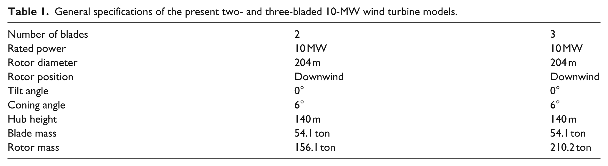
The outlines and general specifications of the present two- and three-bladed 10-MW wind turbines are shown in Figure 1 and Table 1. The same blade, shown in Figure 2, was assumed for both rotors. Parameters of tower shadow model of the downwind turbines were determined based on Yoshida (2006).
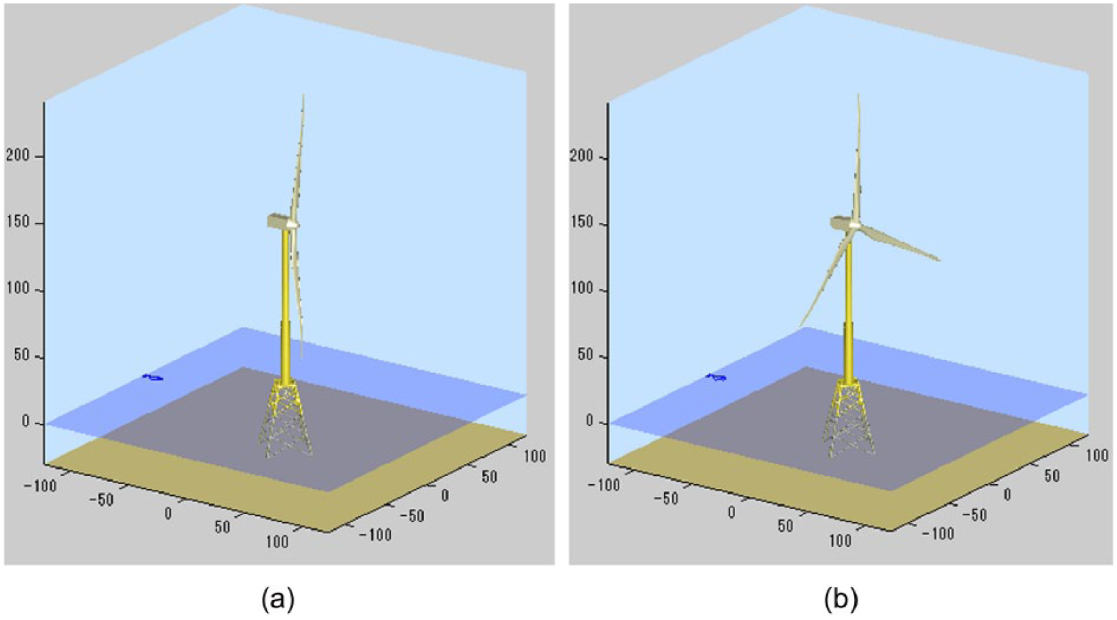
10-MW wind turbine model at 0° rotor azimuth angle: (a) two-bladed rotor and (b) three-bladed rotor.
General specifications of the present two- and three-bladed 10-MW wind turbine models.
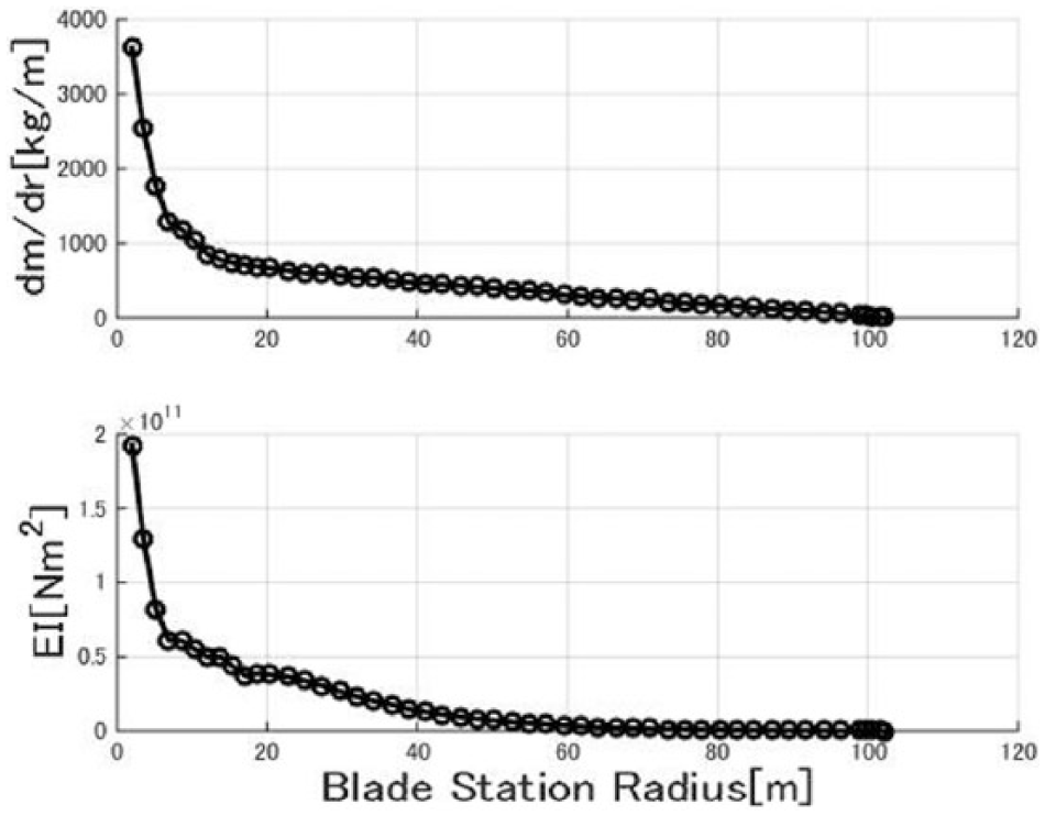
Distributions of the blade mass and in-plane stiffness.
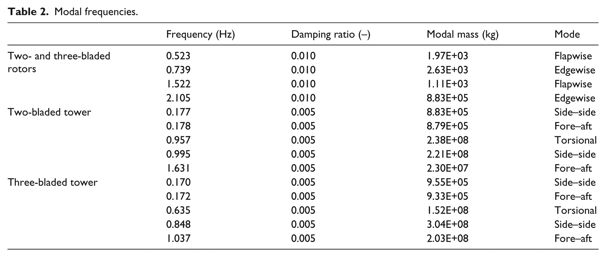
The vibration characteristics, such as the eigen-frequencies, structural damping factors, and modal mass, are shown in Table 2. The difference in the number of the same blade results in the difference in mass of the rotor–nacelle assembly and the tower eigen-frequency, and the drive train was assumed to be rigid.
Modal frequencies.
Wind turbine control is necessary for aero-elastic simulations. However, variable-speed pitch control parameters were determined based on Yoshida (2011); simulations were conducted only in cases of the optimal mode fixed pitch conditions.
In addition to the conditions above, 10 kg of additional mass was applied at the tip of blade 1 as mass imbalance, and +0.3° and −0.3° of pitch misalignments for blades 2 and 3 (in case of the three-bladed rotor) were applied for the rotor aerodynamic imbalance.
Analysis conditions
Simulations were conducted under the optimal mode operation to avoid the effects of the blade pitch control. The Kaimal model is assumed for an 8-m/s average wind speed and 17.4% (category C; International Electrotechnical Commission, 2005) turbulence intensity, which is appropriate for large-scale offshore wind turbines. The time histories of the wind speed and direction at the hub center are shown in Figure 3. The average wind shear exponent was 0.14, and the nacelle direction was 0°. The durations and sampling times of the simulation were 600 and 0.05 s.
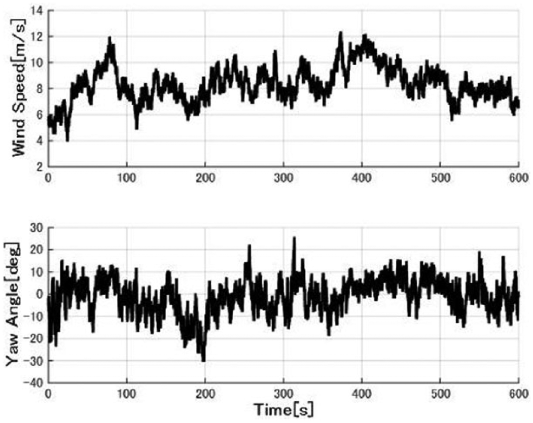
Time history of the wind speed and direction at the hub.
Aero-elastic simulation results
General characteristics
The time histories of the rotor speed are shown in Figure 4. Although the power is similar to that of the three-bladed rotor, the two-bladed rotor rotates 25% faster than the three-bladed turbine because of the smaller rotor solidity.
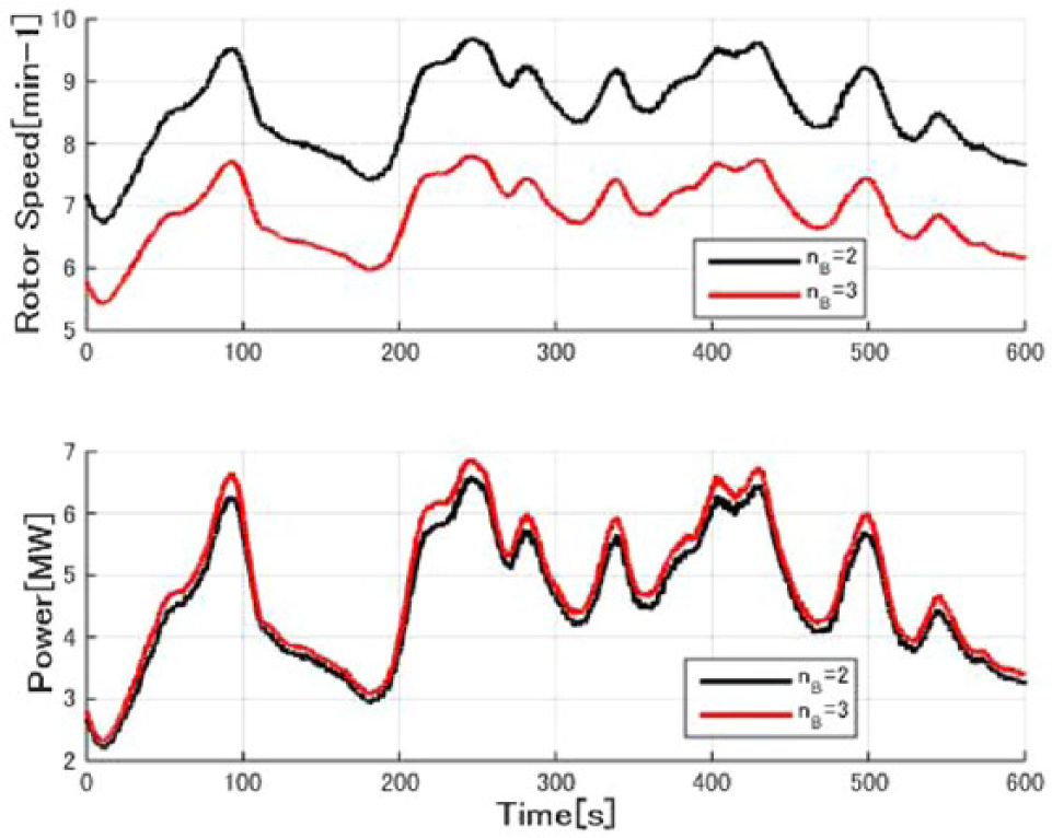
Time history of the rotor speed and power.
Blade deformations
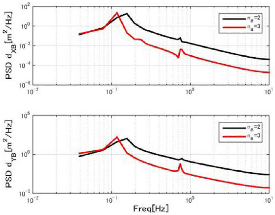
The power spectral densities (PSDs) of the blade tip deflections in the out-of-plane (dXB) and in-plane (dYB) directions are shown in Figure 5, and “nB” indicates the number of blades. The elements of the rotor speed (1P; 0.11–0.14 Hz) were shown to be outstanding in both deflections. The next element of rotor speed is approximately 0.74 Hz for the in-plane first mode (rotor second mode). However, the magnitude of the latter is approximately 2 orders lower than that of 1P. The elements of the eigen-frequency are not seen in the out-of-plane deflection due to the high aerodynamic damping of the blade.
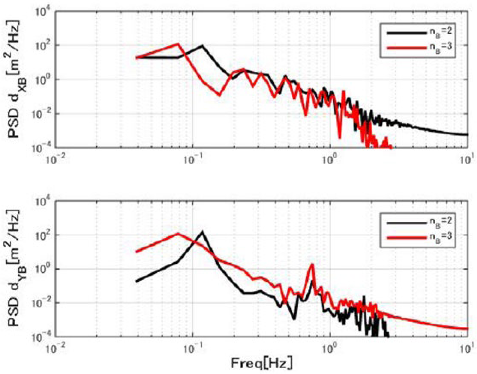
PSD of the blade tip deflection.
Rotor in-plane loads
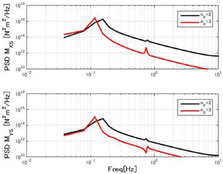
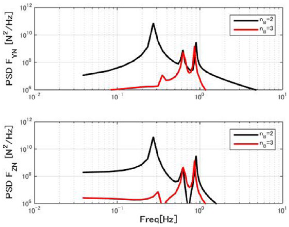
The time histories and PSDs of the rotor in-plane loads are shown in Figures 6 and 7. The elements of 0.28 and 0.33 Hz are the blade passing frequencies of the two- and three-bladed rotors, respectively. Those of the two-bladed rotors were 10 times larger than those of the three-bladed rotors, but no peak was found at 0.74 Hz, the edgewise first mode eigen-frequency.

Time history of the rotor load.
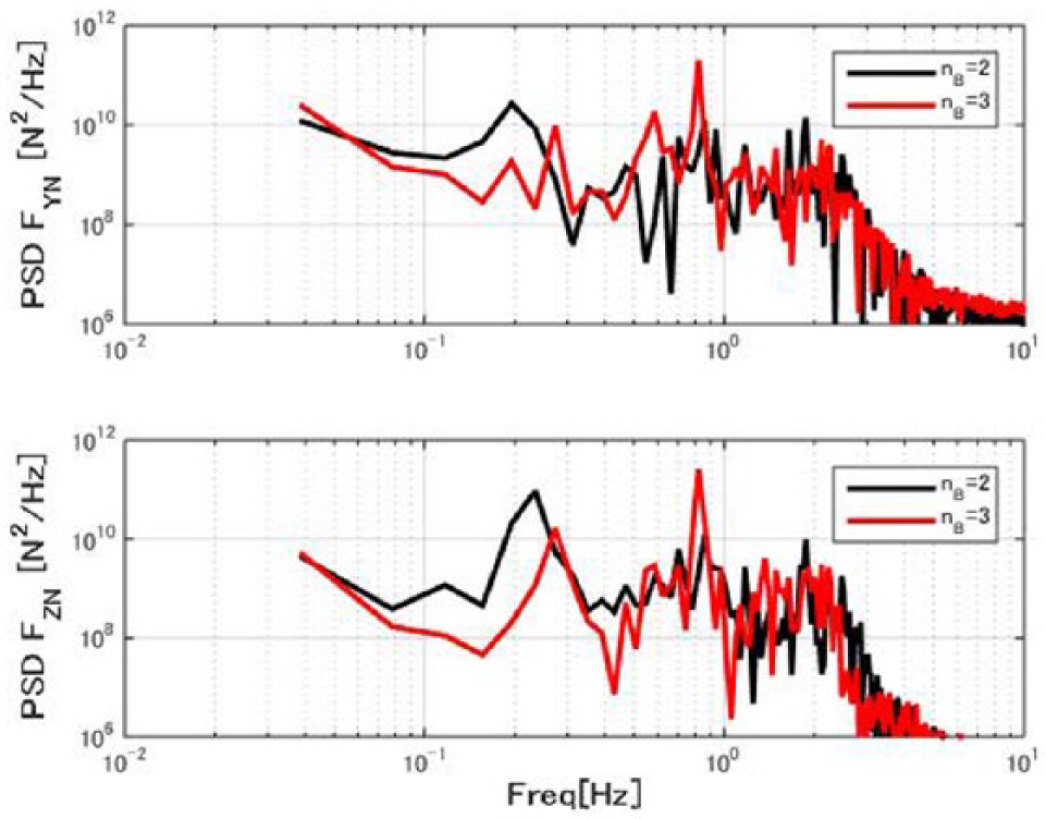
PSD of the rotor lateral and vertical load.
In both cases, the load fluctuations of the two-bladed rotor were much larger than those of the three-bladed rotor. These phenomena will be discussed in the successive sections.
Simple model aero-elastic simulations
The large vibrations shown in the previous section are essential to realizing large-scale two-bladed wind turbines. The simplified elastic model was formulated to make the mechanism clear.
Simulation conditions
Although most parts of the models assumed here are the same as in the previous section, several points were modified for this study. The towers were assumed rigid, and the rotors were elastic up to the second-order mode and each first order in the in-plane and out-of-plane directions. Here, the structural damping factors were assumed to be zero for simplification. Furthermore, the aerodynamic and mass imbalances were neglected.
To investigate the effect of gravity, 0 m/s2 gravity acceleration was assumed, as well as 9.81 m/s2. The simulation duration and sampling time were 60 and 0.05 s, respectively.
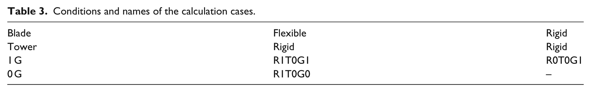
The cases calculated for two- and three-bladed turbines are shown in Table 3. The present research is focused on the blade in-plane self-excitation caused by gravity. The towers are assumed stiff because they do not affect the vibration much compared to the present phenomenon. A uniform steady flow of 8 m/s was assumed.
Conditions and names of the calculation cases.
Blade deformation
The PSDs of the blade tip deformations are shown in Figure 8. The elements at 1.4 and 7.4 Hz are excitations corresponding to the rotor speeds and the blade edgewise eigen-frequency. The latter are 3–4 orders lower than that of the former.
PSD of the blade tip deflections.
The PSDs of the blade edgewise bending are shown in Figure 9, which shows similar results to the tip deformations above. The PSDs of the blade loads of the two- and three-bladed rotors with elastic models are almost identical. There is no obvious difference in the comparison of the blade loads.
PSD of the blade root bending moment.
Rotor in-plane loads
Effects of the number of blades
The time histories and PSDs of the rotor in-plane loads are shown in Figures 10 and 11. The heavier rotor shifts the average values of the vertical load of the three-bladed rotor.
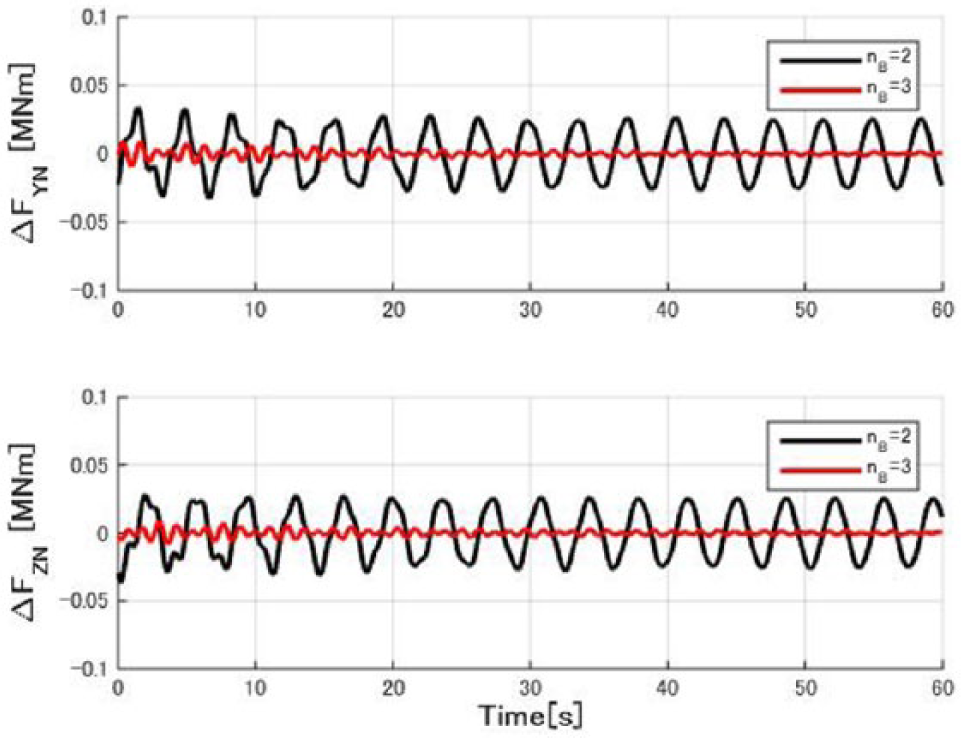
Time history of the rotor load to the average.
PSD of the rotor load.
The lateral and vertical loads show similar characteristics. The most obvious difference is found in the components of the blade passing frequencies. The 0.28-Hz element, 2P of the two-bladed rotor, is 3 orders higher than that of 0.43 Hz, 3P of the three-bladed rotor. Although the results are similar to those in the previous section, it is more obvious because turbulence factors, such as wind turbulence and rotor imbalances, are neglected here. The 0.6-Hz components, which are shown in both cases, are caused by the blade edgewise eigen-frequency and the rotation. The 0.9-Hz components, which correspond to the 6P of the rotor speed, are also common in both cases, but the harmonics are soon damped, as shown in the time history in Figure 10. Although blade loads of the two- and three-bladed rotors are almost identical, the rotor in-plane loads of the two-bladed rotor are much higher than those of the three-bladed rotor.
Effects of the blade deformation and gravity
The effects of blade deformation and gravity were investigated in the two-bladed rotor. The time histories of the rotor in-plane loads of the two-bladed rotor are shown in Figure 12, both with and without gravity and blade elasticity. Large vibrations are seen in the case of “R1T0G1” in which elastic blades with gravity acceleration are considered, whereas “R0T0G1” and “R0T0G0” are almost zero. The PSD of “R1T0G1” is identical to “nB = 2” in Figure 11.
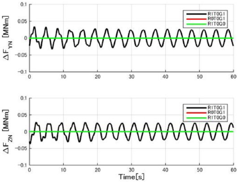
Time history of the rotor load to the average of the two-bladed rotor.
Effects of the rotor speed
The effects of the rotor speed were investigated for the two-bladed rotor. The PSDs of the rotor in-plane loads are shown in Figure 13. The generator torque demand was applied proportional to KOpt (N m s2/rad2) and the square of the generator speed. The 0.22- to 0.33-Hz elements in the PSD are the blade passing frequencies, which tend to decrease as KOpt increases. The 0.6- and 0.9-Hz components, generated by the edgewise eigen-frequency and the rotation, are 2 orders lower than the rotor speed, and they do not depend on the rotor speed.

PSD of the rotor load.
Spring–mass model
To develop the mechanism of the self-excitation of the rotor models in the previous section clear, the rotor model was expressed with simplified masses and springs.
Blade in-plane deviation
The blade vibration models defined here are shown in Figure 14. In the blade axis, XB and ZB are parallel to the rotor axis and blade axis, and XB-YB-ZB consists of a right-handed coordinate system.
Blade deviation in the blade coordinate system.
The coning angle, the angle between the blade axis and rotor plane, and the tilt angle, the angle between the rotor axis and horizontal lines, were neglected because they do not affect the characteristics of the models when the aerodynamic terms are neglected.
Both inboard R − r and outboard r are rigid bodies connected with a rotational spring kφ. Therefore, there is the following relation to the corresponding modal mass m and eigen-frequency ωφ

The neutral point azimuth angle of the nth blade Φ n of an nB-bladed rotor is as below
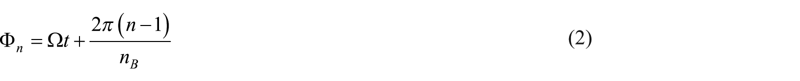
where Ω and t are the rotor angular speed and time, respectively. The rotor azimuth angle is defined as identical to that of the first blade.
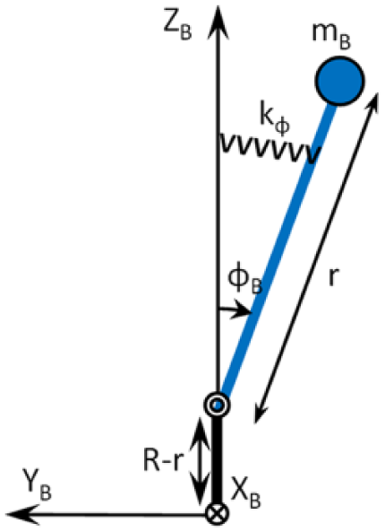
Blade in-plane deviation, expressed in the nacelle coordinate system, is shown in Figure 15, where ZN is upward, XN is parallel to the XB-axis, and XN-YN-ZN consists of a right-handed coordinate system. The in-plane position of the mass center of the nth blade in the nacelle coordinate system is as follows
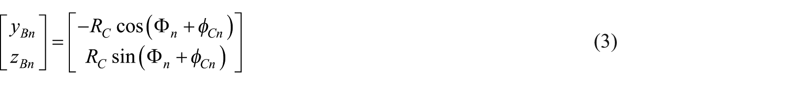
where


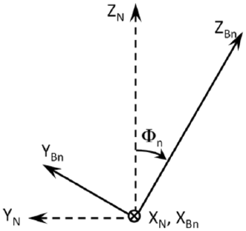
Blade (Bn) and nacelle (N) coordinate systems.
By neglecting the terms of φn over the second order, the Lagrangian of the nth blade is as follows

where g indicates gravity acceleration. The first through third terms on the right-handed side are the kinematic, elastic, and potential energies, respectively.
Furthermore, by neglecting the second orders of φn, the rotor in-plane load of nth blade is as follows

where

The left- and right-hand sides show the Mathieu equation and sinusoidal excitation, respectively.
Blade in-plane loads
The in-plane bending moments of the nth blade are as follows

where the first and second terms of these equations indicate the moments of spring reaction and gravity acceleration.
The rotor in-plane loads in the blade coordinate system are shown as follows
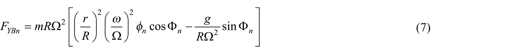
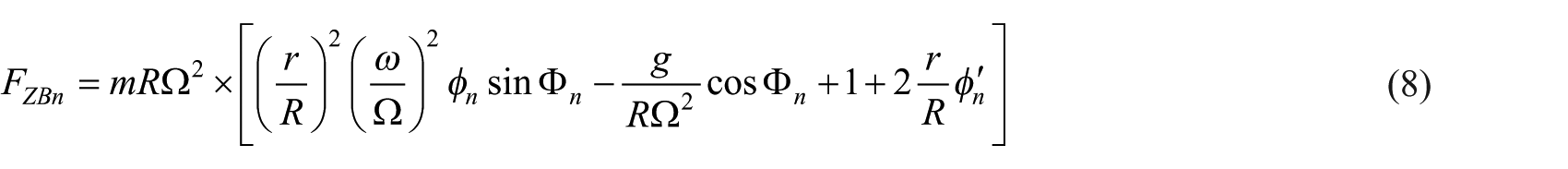
By converting the values into the nacelle coordinate system, the blade lateral and vertical loads are shown as follows
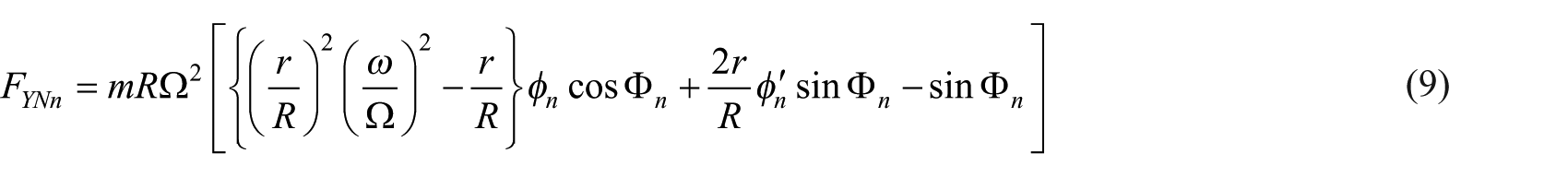
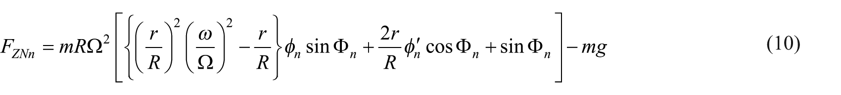
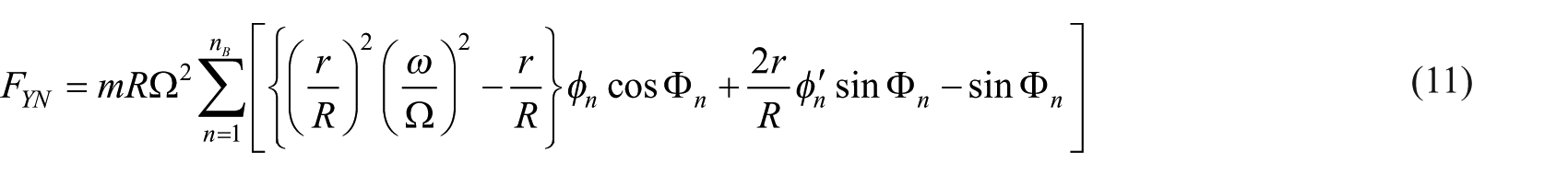
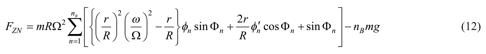
Rotor in-plane loads
The rotor lateral and vertical loads are introduced by summing equations (7) through (10) for nB blades
Approximation of blade deviation
In this section, approximated functions of FYN and FZN are derived around δ = ν2, assuming |ε| < 1. Here, ν is an appropriate integer.
First, δ and φn are expressed as polynomials of ε as below


By introducing these results into equation (5), the following equations are derived from the comparison of coefficients of ε0 and ε1


where

By introducing equation (17) as the boundary condition of equation (15), equations (18) and (19) are derived


In the same manner, equations (21) and (22) are derived from equations (20) and (16)


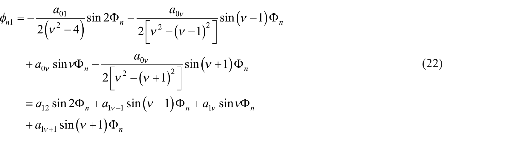
where

The approximated blade loads are derived as below from equations (7) through (10) and (24)


Blade model
The approximated equations derived in the previous section were applied to the model described in section “Outlines of aero-elastic simulations.”
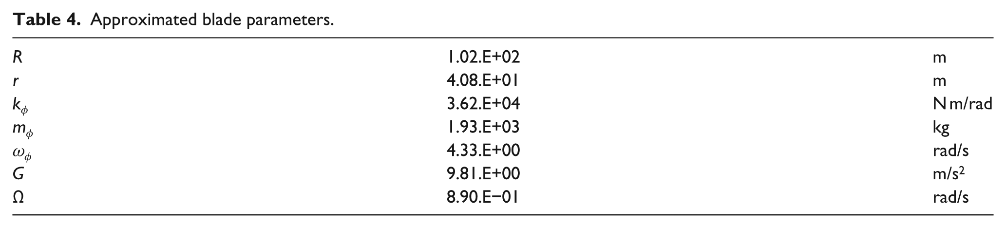
To apply the bladed model in section “Outlines of aero-elastic simulations” to the model in section “Aero-elastic simulation results,” the edgewise mode shape was simplified. The model shape was expressed by a linear function in the range of 20%–100% of tip deviation, which is shown in Figure 16 as the broken line. The parameters calculated by the blade model are shown in Table 4. ν = 5 is appropriate for this model, and |ε|~0.2 < 1 was shown to be consistent with the conditions of the approximation in the previous section.
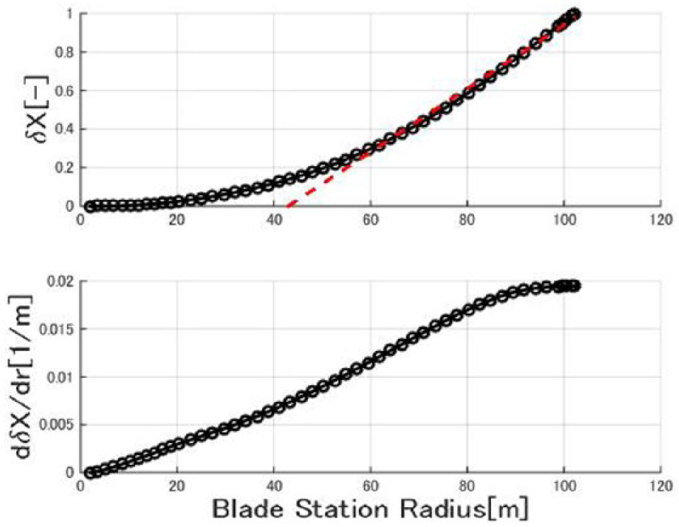
Blade in-plane first mode shape.
Approximated blade parameters.
Rotor load approximation
Equations (26) and (27), approximations of the rotor in-plane loads of an nB-bladed rotor, are calculated by equations (23) and (24).

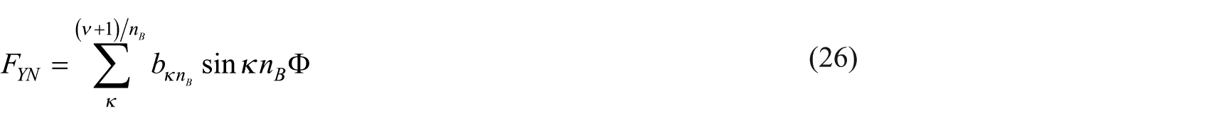

where
and
Blade deformation and loads
The blade deformation coefficients a are shown in the top subplot of Figure 17. The rotor speed of the 1P element of ε0 and 5P, which corresponds with in-plane eigen-frequency, has large values. Although the coefficients of the higher order of ε are available following similar procedures, they decrease drastically. Therefore, terms higher than ε1 were neglected.
Coefficients for the deviation and the rotor in-plane loads.
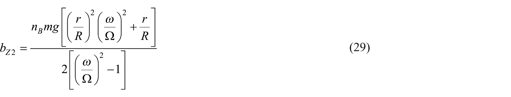
The coefficients of the rotor load approximation b are shown in the bottom subplot of Figure 17. The blade passing frequency 2P is outstanding for a two-bladed rotor, but the 3P component of the three-bladed rotor is somewhat lower. In both configurations, 6P components, which are affected by the in-plane eigen-frequencies, have larger values.
The in-plane deformations to the rotor azimuth angle are shown in Figure 18. The phase differences of the blades are 180° in two-bladed rotor and 120° in three-bladed rotor. The positions of the mass center are shown in Figure 19.
Time history of the tip angular deviation of each blade.
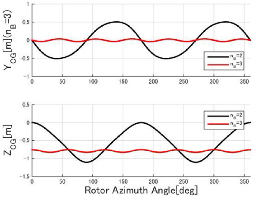
Time history of the horizontal and vertical motions of the center of the gravities of the rotor.
In the three-bladed rotor, the height of the mass center is always below the rotor center. Furthermore, the fluctuation is small because the three blades cancel the fluctuations with each other.
In the two-bladed rotor, the azimuth angles at the 0° or 180° blades are located on the top or the bottom of the rotor. In these positions, the height of the mass center is almost equal to that of the rotor center, and the rotor in-plane deformation does not affect the position of the mass center. With azimuth angles at 90° or 270° (where the blades are at the lateral positions), the mass center moves downward as blades droop. The motion of the mass center provides large vertical load fluctuation at 2P frequency. The lateral motion of the mass center is also large and periodic because the motion of mass center moves every half of the rotation.
Rotor in-plane load
The in-plane loads of both rotors are shown in Figures 20 and 21. In the case of two-bladed rotor, the load is doubled because the loads of both the blades affect the same phase. The phases of the loads correspond with those of the deformation. Large loads occurred when the rotor position shifted between the lateral and vertical positions.
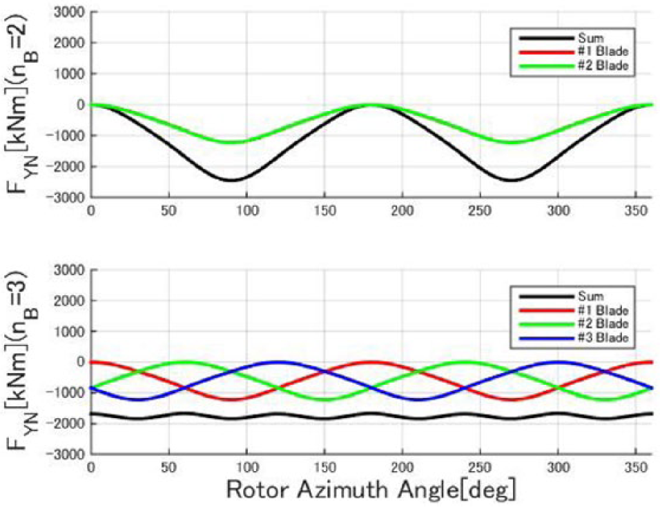
Time history of the rotor lateral loads of the two- and three-bladed rotors.
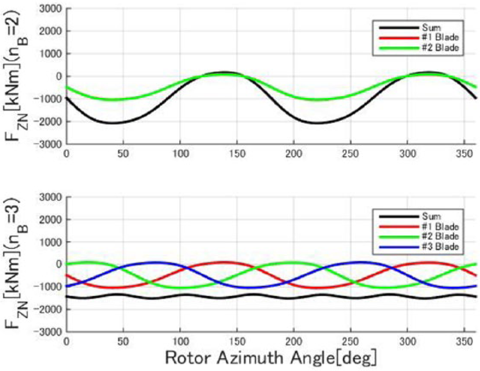
Time history of the rotor vertical loads of the two- and three-bladed rotors.
In the case of a three-bladed rotor, each blade deforms similar to the two-bladed rotor, but the three blades cancel the load fluctuations with each other. Therefore, the load fluctuation is small.
Discussion
Significant characteristics of rotor in-plane excitation appearing in aero-elastic simulations are modeled in the present simplified model, as shown in the previous sections. The perspectives of the two-bladed rotor for large-sized turbines were discussed based on the model.
Blade deformation and load reduction
The 1P element, which is outstanding for the in-plane deformation, is strongly affected by the term of a01.
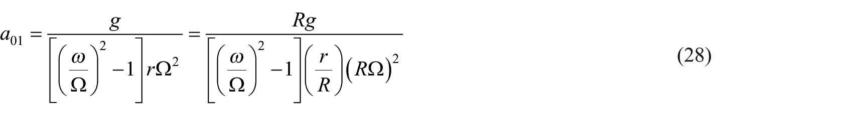
As wind turbines become larger, blade deformation and load fluctuation are increased. The following countermeasures are useful for reducing the term of the blade in-plane loads.
(1) Increase tip speed, RΩ: Adverse effects on noise and leading edge erosion are expected. The more slender the blades become at higher tip speed, the more difficult it becomes to maintain the stiffness. Furthermore, the tower should be stiffer to increase the eigen-frequency.
(2) Increase the eigen-frequency to rotor speed ratio, ω/Ω: Lighter and softer blades are necessary.
Rotor in-plane load reduction
The 1P element is predominant for rotor in-plane loads and is heavily dependent on the term below
Both mass reduction and increasing stiffness of the inboard section are effective in reducing the modal mass.
Conclusion
The effects of blade deformation, which is more evident in larger wind turbines, were studied through aero-elastic simulation using simplified models of both rotors of 10-MW wind turbines with a 204 m of rotor diameter.
Due to blade deformation, gravity acceleration, and rotor rotation, the blade significantly deforms the rotor in-plane. There are no significant differences in two- and three-bladed rotors.
The rotor mass center of the two-bladed rotor moves in-plane but that of the three-bladed rotor does not. These differences affect the rotor in-plane excitation.
The excitation is expected to increase as the size of the wind turbine increases. Hence, a two-bladed rotor is more challenging in large-scale wind turbines.
Footnotes
Declaration of conflicting interests
The author(s) declared no potential conflicts of interest with respect to the research, authorship, and/or publication of this article.
Funding
The author(s) disclosed receipt of the following financial support for the research, authorship, and/or publication of this article: This study was conducted with funding from the Research on Over 10-MW Class Wind Turbine Project of New Energy and Industrial Technologies Development Organization (NEDO) in 2013–2014 by contract with Hitachi, Ltd.