Abstract
Wind turbine towers (WTT), as tall slender structures, are exposed to complex loading conditions that may cause excessive oscillations affecting structural fatigue life and cost of maintenance; in this regard, vortex-induced vibration (VIV) is a challenging phenomenon to mathematically formulate and attenuating its resulting response in structures through added structural damping requires certain measures especially during assembly. Passive structural control devices have proven to be an effective solution in reducing structural vibrations and certain attributes of novel devices proposed in the literature could be exploited in new applications in a manner to overcome the limitations imposed by traditional dampers. In this paper, the effect of a magnetic damper with nonlinear stiffness and eddy current damping on VIV in off-shore WTT at four stages of installation is numerically investigated. Maximum VIV response of the tower is formulated using a spectral model for the off-shore DTU 10 MW reference wind turbine (RWT), taking into account the feasibility of implementing the device in terms of required space. The study reveals that the nonlinear damping device, in a compact and portable configuration, is capable of mitigating relative maximum normalized displacement and harmonic response due to VIV in off-shore WTTs at different installation stages. Based on the obtained results, the damper may be used as an installation aiding device to help facilitate tower erection and turbine assembly.
Keywords
Introduction
As wind turbines grow in capacity and size, taller towers are required to provide the desired swept area, posing limitations and associated challenges in tower design. The design approach is typically toward light-weight, slender towers, prone to combinations of environmental loads. Wind turbines are required to withstand severe environmental conditions, primarily originating in wind flow. Occasionally, wind action on cylindrical towers produces complications, excluding wind-induced drag force which causes along wind response of the structure. These complications may also be present while erecting the tower or assembling nacelle and rotor, temporarily hindering installation which result in added cost of wind farm construction.
When a bluff body is situated in a fluid flow, VIV may occur due to fluctuating fluid pressure resulting from the vortices alternately shedding on either side of the body. The regular pattern of these vortices is referred as von Karman vortex street. The fluctuating lift force, as a harmonically varying lateral load with a frequency equal to shedding frequency, will cause a cross-flow structural motion and becomes critical as the frequency approaches one of the fundamental natural frequencies of the structure, leading to resonant vibration, known as lock-in. VIV transfers a substantial amount of energy to a structure and the resultant fatigue is detrimental to structural lifetime (Sun et al., 2016). VIV of circular cylinders have been studied by many researchers (Bearman, 2011; Williamson and Govardhan, 2004) and it’s essential to be taken into account for slender structures such as chimney stacks and high risers. 1-DOF VIV of a single cylinder was investigated by Govardhan and Williamson (2000), focusing on frequency responses and formation of vortices and how they’re closely related to mass-damping parameter. Jauvtis and Williamson (2003) studied 2-DOF elastically mounted cylinder with low mass and damping, free to move in both across wind and along wind directions; they found that along wind DOF has negligible effect on across wind response of the cylinder in VIV which validated relevancy of previous works considering only across wind motion of the cylinders in VIV investigations; the authors categorized the vibration response into three initial, upper and lower branches. In a later study the same authors found a new so called “super-upper” branch in case of a reduced mass ratio (Jauvtis and Williamson, 2004). Single 1-DOF cylinder at low Reynolds number with different initial conditions was numerically investigated by Navrose and Mittal (2017); It was observed that in the middle of lock-in regime, multiple response states existed in addition to primary and secondary hysteresis near the ends of the lock-in regime. Most VIV studies in the past considered non-tapered cylindrical sections which yield conservative results applying to tapered section towers. In a numerical study conducted by He et al. (2024), VIV of 1-DOF cylinders with variable cross sections and incoming flows was considered and a delay was observed in the location of the cross-flow amplitude extremes compared to non-tapered cylinders which was attributed to the influence of the structural shear rate and expanded the upper branch. Kaja et al. (2016) investigated three-dimensional (3D) VIV numerical simulation of tapered cylinder to identify the difference with non-tapered cylinder in terms of response to vortex shedding; it was discovered that the lock-in regime of tapered cylinder was wider than the uniform one. Vortex shedding characteristics of a fixed linearly tapered cylinder in 3D flow regime was studied employing a computational fluid dynamics (CFD) model by Tamimi et al. (2014); The model was able to capture key physical characteristics of vortex shedding for tapered cylinders.
VIV in wind turbines usually occur in turbine idling or locked mode since the shedding vortices form a coherent wake structure and disrupting the coherent structure prevents vortex lock-in (Manolas et al., 2022); thus, it is more likely to be problematic in turbine parked condition or during assembly and maintenance procedures. Ebstrup et al. (2024) conducted numerical investigation of VIV of a non-tapered WTT segment at high Reynolds number using Improved Delayed Detached Eddy Simulation turbulence model; they reported that the Strouhal number was greater than previously reported values in the literature. To assess aero-elastic instabilities of different wind turbine configurations during assembly, a semi-empirical framework was proposed by Manolas et al. (2022), where using the aero-elastic tool, VIV risk level of each configuration was examined. Viré et al. (2020) performed two-dimensional numerical study of WTT under VIV excitation; they revealed the dependency of aerodynamic damping on frequency ratio and how it could lead to self-limiting as well as self-exciting VIV of the tower when it’s left to vibrate freely. With the purpose of investigating the fundamental mechanisms that trigger and sustain VIV in WTT segments, a new methodology was developed by VimalKumar et al. (2024) that dissects different force components involved in the phenomenon; it was found that at trans-critical Reynolds number (Re > 3
Adding structural damping has proven to be an effective solution for reducing VIV (Li et al., 2018). Employing various types of damping devices in wind turbines was examined by many researchers so far (Kandasamy et al., 2016; Rahman et al., 2015; Zuo et al., 2020), among which passive control devices are favored the most since they can function without external source of energy and the need of complex algorithms; however, the simplicity of passive devices comes with limitations in performance. Tuned mass damper (TMD) is the simplest type of passive dampers which consist of a mass, spring and dashpot element; by tuning TMD’s natural frequency to one of the structure’s fundamental frequencies, it would dissipate the structure’s vibrational energy through dashpot element by resonating out of phase. Utilizing TMDs in WTTs was first investigated by Enevoldsen and Mørk (1996) where the optimal tower and TMD design in sensitivity analysis demonstrated acceptable performance of TMD equipped WTT. Murtagh et al. (2008) examined the performance of a TMD installed in wind turbine nacelle in reducing tower vibrations due to wind-induced forces. Stewart and Lackner (2013) employed two independent TMDs, one in fore-aft and the other in side-side direction to reduce vibrations of WTT with fixed bottom and floating type foundations in both directions. Pendulum damper was later proposed for bi-directional vibration mitigation (Jahangiri and Sun, 2020; Sun and Jahangiri, 2018) and it was found that the pendulum damper proposed could outperform dual TMDs formerly proposed (Stewart and Lackner, 2014; Tong et al., 2015; Zhao et al., 2018); however, given the fact that the pendulum cable length and its natural frequency are inversely proportional and considering low fundamental frequency of WTTs, the pendulum damper may face feasibility issue on account of limited space available in wind turbine nacelle. TMDs, despite their benefits, suffer from limitations like sensitivity to detuning, additional required mass and space for stroke where the latter causes difficulties in utilizing them in applications with space limitations such as wind turbines. Nonlinear dampers on the other hand, are believed to be able to alleviate some of the limitations imposed by linear dampers (Lu et al., 2018; Main and Jones, 2002; Pourjafar et al., 2025; Roberson, 1952). Tuned liquid column dampers (TLCDs) have also been proposed for WTT vibration control (Chen et al., 2025; Colwell and Basu, 2009; Hemmati et al., 2019; Zhang et al., 2025). However, because their natural frequency is primarily determined by geometric dimensions, their practicality is limited in wind turbines where nacelle space is constrained (Zuo et al., 2020). While structural damping devices target vibration suppression directly, an alternative approach lies in pitch control strategies that regulate aerodynamic loads to stabilize turbine performance. Advanced pitch control strategies, such as IMC-PID, hybrid PI-fuzzy logic, and STATCOM-coordinated type-2 fuzzy logic, have been shown to effectively smooth output power, regulate terminal voltage, and improve oscillatory stability of grid-connected wind turbines under wind speed variations and fault conditions (Naik and Gupta, 2016a; 2016b, 2018).
Magnetic dampers, considering the nonlinear nature of magnetic forces, are types of nonlinear (in terms of stiffness) damping devices. Magnetic vibration absorbers were first introduced by Kojima and Nagaya (1985) in a simple configuration consisting two fixed magnets applying repulsive forces to a moving magnet placed in between. Negative stiffness magnetic damper was examined by Shi and Zhu (2015) where corrective forces were applied to the moving magnet in two device configurations. Another magnets’ layout combining negative and positive stiffness provided by corrective and repulsive magnetic forces was proposed as tunable linear and nonlinear stiffness magnetic vibration absorber and its effectiveness on response mitigation of a three-storey structure was examined (Benacchio et al., 2016; Feudo et al., 2018). The effect of a bi-directional magnetic damper on reducing WTT first vibration mode response due to aerodynamic forces was compared to a TMD where the authors found that the magnetic damper can provide comparative results with less required space (Pourjafar et al., 2025). Following that study, Pourjafar and Razzaghi showed that under broadband excitations, nonlinear magnetic dampers can compete with linear TMDs with smaller damper to structure mass ratios (Pourjafar and Razzaghi, 2025). Further investigations demonstrated vibration control performance and robustness of the magnetic damper in wind turbine tower under seismic excitation (Pourjafar, 2026).
Although abundant studies regarding the use of damping devices in WTTs exist in the literature, research on WTT VIV suppression using dampers, specifically during installation is scarce. In this paper the performance of a magnetic damper, proposed by the authors in a previous study, in suppressing DTU 10 MW off-shore WTT across-wind response to VIV at four installation stages is investigated using a spectral model.
Off-shore tower
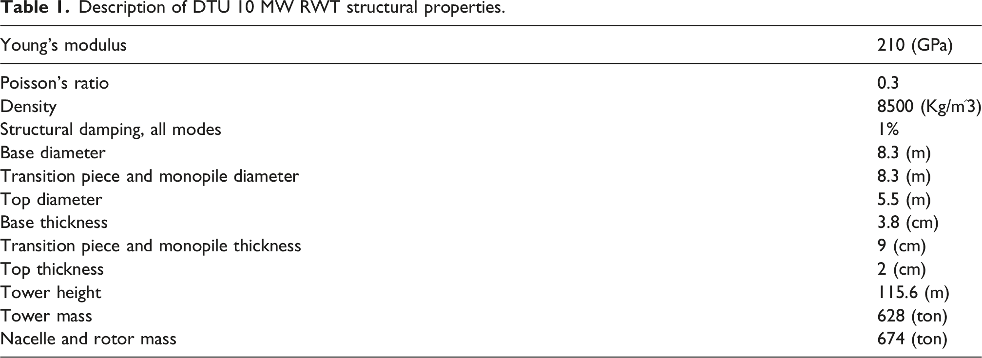
The schematics of the supporting structure of DTU 10 MW off-shore reference wind turbine (RWT) and the equivalent tower with the simplifications in the current study is illustrated in Figure 1 which is based on the previously published reports and investigations. The superstructure includes the main tower, a transition piece, and the monopile with 25m and 45m submerged in water and embedded in seabed, respectively. The rotor-nacelle assembly (RNA) is modeled as a lumped mass since VIV occurs mostly in wind turbine parked/idling conditions or during assembly or maintenance procedures (Manolas et al., 2022) and it’s a typical assumption in wind turbine tower VIV investigations (as in (Chen et al., 2023)). The monopile foundation is replaced with a stiffness matrix at seabed and the submerged monopile is modeled using added mass assumption for hydrodynamic pressure. Table 1 presents the specifications of the DTU 10 MW RWT based on DTU Wind Energy Report-I-0092 (Bak et al., 2013). In the following sections, the assumptions made in modeling the structure for the dynamic analysis will be explained briefly. Details of the simplified off-shore wind turbine tower. Description of DTU 10 MW RWT structural properties.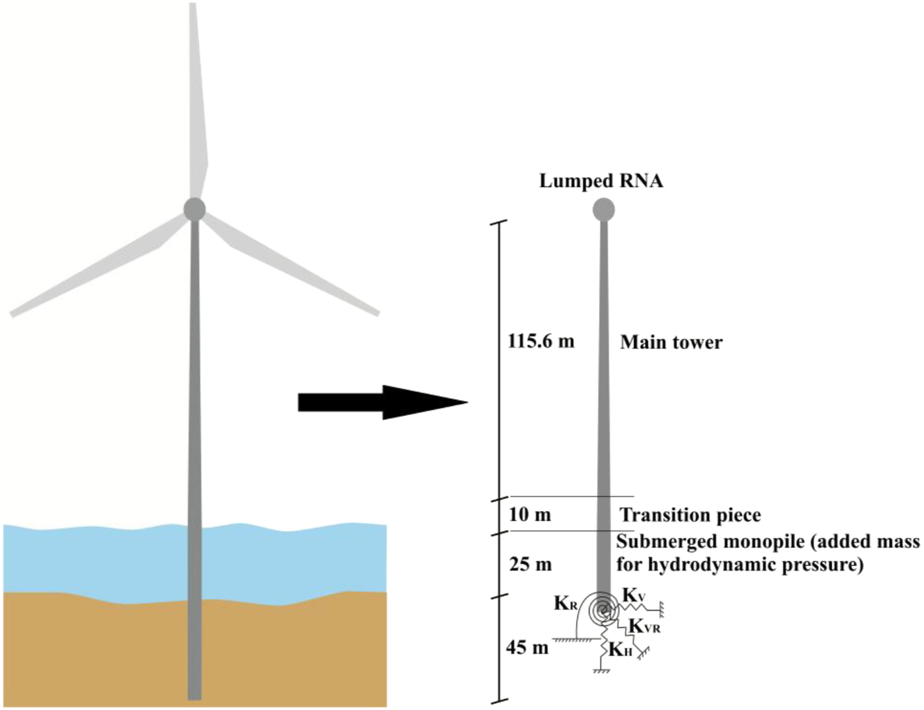
Added mass for hydrodynamic pressure
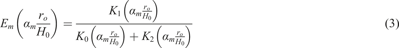
The supporting structure of DTU 10 MW RWT, as presented in Figure 1, is comprised of the main tower installed on top of the monopile substructure through the transition piece. The substructure is partially submerged in water and the water monopile interaction is modeled using the added mass due to hydrodynamic mass assumption (Goyal and Chopra, 1989; Jiang et al., 2017). The added mass of the submerged monopile in still water could be obtained as a function of distance above seabed (Goyal and Chopra, 1989) as,

Coupled elastic stiffness matrix for monopile foundation
In order to take into account the soil foundation interaction instead of fixed bottom monopile base boundary condition, an elastic stiffness matrix is introduced at seabed level of the structure so the base condition could be modeled more realistically. The stiffness matrix (Bergua et al., 2021, 2022) in equation (4), with coupled horizontal-rotational and uncoupled vertical-torsional elements, were used in BModes (Bir, 2006) to obtain the natural frequencies and mode shapes of the superstructure. BModes is a finite element code that provides coupled modes of WTTs and blades; it is capable of estimating eigenmodes of WTT’s with different boundary condition at tower base.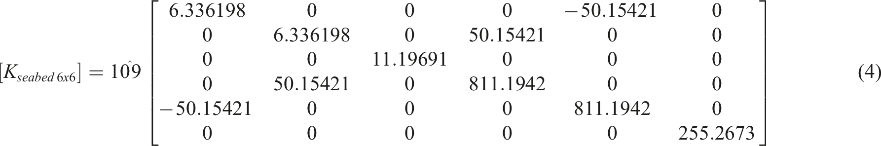
Mode shapes and natural frequencies of the full structure
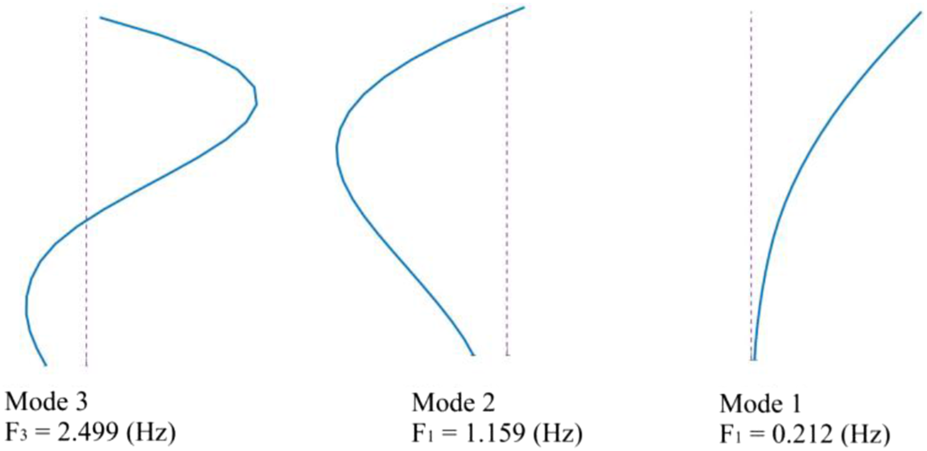
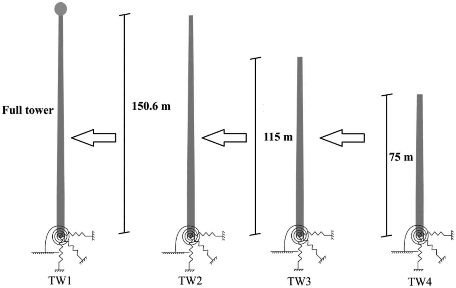
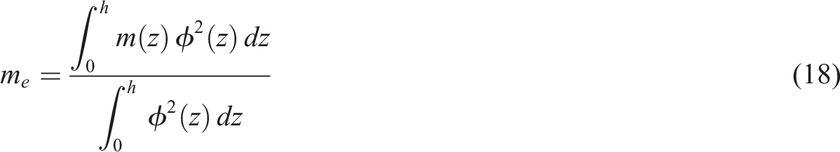
Following the assumptions made in previous subsections, the mode shapes and natural frequencies of the tower was obtained using BModes. The first three modes of the tower with tip mass are illustrated in Figure 2. It should be noted that the non-zero base displacement is attributed to flexibility of seabed and the resulting monopile-soil interaction which is taken into account in the finite element program. The procedure was repeated for three additional tower cases representing different installation stages, and the required modal analysis data were obtained for each case. Figure 3 illustrates all four installation stages considered in this study, including the final stage, which is also shown in Figure 1. The generalized displacement of the first three mode shapes and the magnetic damper together constitute a four degrees of freedom (DOF) system for the dynamic modal analysis with the dynamic equation of motion defined as: Mode shapes of the tower with tip mass. The investigated towers representing different installation stages.


Magnetic damper
The towers are equipped with a magnetic damper presented in Figures 4 and 5. Detailed description of the damping device may be found in (Pourjafar et al., 2025). The stiffness and damping force of the magnetic damper are defined as follows: Two-dimensional schematic presentation of the proposed magnetic damper [8]. Three-dimensional schematic view of the magnetic damper [8].

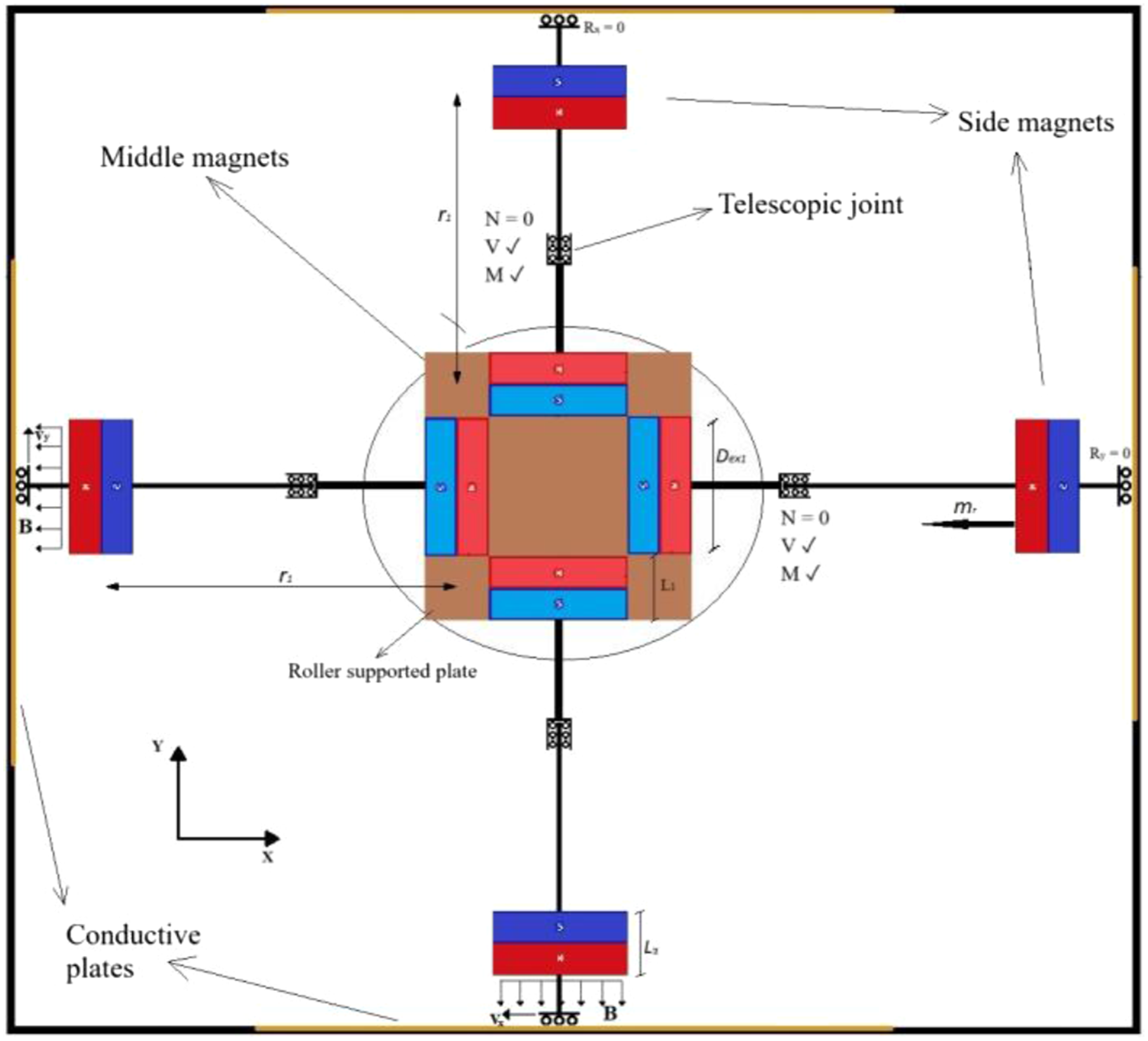
The damping device is optimized for magnets’ dimensions, type and initial distance between the magnets (r
1
) through exhaustive numerical grid search for damper parameters with the objective of minimizing the Root Mean Square (RMS) of the tower top displacement-time history for the case of full tower with tip mass (TW1), considering space availability inside the nacelle (or on top of the nacelle which is feasible given the flat configuration of the device). However, in order to address VIV issues in the installation phase, another damping device needs to be designed considering the available space in the smallest tower section (Figure 6) and given the compact and portable nature of the device, it could be an installation aid to reduce unwanted vibrations that might cause difficulties in establishing wind farms. The new, smaller device is optimized for the case of full tower with no tip mass (TW2) which has the smallest cross section at the top and its effectiveness on the prior erection phases, that is, TW3 and TW4 is investigated. Detailed properties of both damping devices and the towers are tabulated in Tables 2 and 3. TW2 (and TW1) top section minimum diameter versus maximum dimension of the damper box. Dampers properties. Dex, Din, and L denote magnets’ outer diameter, inner diameter, and thickness and Br is their residual flux density. *The damping ratio indicated in the table is defined as the ratio of the eddy current damping force to the critical damping of an equivalent linear TMD tuned to structure’s first natural frequency with 0.98 tuning ratio. Towers’ properties.
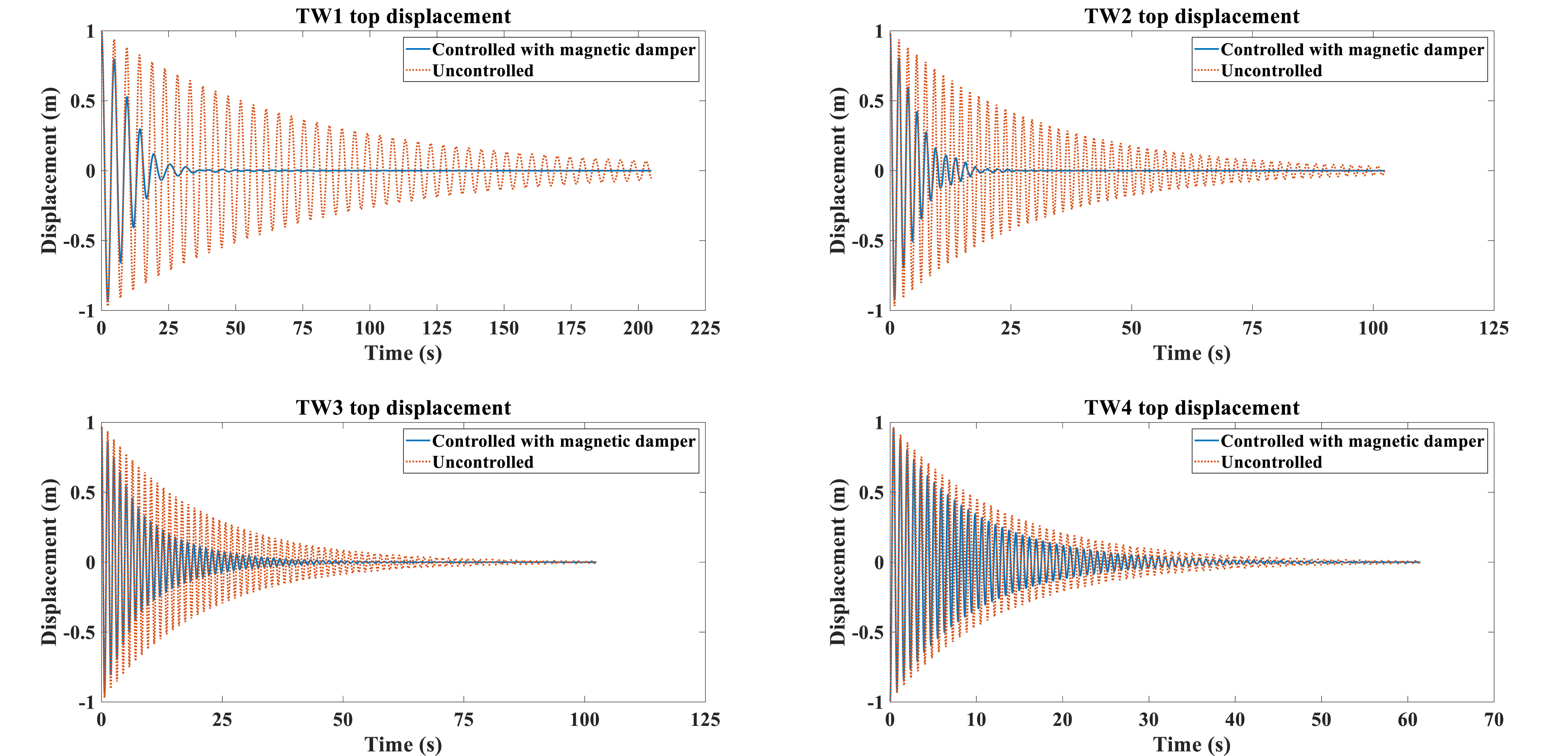
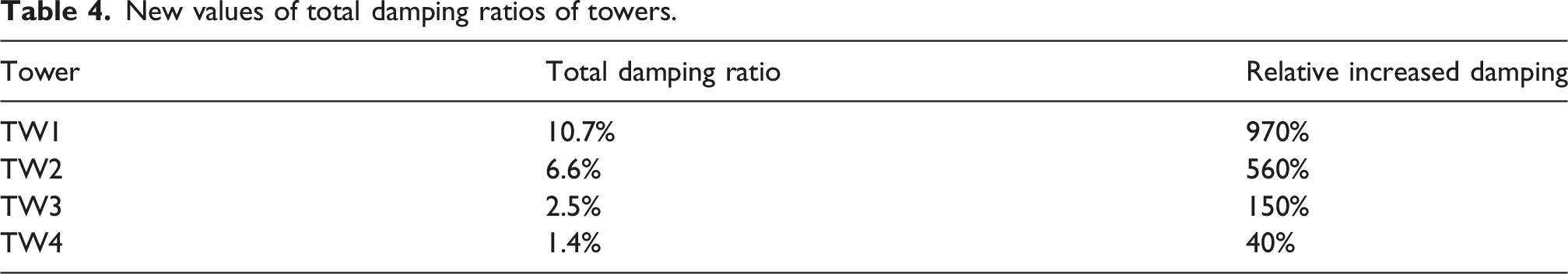
The free oscillation response to initial first generalized displacement corresponding to first eigenmode of the towers with and without structural control is demonstrated Figure 7. It is evident that the downsized damper, optimized for TW2, is also effective in increasing total damping of the other two towers (TW3 and TW4) which may imply that the nonlinear stiffness damper has a wide effective frequency band, since the first eigenfrequencies of these cases are noticeably higher compared to TW1; yet it should be noted that the damper to structure mass ratio is slightly increased considering that the parameters of the damper are kept the same for TW3 and TW4. In Table 4, the new values as well as the relative increment (compared to uncontrolled cases) of total structural damping ratios, obtained from logarithmic decrement method (equation (12)) applied to free vibration responses are reported. Top displacement of the towers due to mode 1 initial displacement free vibration with and without magnetic damper. New values of total damping ratios of towers.

Vortex induced vibrations
VIV investigation of the towers depicted in Figure 3 is conducted employing a spectral model based on the Vickery and Basu’s mathematical model (Vicker and Basu, 1983a, 1983b). The model represents the motion induced forces due to VIV by a nonlinear aerodynamic damping force, superimposed upon a narrow band random force representing the vortex shedding forces applied to a stationary cylinder. The model’s formulation for tapered towers is adopted from (Livanos, 2018).
The spectrum of the fluctuating lift force is defined as


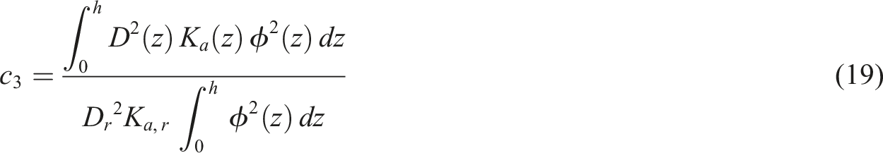
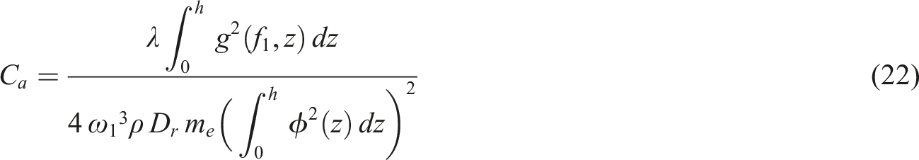
The generalized aerodynamic damping normalized by critical damping is expressed as
The standard deviation of the deflection of the tower top is obtained using the following equation,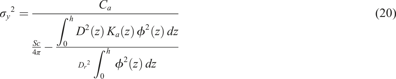


The values of 

The exclusive consideration of the first mode is justified by equation (25), especially for TW3 and TW4. For these cases, considering the second vibration mode would yield critical wind velocities of 159 m/s and 78 m/s, respectively, which are highly improbable.
Results and discussion
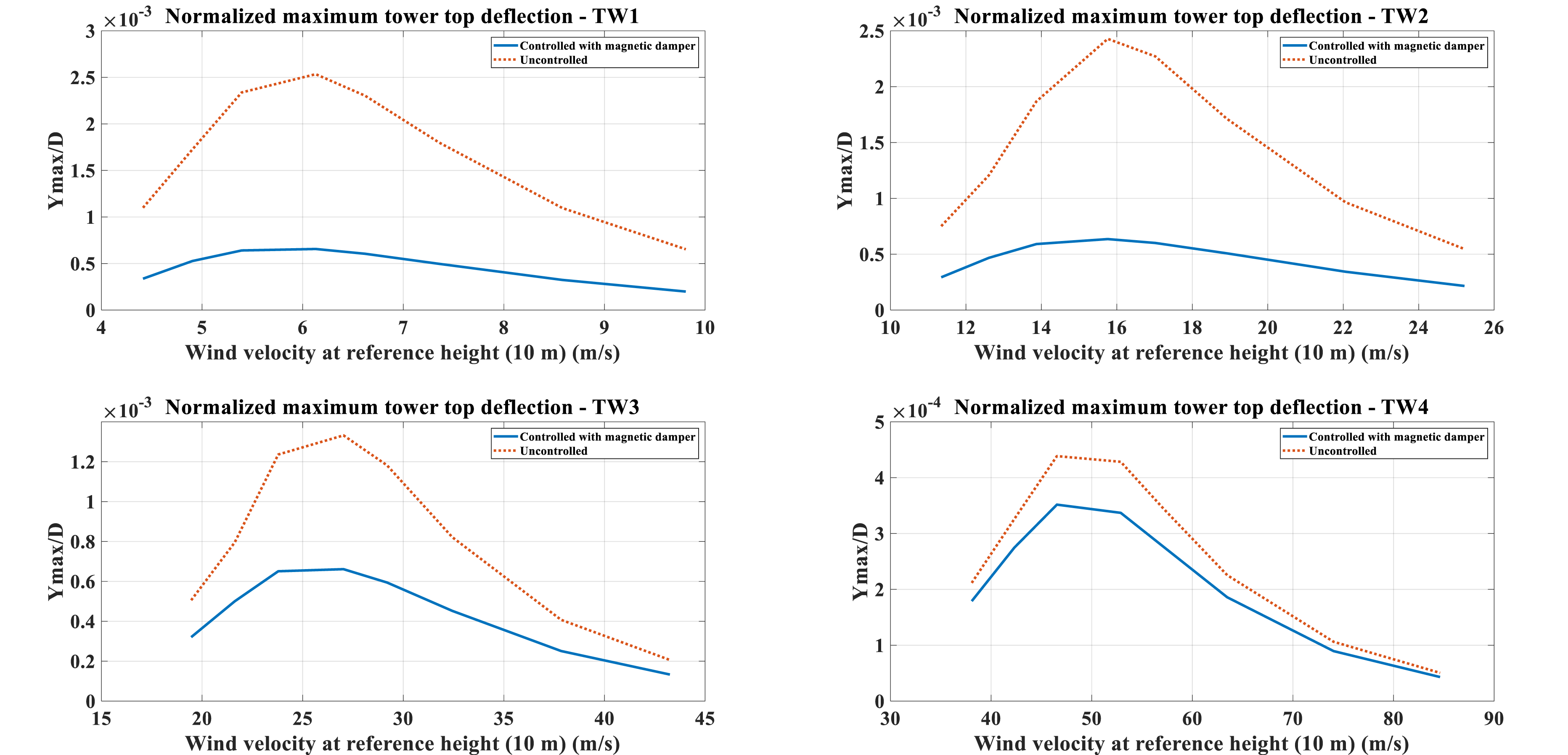
The Aerodynamic damping of the towers at different reference height wind velocities. Normalized maximum top deflection of the towers at different reference height wind velocities.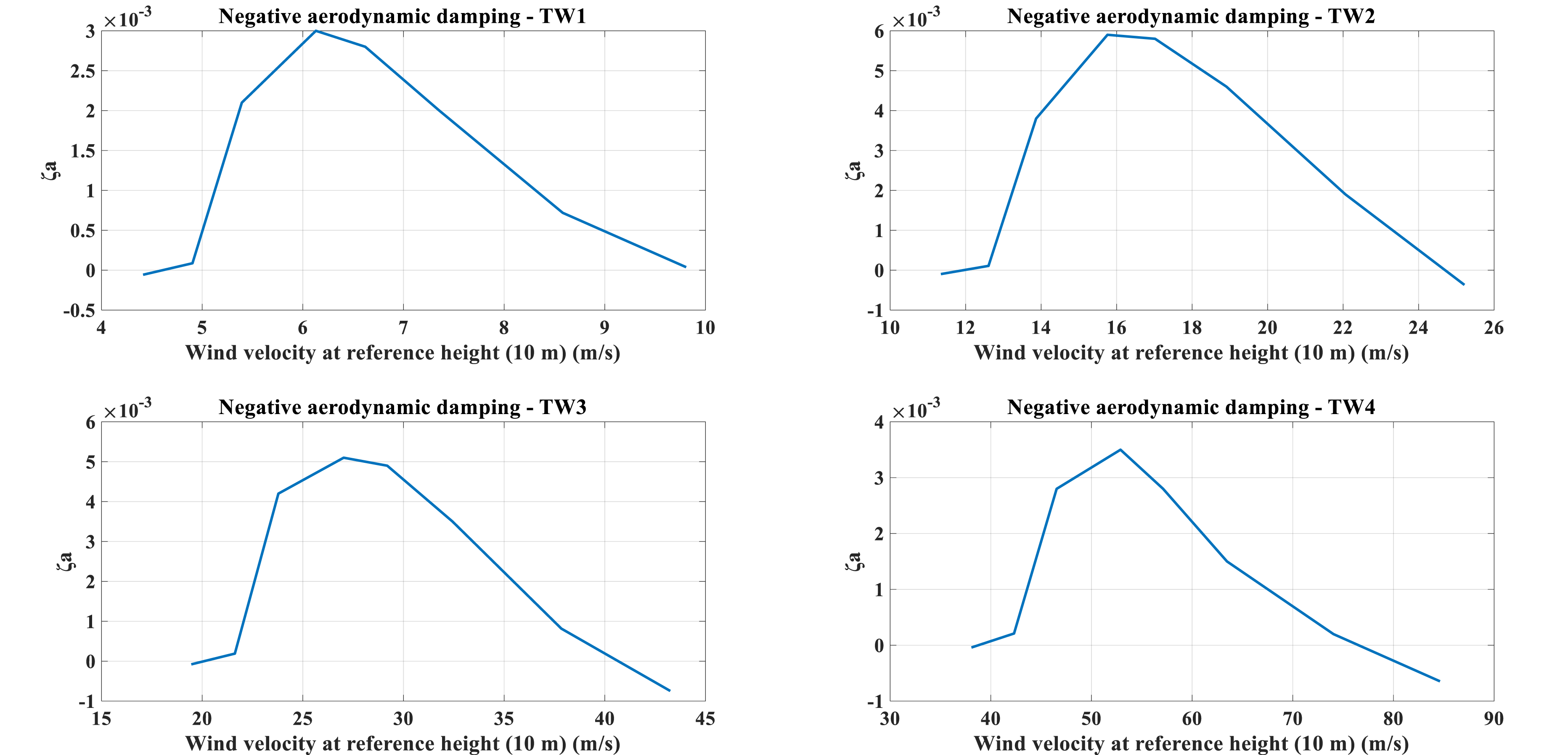
The turbulence intensity ( Normalized maximum top deflection of the towers at different turbulence intensity (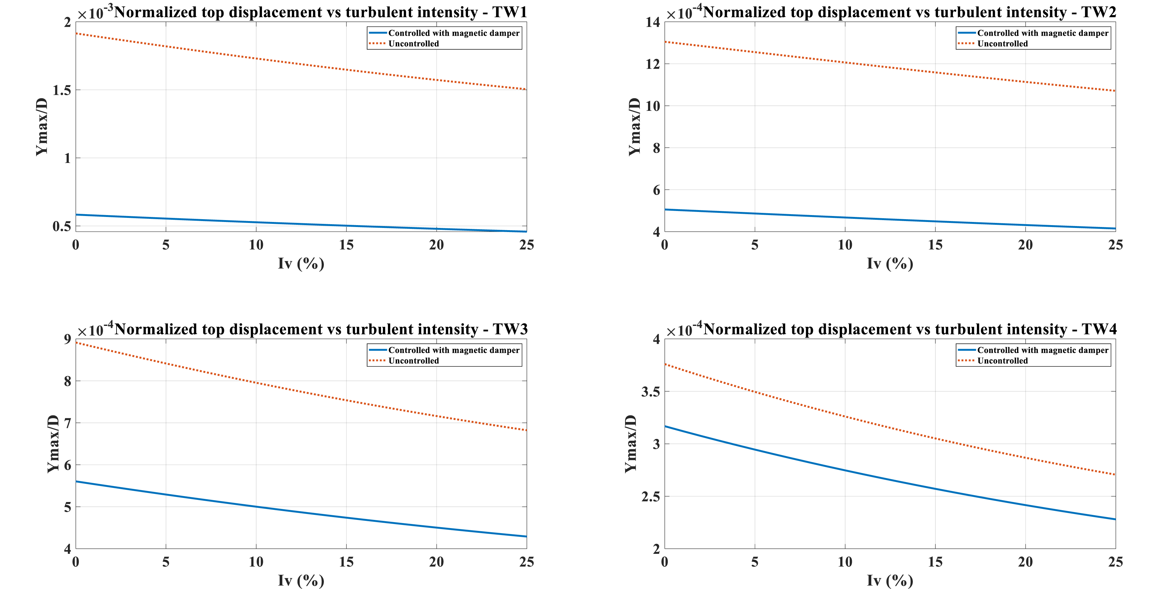


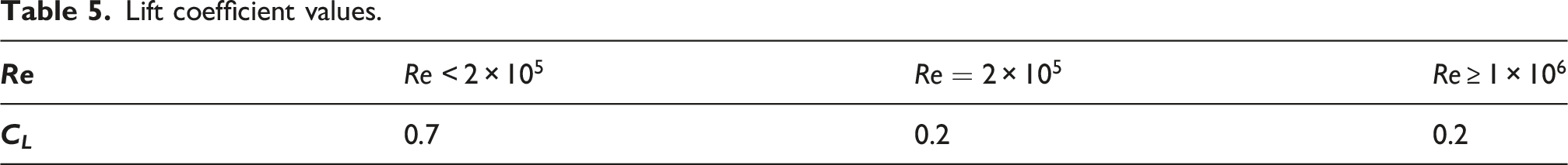
Lift coefficient values.
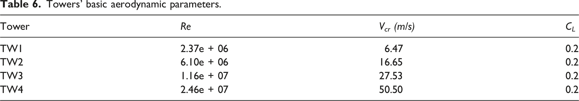
Towers’ basic aerodynamic parameters.
The time history-response of the towers subjected to the harmonic lift force in equation (26) are obtained by integrating the dynamic equations of motion (5) in time domain described in section 2.3 and substituting the following for the modal force,
The lift force is applied to the span of the tower where Wind shear versus critical wind velocity plot. The height refers to the height above transition piece.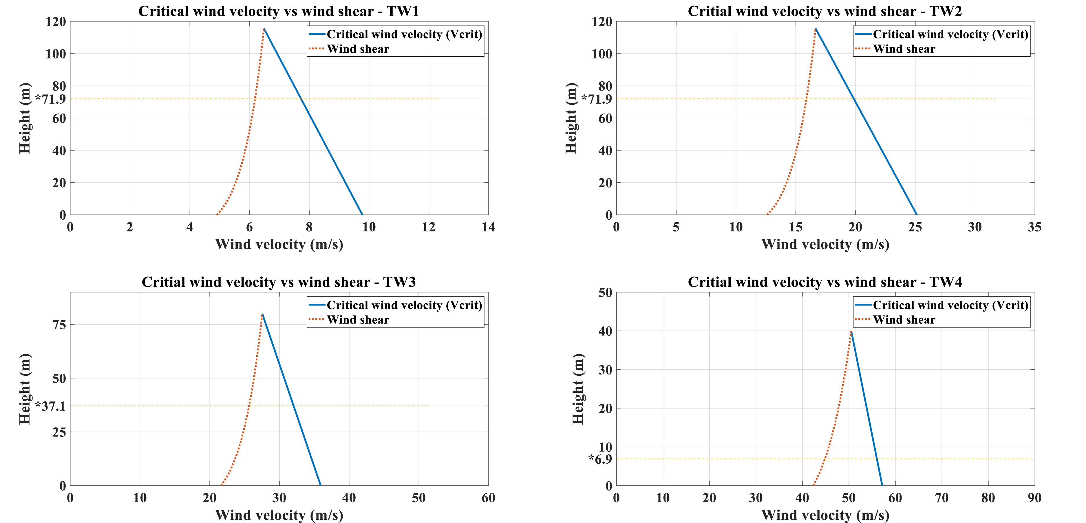
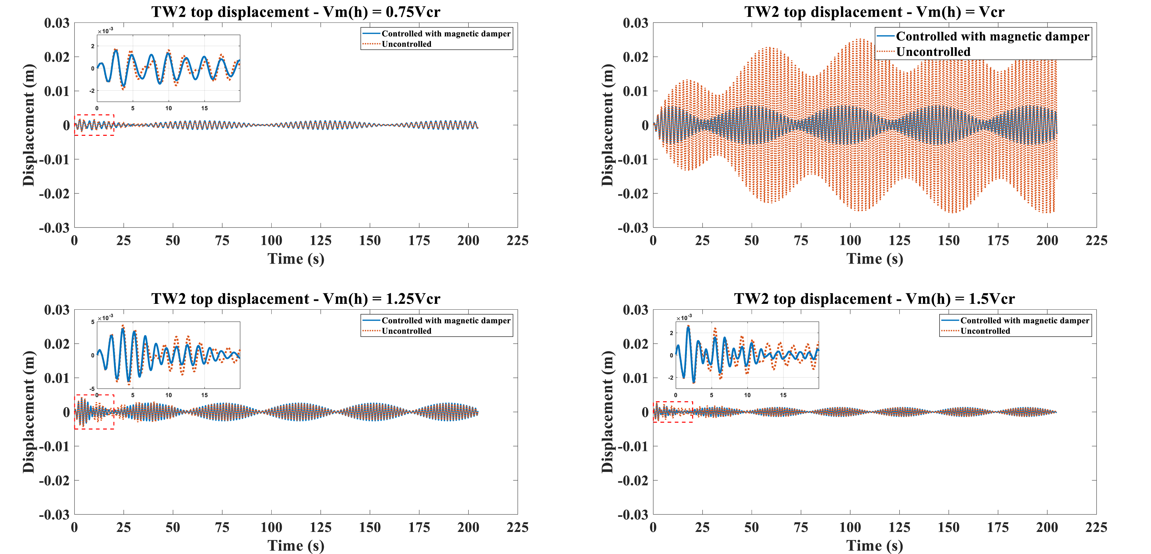
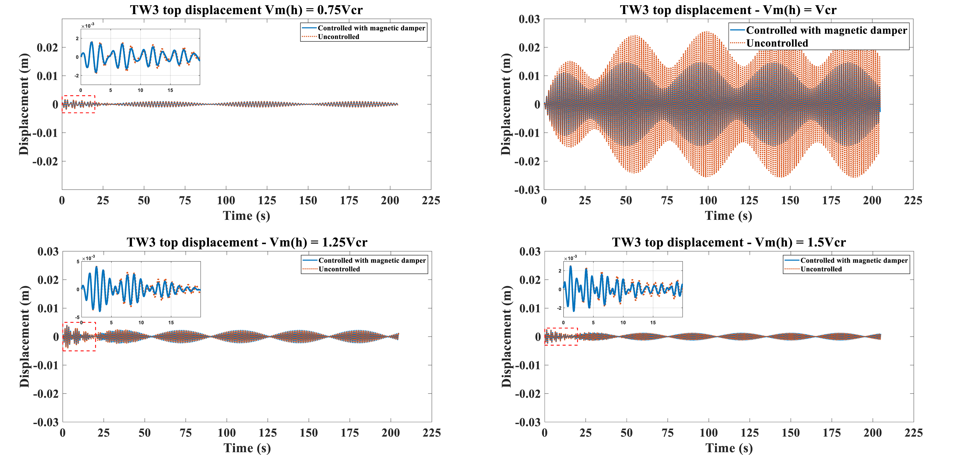
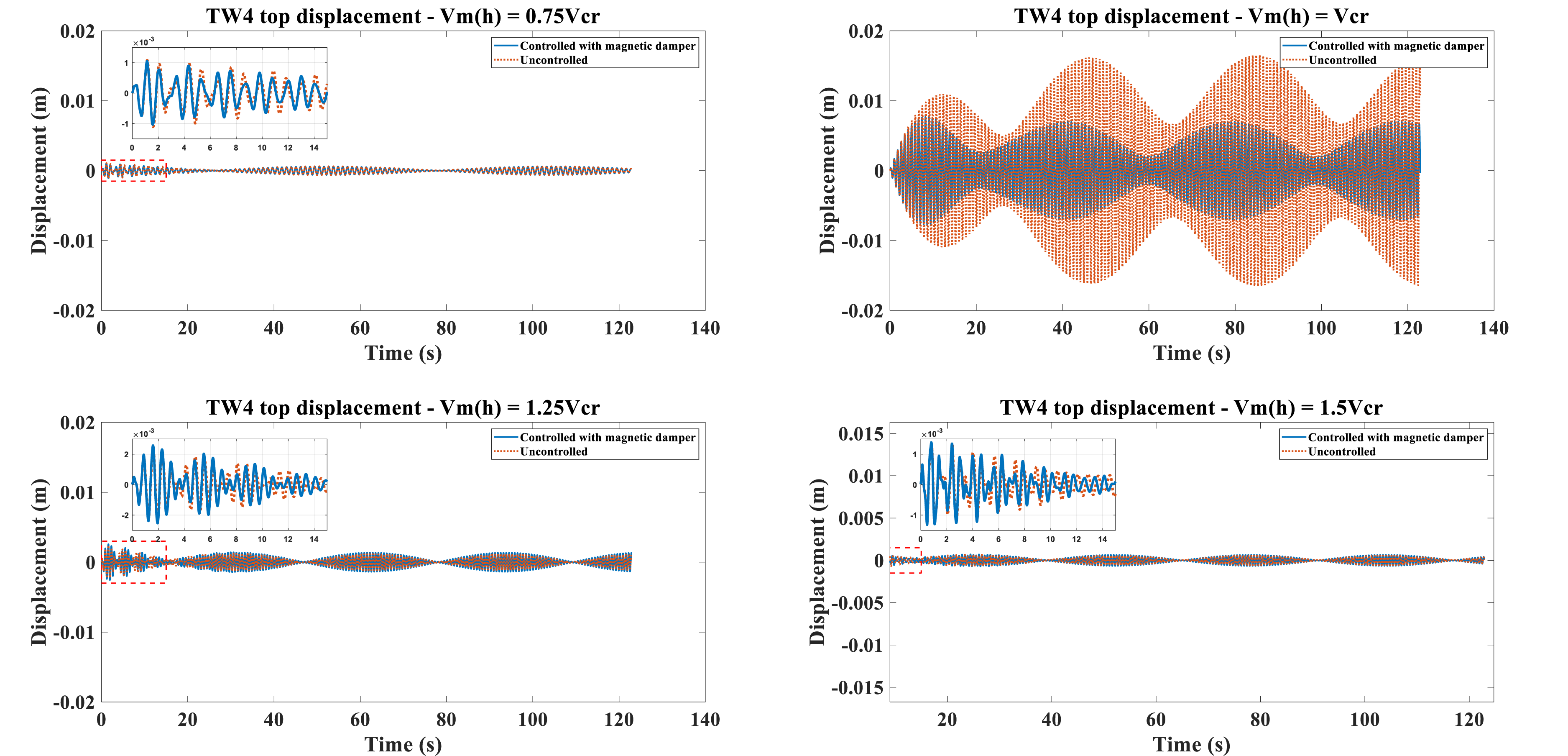
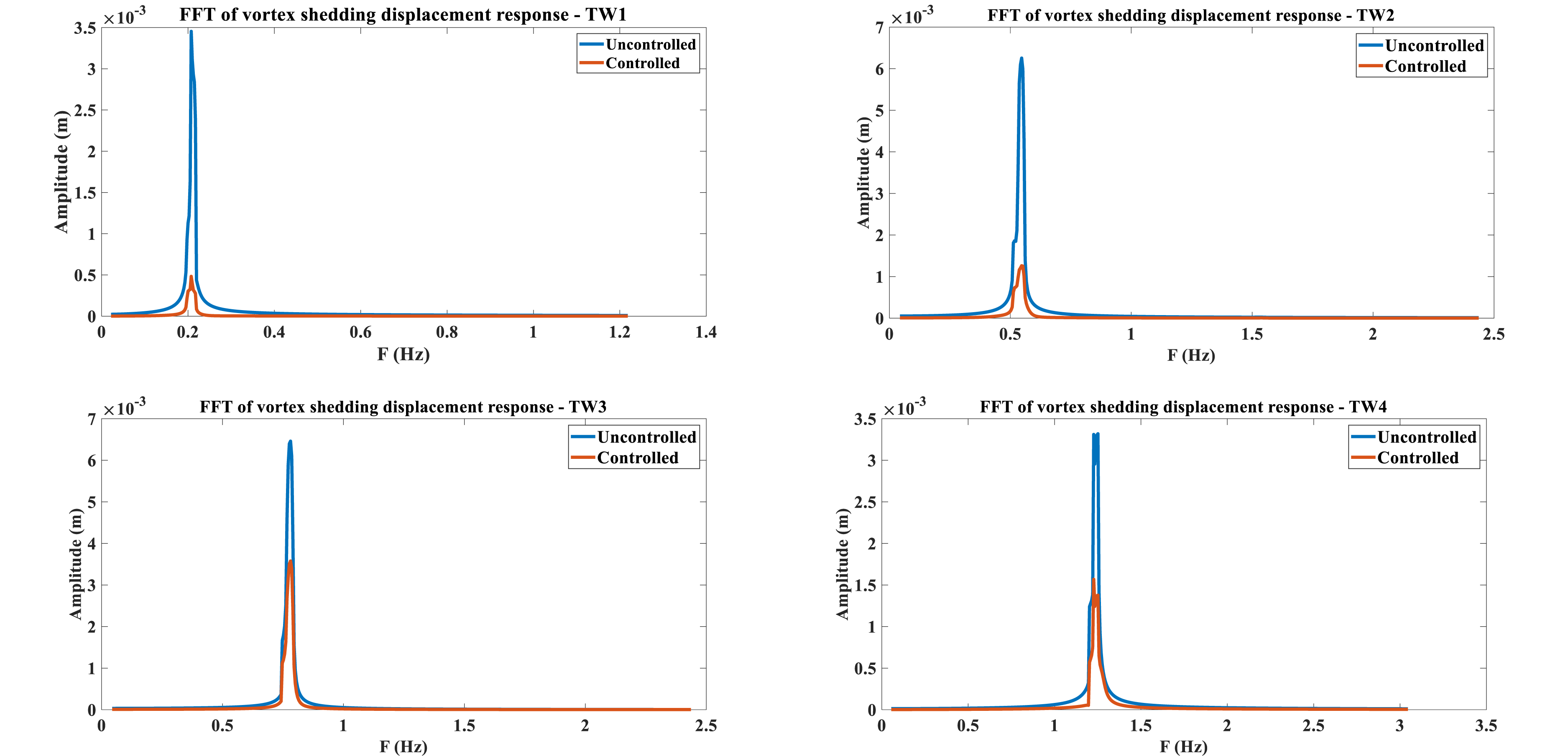
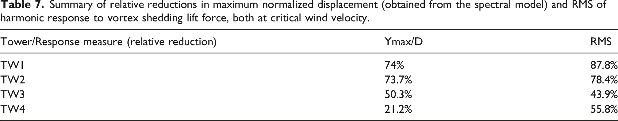
The towers’ top response time history due to harmonic lift force at different tower top wind velocities and resonance vortex shedding (when Top displacement response of the TW1 case due to vortex shedding harmonic lift force. Top displacement response of the TW2 case due to vortex shedding harmonic lift force. Top displacement response of the TW3 case due to vortex shedding harmonic lift force. Top displacement response of the TW4 case due to vortex shedding harmonic lift force. FFT of displacement responses at critical wind velocity (shedding frequency). Summary of relative reductions in maximum normalized displacement (obtained from the spectral model) and RMS of harmonic response to vortex shedding lift force, both at critical wind velocity.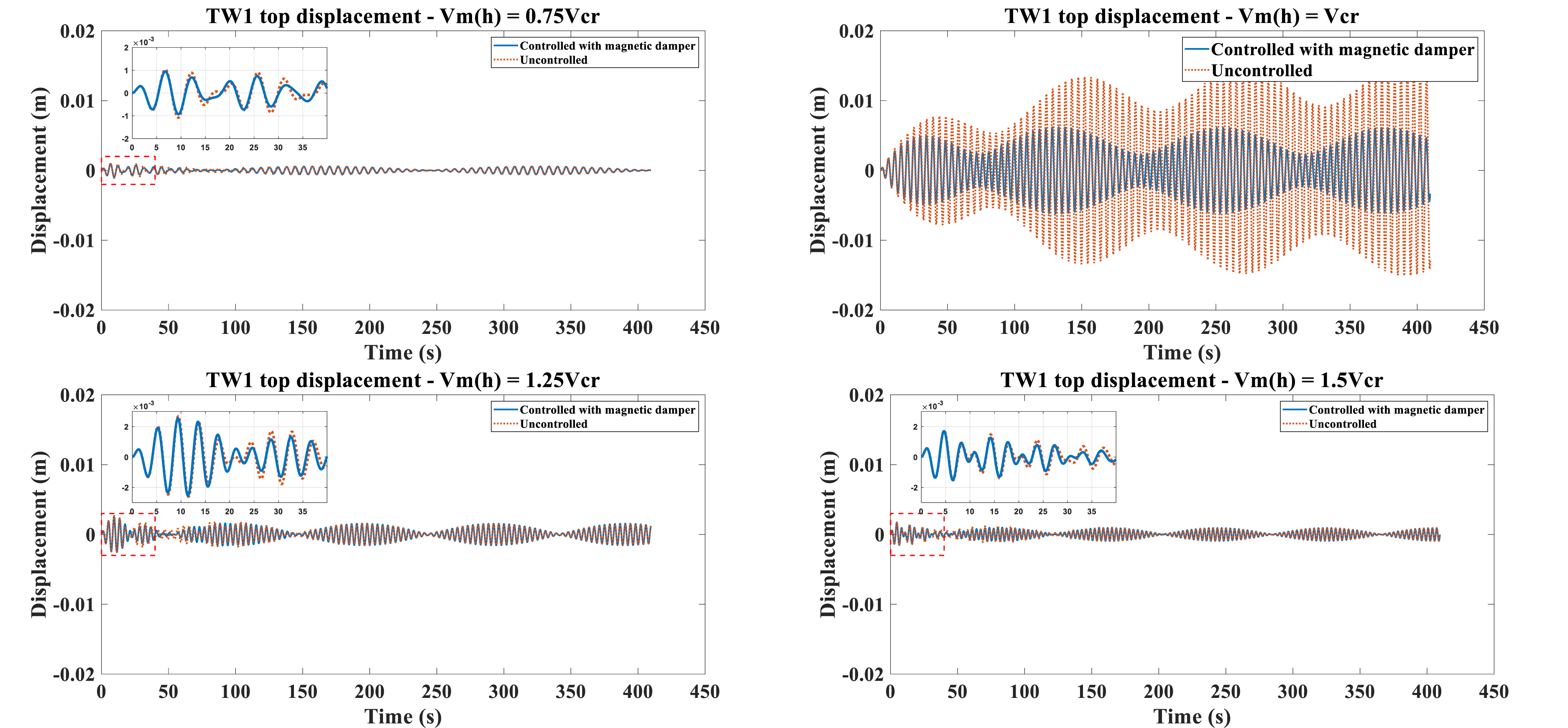
Several limitations of the present study must be acknowledged. The feasibility of manufacturing permanent magnets of the assumed dimensions remains unconfirmed, and no experimental validation of the integrated spectral VIV and magnetic damper framework has been performed. The current findings are therefore contingent upon the assumptions inherent in the numerical and analytical models employed. High-fidelity three-dimensional numerical investigations or dedicated experimental campaigns would be required to further substantiate the present results.
Conclusions
VIV cross-flow response of the DTU 10 MW RWT tower equipped with a magnetic damper at different installation stages was investigated using a spectral model based on Vickery and Basu. The following conclusions are drawn: • The free oscillation response to initial displacement of TW1 and TW2 cases, equipped with magnetic dampers optimized for each case’s space availability, demonstrated significant response reduction and added total structural damping of 970% and 560%, respectively, which was later used to assess maximum normalized VIV response in the spectral model. The response of TW3 and TW4 exhibited smaller reductions controlled by damper #2 (optimized for TW2), though additional structural damping of 150% and 40% was still observed. Despite a slight increase in damper mass ratio compared to TW2, the magnetic damper’s effectiveness in increasing structural damping suggests a wide effective frequency bandwidth, as the natural frequencies of TW3 and TW4 are considerably higher than TW2. • VIV analysis using the spectral model indicated a strong influence of structural damping on maximum normalized displacement response. TW1 and TW2 showed significant relative reductions in tower top displacement due to added damping, while TW3 and TW4 were less affected, as expected. Nevertheless, the use of a damping device clearly mitigates VIV response of WTTs, even during tower erection and nacelle-rotor assembly. VIV response also increases at lower turbulence intensities, though the role of added damping remains noticeable across all turbulence levels. • Tower response to harmonic lift force at different wind velocities showed that the root mean square (RMS) of TW2 top response at resonance (critical wind velocity) was reduced by 78%, while reductions in other cases ranged down to 44% (TW3). The magnetic damper’s effectiveness in reducing harmonic vibration response further demonstrates its acceptable performance for WTT structural control.
Further studies are recommended, including a detailed, high-fidelity coupled CFD and structural dynamics investigation of VIV in magnetic damper-equipped wind turbine towers, as well as exploration of the damper’s effectiveness in reducing VIV response for blade-tower coupling modes at different blade installation configurations and the potential for VIV occurrence in blades.
Footnotes
Author contributions
Reza Pourjafar: Conceptualization, methodology, software, formal analysis, investigation, writing—original draft, and visualization. Martin Otto Laver Hansen: Conceptualization, resources, writing—review and editing, and supervision. Javad Razzaghi: Writing—review and editing and supervision.
Funding
The authors received no financial support for the research, authorship, and/or publication of this article.
Declaration of conflicting interests
The authors declared no potential conflicts of interest with respect to the research, authorship, and/or publication of this article.
Data Availability Statement
Data will be made available upon reasonable request.
Appendix
The mass, stiffness, and damping matrices, presented in equation (5), are defined as follows,
The nonlinear stiffness terms of equation (5) are defined as:
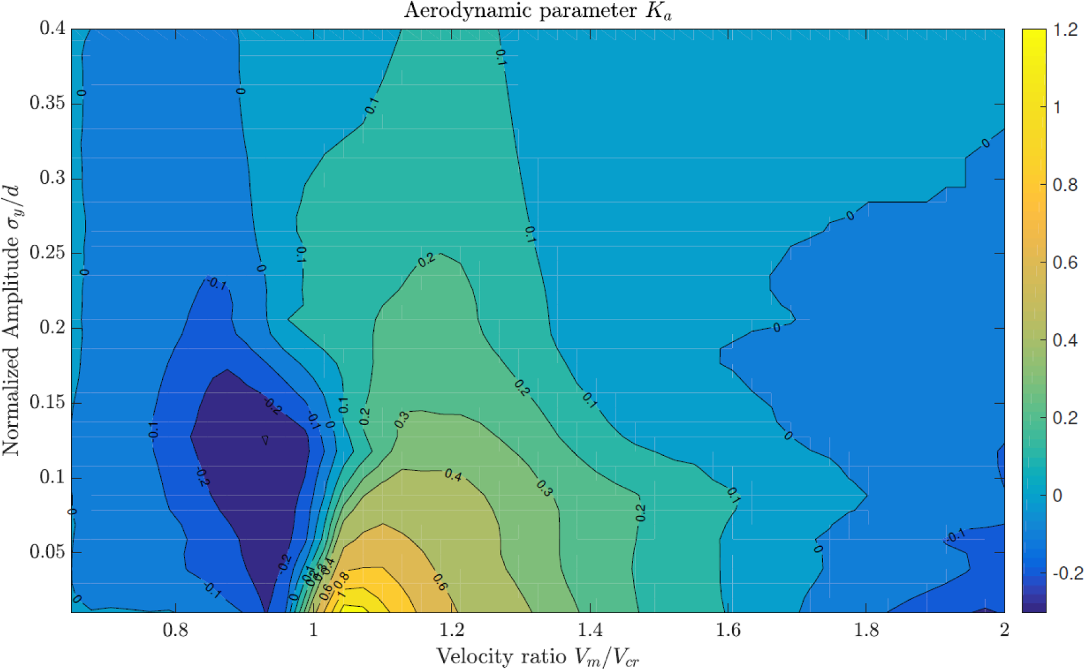
Contour plot of aerodynamic parameter Ka for Vm/Vcr and normalized standard deviation of the maximum deflection (Livanos, 2018).