






Abstract
Research on bladeless wind turbines (BWTs) based on vortex-induced vibration has increased due to the need for sustainable energy and the limitations of conventional wind turbines. BWTs eliminate complex rotating components such as blades and gearboxes, offering a simpler and potentially more reliable design. This study presents a cost-effective numerical and experimental investigation of BWT performance using conic and double frustum masts mounted on a flexible beam. The MATLAB Simulink was used to anlayze the vibration dynamics of the BWT mast, while experimental tests were conducted in a subsonic wind tunnel to analyze the single and double frustum mast. The mast vibrations were recorded using a 60 fps camera, and tip displacement was obtained through an open-source video-based analysis method. The study evaluates vibration frequency, amplitude, and displacement to improve energy harvesting efficiency. Results indicate that the double frustum mast achieves a maximum tip displacement of 0.021 m and exhibits more stable oscillations than the conic mast at a lock-in velocity of 1.7 m/s.
Keywords
Introduction
The increasing global demand for sustainable and low-noise energy solutions, particularly in urban and ecologically sensitive regions, revealed the limitations of conventional horizontal-axis wind turbines (HAWTs), which are characterized by high maintenance efforts, noise, killing of birds, and poor performance at low wind speeds (Mohan et al., 2023). While the horizontal-axis wind turbines are in a mature state of development, the vertical-axis wind turbines (VAWTs) excel in omnidirectional operation. However, both face drawbacks, spurring innovations like the bladeless wind turbine (BWT).
The BWT operates on the principle called vortex shedding that occurs during fluid-solid interaction (FSI). This interaction generates wake patterns known as Karman vortex streets. When the structural frequency of a bluff body aligns with the shedding frequency, the resulting vortex-induced forces influence vibration and oscillatory movement on the body. These oscillations can be converted into usable electrical energy through piezoelectric, electromagnetic, or linear generator systems. The dynamics involved in vortex-induced vibration (VIV) are complex and highly sensitive to the geometry and material of the bluff body as well as the flow parameters, necessitating advanced modeling techniques such as CFD, FSI simulations, and experiments.
Some of the recent studies showed that the flow around the bluff body (Cylindrical) depends on the Reynolds Number, surface roughness, and material of the bluff body Mehmood et al. (2013). Breen et al. (2025) optimized designs numerically, achieving 460 W output with a 0.65 m diameter and 0.8 m mast. Hamdan et al. (2024) used 2-way FSI simulation and real-world data to pinpoint optimal vibration frequency and amplitude for energy harvesting. Elsayed and Farghaly (2022) reported a shedding frequency of 69.81 rad/s and vibration amplitude of 0.0131 mm at 5 m/s (rising to 0.0354 mm at resonance), yielding up to 1.257 mW in sinusoidal power. Experimental and CFD work by Aaiwale et al. (2017), Kumar et al. (2020), and Sundar et al. (2024) demonstrated that optimized BWTs have the potential to match traditional turbine efficiencies and generate 300–400 W/day. Kondekar et al. (2024) integrated design, simulation, and sustainability for environmental gains. Mehmood et al. (2013) optimized piezoelectric harvesting from cylindrical VIV. Yang et al. (2013) showed that tip shapes critically influence galloping-based efficiency. Cajas et al. (2016) advanced FSI simulation tools as part of the shape project for modeling FSIs in bladeless wind turbines. Yáñez Villarreal (2018) explored the fabrication of VIV-based resonant wind generators. Their work highlights the advantages of bladeless wind technology in terms of flexibility and sustainability. Wang et al. (2017) measured 30% noise reduction versus bladed turbines, making BWTs ideal for urban use. Chizfahm et al. (2018) found conical BWTs excel at high speeds and circular cylinders at low speeds. Skop and Balasubramanian (1997) refined VIV modeling with nonlinear wake oscillators, validating configuration via CFD-FEM. Several studies have examined the performance of VIV-based BWT with variation in mast shape. Chizfahm et al. (2018) investigated the performance of BWTs using four different cylindrical configurations, as illustrated in Figure 1. The BWT1 and the BWT2 employed flexible cylinders with equilateral and variable cross-sections, respectively. On the contrary, the BWT3 combined a flexible beam with a rigid cylinder of uniform cross-section, while the BWT4 integrated a flexible beam with a rigid variable cross-section. Yazdi (2018) applied nonlinear model predictive control (NMPC) to optimize BWTs, with simulations showing enhanced energy extraction through dynamic parameter adjustments. Bardakjian et al. (2017) experimentally compared HAWTs and BWTs, finding the latter 20% less efficient but simpler. The bladeless wind turbines; (a) BWT1, (b) BWT2, (c) BWT3, and (d) BWT4 (Chizfahm et al., 2018).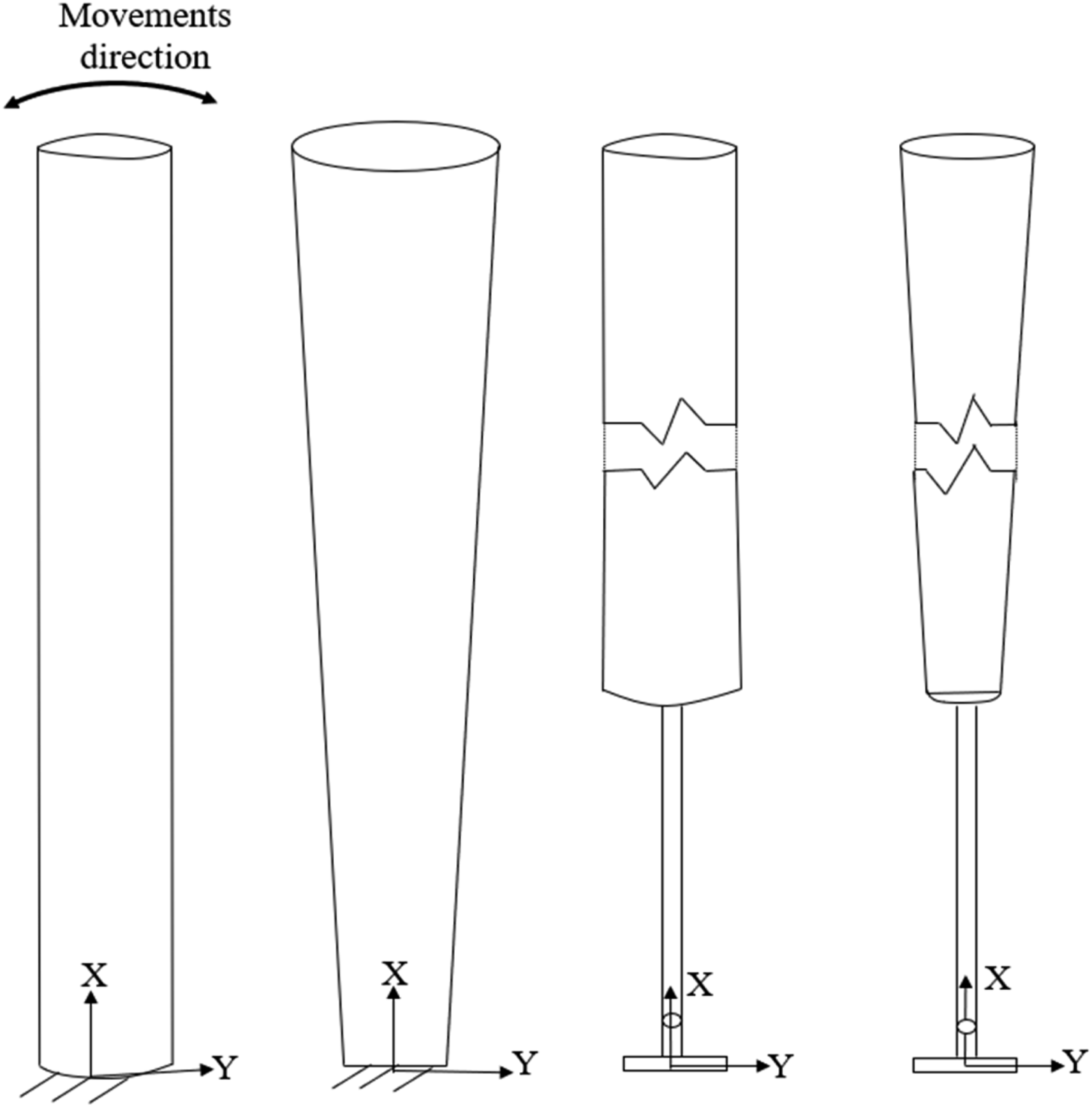
Recent advances feature Bahadur et al. (2022), whose tunable vortex BWT outperformed conventional designs above 4.22 m/s, generating 1105 mW (RMS). Younis et al. (2022), validated a piezoelectric BWT via aeroelastic modeling and FEM. Manolas et al. (2022), used semi-empirical methods to identify VIV-susceptible structural modes and Mohamed et al. (2025), found that the there is an improvement of efficiency by 55.2% at 7 m/s by using composite materials, tunable mass, and effective length adjustment.
Bladeless wind turbine and its limitations
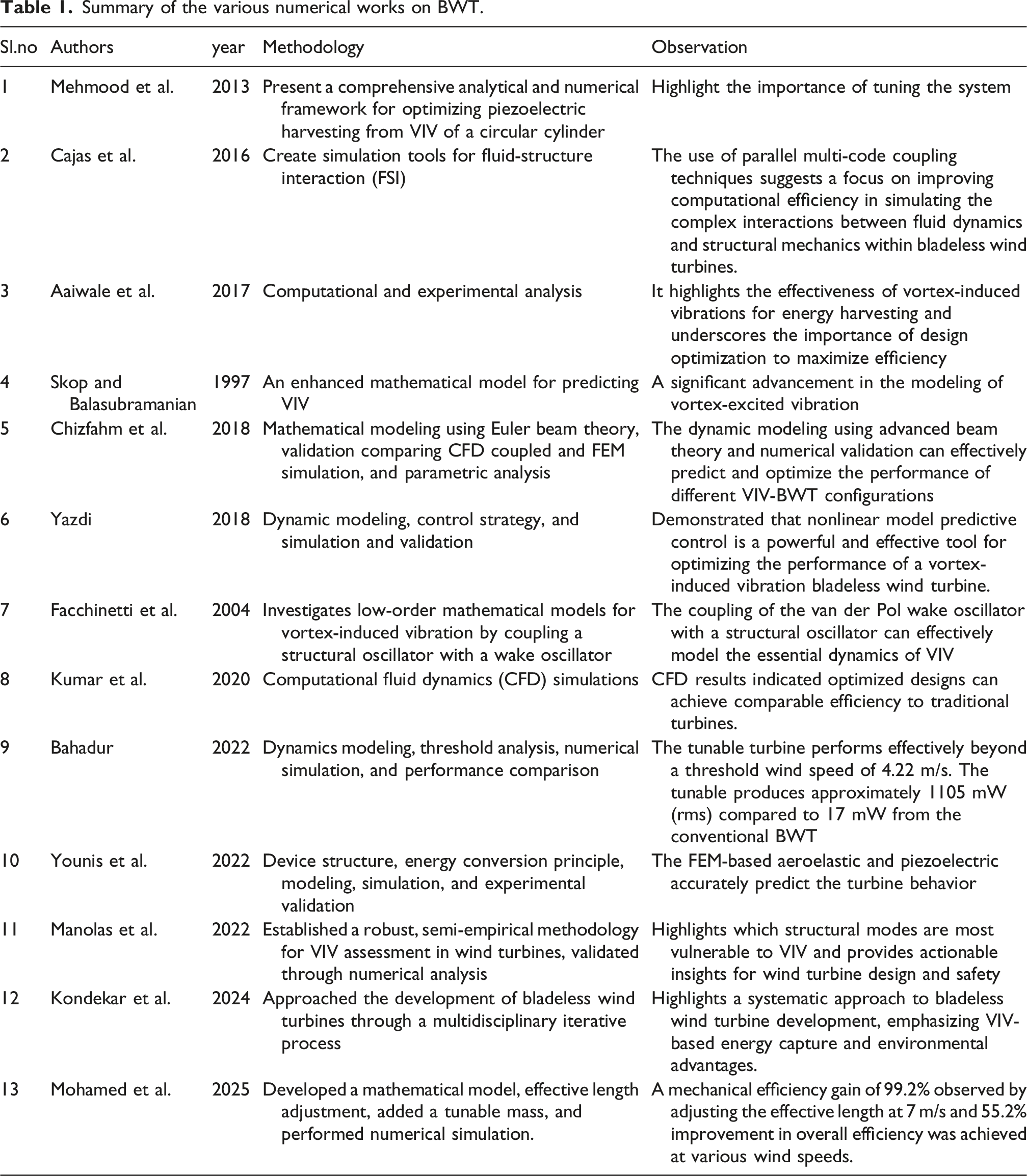
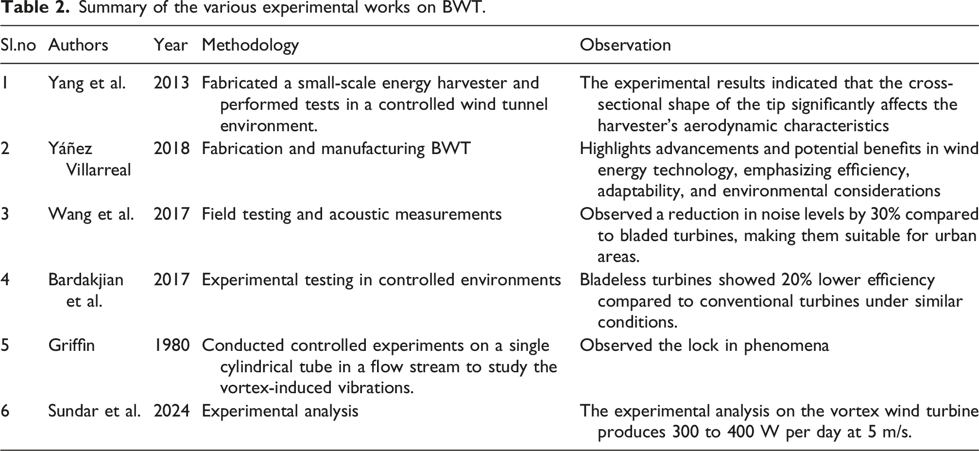
The working principle of a bladeless wind turbine is based on the phenomenon of fluid structural interaction (FSI) in classical fluid mechanics. However, their application in energy harvesting systems remains in an early developing stage, resulting in several critical shortcomings. Some of the key challenges include lower energy efficiency and power output compared to conventional bladed wind turbines, structural fatigue due to oscillatory stresses, and scalability limitations for large-scale deployment. Beyond these primary hurdles, several limitations that complicate research in the BWT, such as narrow lock-in range, a phenomenon where vortex shedding frequency matches with the structural frequency at a specific wind speed, resulting in a significant drop in power generation outside this range. Furthermore, real-world experimental data are scarce, challenges in the implementation of low-power control systems, and trade-off in optimization. Figure 2 shows the schematic diagram of the existing vortex bladeless wind turbine. Bladeless wind turbines offer several advantages over traditional horizontal and vertical axis wind turbines, both offshore and onshore (Chizfahm et al., 2018). Bladeless wind turbines produce significantly less noise compared to traditional wind turbines, making them more suitable for urban and residential areas. The absence of blades minimizes the risk to birds and bats, addressing a common environmental concern associated with traditional wind turbines (Mohamed et al., 2025). With fewer moving parts, bladeless turbines require less maintenance and are less prone to mechanical failure, potentially leading to lower long-term operational costs. Bladeless turbines are often less visually intrusive, which can help mitigate public opposition to wind energy projects, especially in scenic or residential areas. Initial costs for bladeless turbines can be lower due to simpler construction. Their smaller footprint can also reduce land use and installation costs (Wulandana et al., 2022). These turbines can be easily scaled and integrated into various environments, including urban landscapes, where traditional turbines might be impractical. The summary of the various works on BWTs is reported in Tables 1 and 2. Schematic diagram of VIV-based BWT (Mohamed et al., 2025). Summary of the various numerical works on BWT. Summary of the various experimental works on BWT.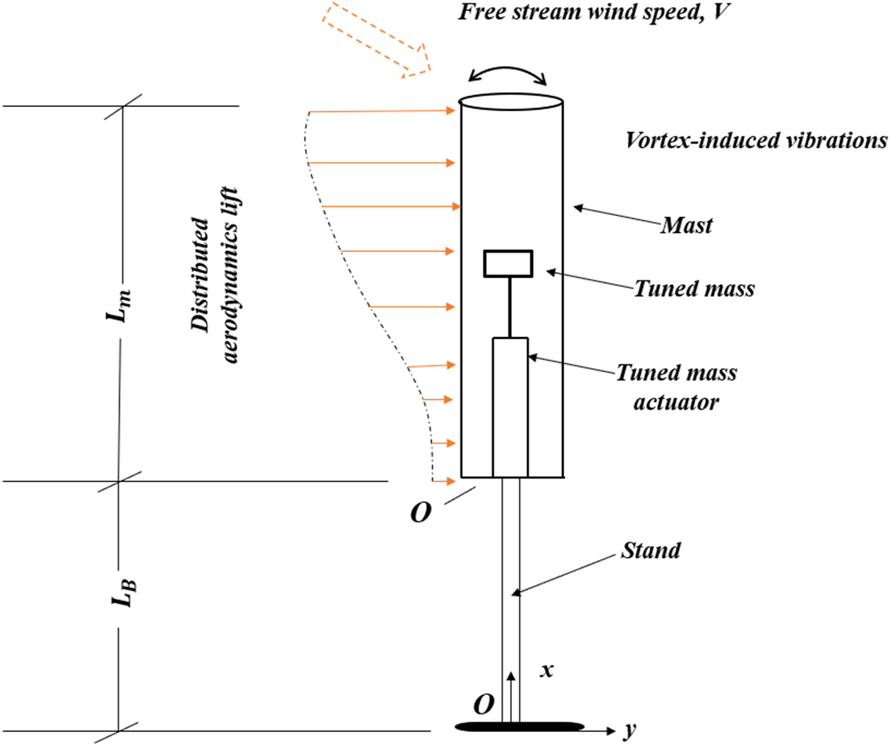
The flow around a bladeless wind turbine is inherently unsteady, marked by flow separation and vortex shedding, vortex-induced vibrations, and transverse oscillations of the structure. To precisely capture the Von Kármán vortex street with alternating vortices, periodically varying pressure on the structure surface, kinetic energy of oscillating flow due to vortex shedding, aerodynamics forces and FSI, the numerical methods such as the finite volume method (FVM), finite difference method (FDM), and finite element method (FEM) are used for discretizing the governing equations around the BWT (Araneo et al., 2019). However, FVM and FEM are widely used for computational fluid dynamics (CFD) simulations of VIV in bladeless wind turbines due to their robustness in handling unsteady flow, structural dynamics, and FSI-based vibration analysis (Ajayi et al., 2023; Alomari et al., 2019; Mohammadi et al., 2018). The commercial FVM-based solvers (e.g., ANSYS FLUENT, CFX, STAR-CCM+) have proven their effectiveness in predicting flow physics. Further, the turbulence model selection—such as Spalart and Allmaras, Realizable k–ε, Renormalization Group (RNG) k–ε, Shear Stress Transport (SST) k–ω, v 2 –f, Large Eddy Simulation (LES), Hybrid Reynolds-Averaged Navier-Stokes (RANS)-LES is critical for accurate wake resolution (Alom et al., 2021; Spalart and Allmaras, 1992). The LES resolves large turbulent structures while modeling smaller scales, offering high accuracy for unsteady flows but at a high computational cost (Ding et al., 2016; Francis et al., 2022; Spalart and Allmaras 1992). Additionally, fine grid resolution near the rotor is essential for capturing vortical structures and ensuring simulation fidelity (Launder and Spalding, 1974). FSI approaches are generally classified into one-way and two-way coupling models. The method is known as one-way FSI if the fluid flow analysis does not incorporate input from structural analysis. The method is known as two-way FSI if the structural analysis feedback is also included. Large structural deformations and their interactions with the flow field, such as VIV, are often handled using two-way FSI (Borouji and Nishino, 2019; Tezduyar and Osawa, 2001).
Problem statement
Traditional wind turbines with blades often face issues such as high maintenance needs, noise, safety concerns for birds, and poor performance at low wind speeds. BWTs, which work on VIV instead of rotation, offer a lower, simpler, and potentially more sustainable solution. However, their design is still not well understood, especially the role of mast geometry and shape in improving energy capture and stability.
Research gap
Although wind energy has been extensively studied through conventional bladed turbines, research on bladeless wind turbines (BWTs) is still at a very early stage. Most existing studies have focused on fundamental concepts and proof-of-design prototypes, with limited attention to detailed performance optimization. In particular, the influence of geometric parameters such as shape, size, and configuration on the efficiency and stability of BWTs has not been systematically explored. Furthermore, very few studies combine numerical simulations, structural analysis, and experimental validation to provide a comprehensive understanding of their performance. This lack of integrated research creates a gap in knowledge, making it difficult to assess the true potential of BWTs as a practical and scalable renewable energy technology.
Objective of the present analysis
In the present study, a novel convergent–divergent double frustum mast VIV bladeless wind turbine (BWT) has been designed to evaluate its efficiency under low wind speed conditions. Its performance was first examined through a simulation framework developed in MATLAB Simulink, which provided useful insights into system behavior. To validate the results, a low-cost laboratory-scale experimental setup was constructed by integrating the proposed design with a subsonic wind tunnel, where controlled wind velocities were generated artificially. The performance of the double frustum mast BWT was then compared with that of a conventional single conical BWT to assess improvements in energy capture and stability. Furthermore, the lock-in range for both mast configurations was identified, and additional investigations were conducted to examine the response of the double frustum mast with and without an energy harvesting unit. The double frustum mast shows the higher tip deflection, displacement, and power output at lock-in velocity. Hence, the double frustum mast may be used for small-scale power production in rural areas.
Methodology
The performance of bladeless wind turbines with different geometric variations was evaluated through a combination of numerical simulation and experimental testing. Specifically, two mast geometries were investigated: a conic mast and a double frustum mast. The tip displacement was observed using the high-speed camera, and its response has been evaluated using Tracker, an open-source video analyzing software.
Simulation
A Simulink model was developed to simulate the dynamic behavior of the bladeless wind turbine. The model incorporates the equation of motion, representing the lift force (1) action on the mast due to vortex shedding, given by

The mast, which is subjected on the flexible beam, will oscillate at the Vortex shedding Frequency, and maximum deflection will take place during lock-in velocity, where the structural natural frequency aligns with the vortex shedding frequency. The vortex shedding frequency is obtained by
The theoretical equation for the natural frequency of the beam is given by
The BWT consists of the mast, which is mounted on the flexible beam, in which the tip displacement is influenced by the aerodynamic force acting perpendicularly to the flow. The structure equation of motion is modeled as the simple mass-spring system obtained by

The Simulation block is represented in Figure 3. Simulation block diagram.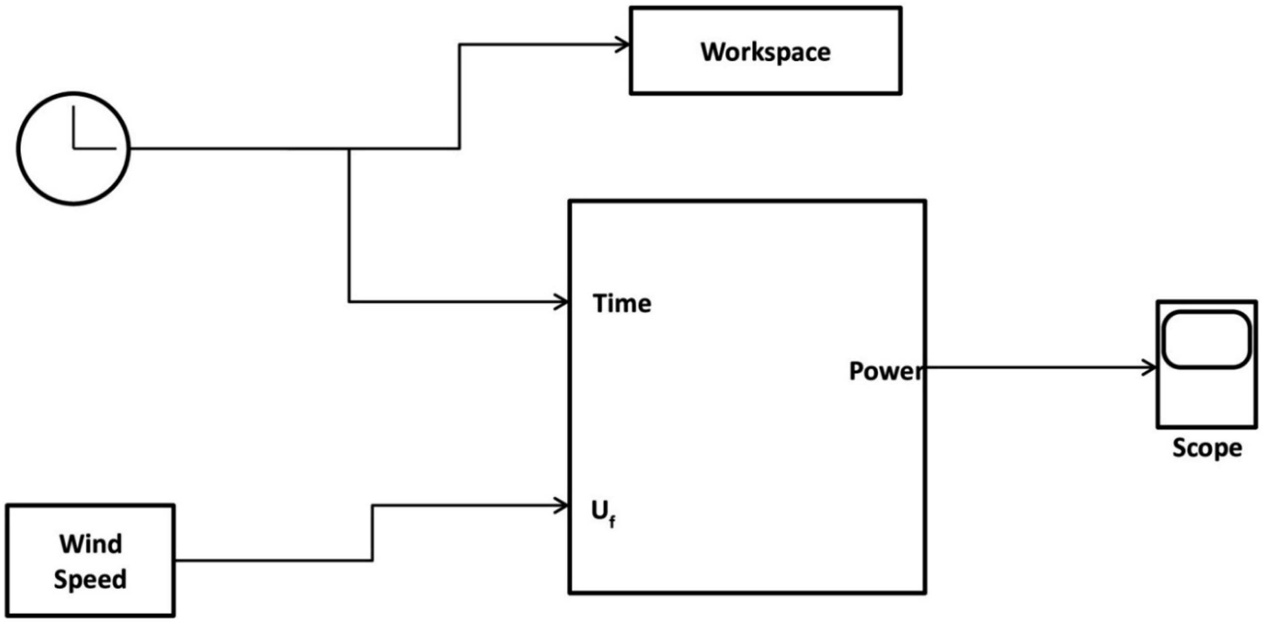
For BWT work damping ratio estimation is crucial because the device operates near vortex-induced vibration (VIV) resonance. Bladeless wind turbines typically operate in low damping range from 0.01 to 0.05 to allow large oscillation amplitude. Also, the aerodynamic damping defends on reduced velocity and Strouhal number. Near the lock-in region, the aerodynamic damping may become negative (self-excitation) and the system oscillates at resonance (Meirovitch, 2001).
The expression of and damping ratio (
Development of bladeless wind turbine
The oscillating mast (A) is designed to capture wind energy and is typically constructed from strong, lightweight materials such as carbon fiber or fiberglass. For the prototype model, paper cup material is used for the mast due to its lightweight nature, making it compatible with the flexible beam.
In a BWT (Figure 4), the beam supports and absorbs the forces induced by the oscillating mast. When the oscillation frequency of the mast matches the natural frequency of the beam, resonance occurs, causing the beam to vibrate. This vibrational motion is then harnessed for power generation. An air core generator (B) is employed in this prototype to reduce frictional or magnetic forces that could dampen or lock the vibrations of the system. The use of an air core coil improves efficiency by minimizing energy losses due to hysteresis and eddy currents, ensuring smoother and more consistent oscillations. Its lightweight design also complements the overall structural dynamics of the bladeless wind turbine, reducing unwanted interference with the resonant behavior of the flexible beam. A 40 swg and 2500 turns winding. Ring neodymium magnets (C) are integrated into the bladeless wind turbine to enhance the electromagnetic induction process due to their strong magnetic field. Their high energy density allows for more efficient power generation by maximizing the interaction between the oscillating mast and the induction coil. Schematic of the proposed bladeless wind turbine.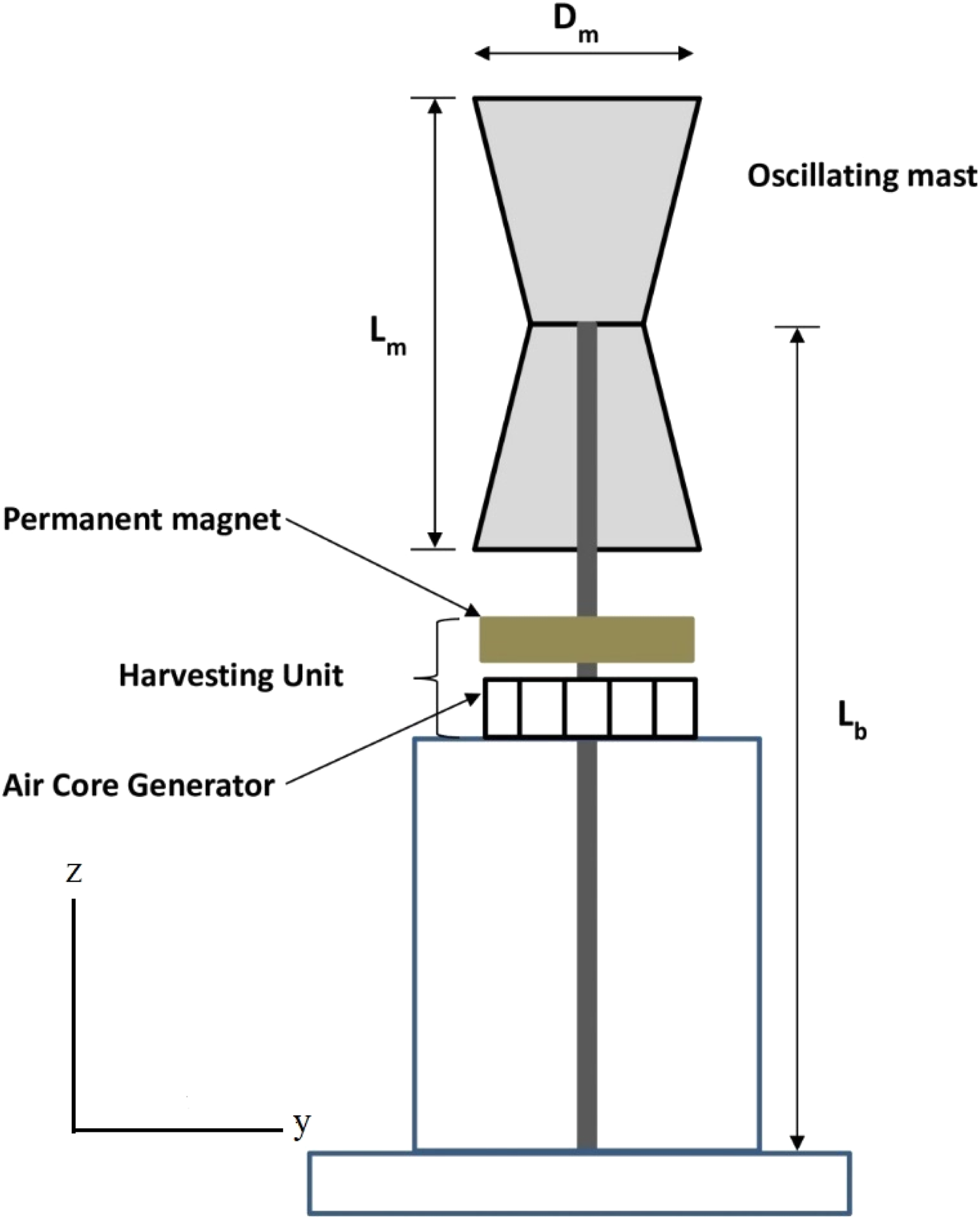
Additionally, their compact and lightweight design ensures minimal impact on the overall system’s mass and vibrational dynamics, while providing consistent and reliable magnetic performance even in low-wind conditions.
Wind tunnel test
A lab-scale experimental investigation was carried out using the subsonic wind tunnel. The schematic and photographic view of the wind tunnel with its dimensions shown in Figure 5 and the setup illustrated in Figure 6, respectively. The wind tunnel turbulence intensity has been varied in the range of 0.5% to 2% in the case of the open circuit tunnel. The blockage ratio, which is defined as the ratio of the model’s projected frontal area to the test section area of the wind tunnel, is calculated to be 13%, which exceeds the suggested value, that is, below 10% (He et al., 2022). According to Pope and Harper (1996), the blockage correction factor is used for testing small-scale wind turbines under a closed test section and has been correlated with dependable parameters such as wind speed, dynamic pressure, and Reynolds number, but this blockage correction factor is not applicable in an open test section under dynamic loading. The study of the correction factor in a drag-based vertical axis wind turbine in an open test section is found by Roy and Saha (2014); however, the blockage correction factor for BWT has not yet been studied till date under either an open or closed type test section. Subsonic wind tunnel (all dimension are in mm). Photographic view of the subsonic laboratory scale wind tunnel setup.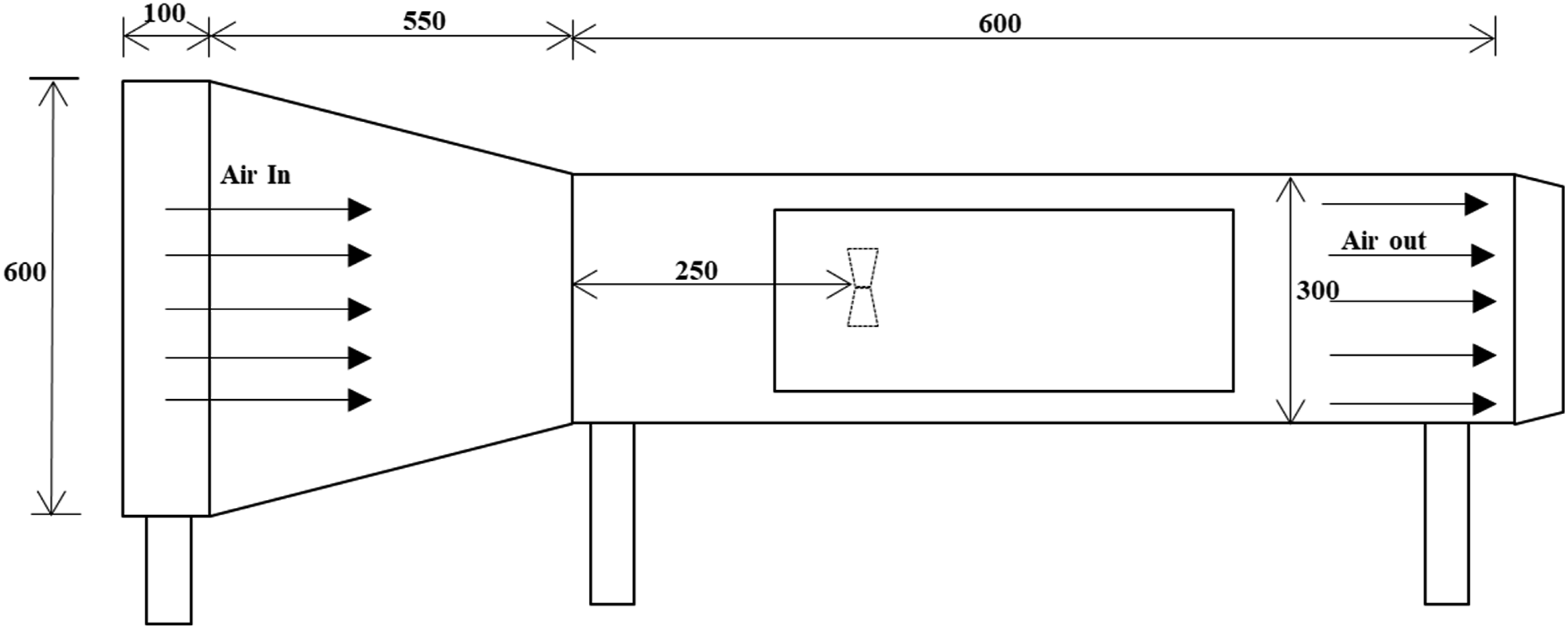
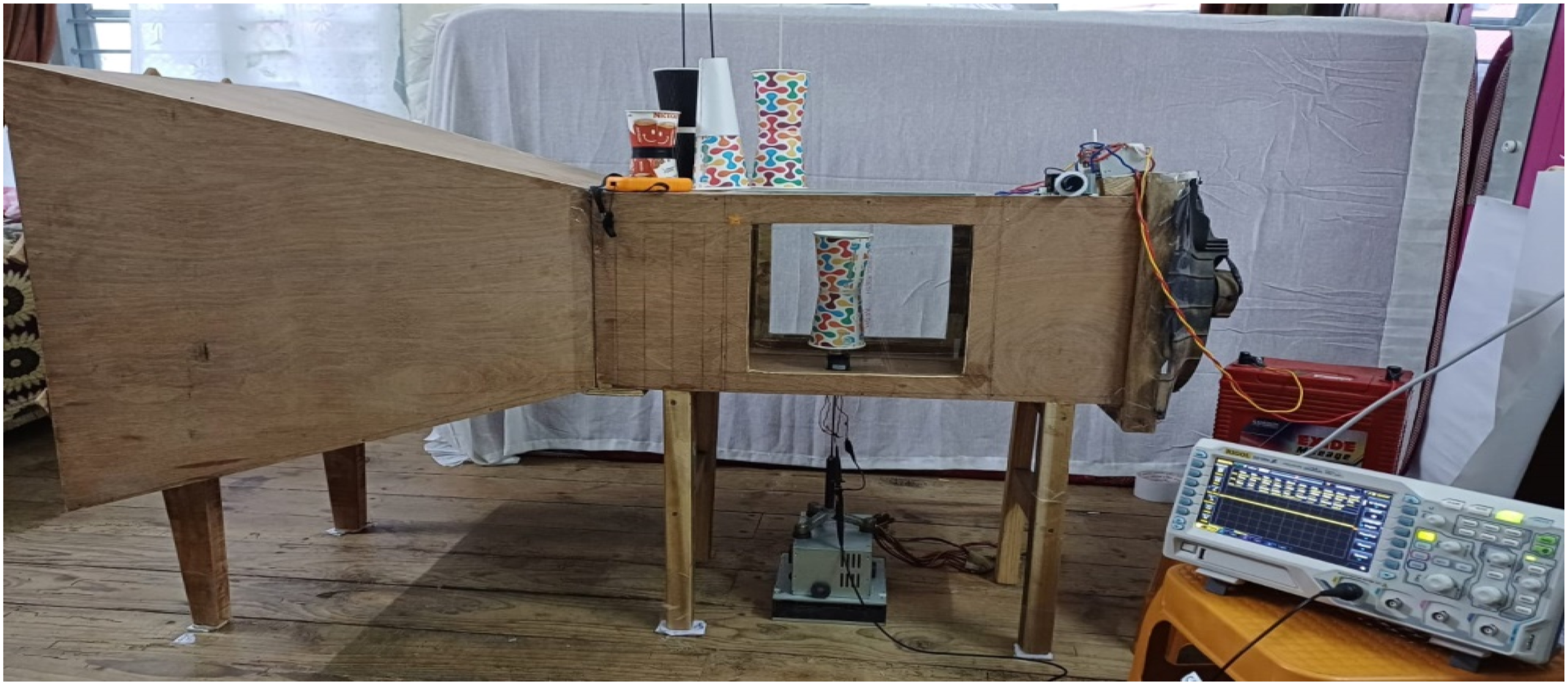
The main objective of the wind tunnel within this study is to streamline and generate a consistent air flow velocity at the point of the test mast. The mast was placed at a designated location within the test chamber of the wind tunnel, and the wind velocity was gradually increased until the “lock-in” velocity was reached. The lock-in velocity represents the condition at which the maximum displacement of the mast occurs, wherein the frequency of the vortex is synchronized with the natural structural frequency.
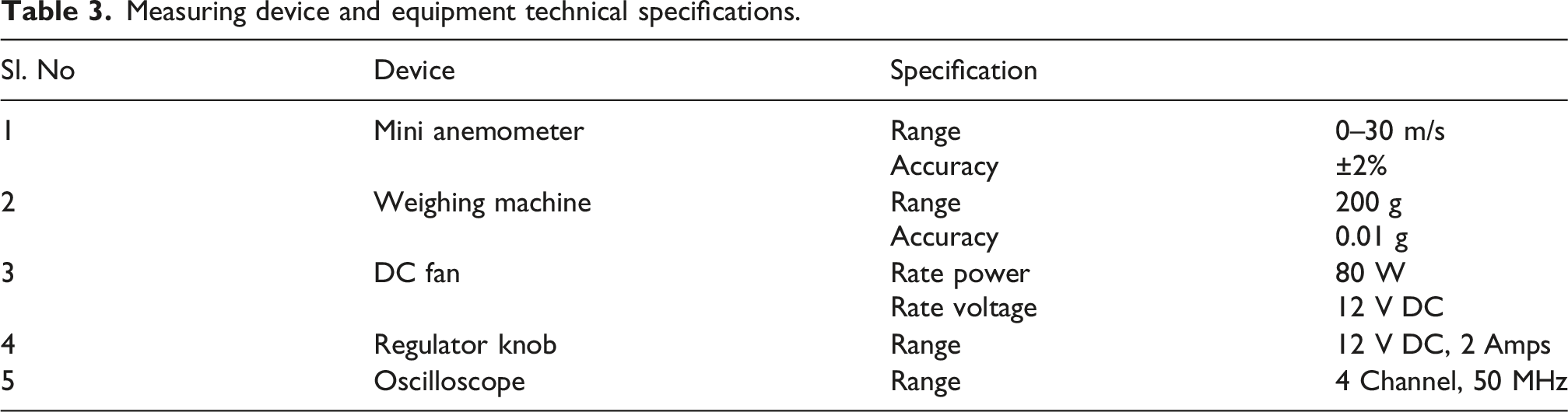
The anemometer was positioned exactly where the mast was placed to monitor wind velocity and was accordingly calibrated in the regulator knob before the experiment was conducted. This is to ensure uninterrupted and allow precise air flow through the mast, free from obstruction.
Measuring device and equipment technical specifications.
Turbine power estimation
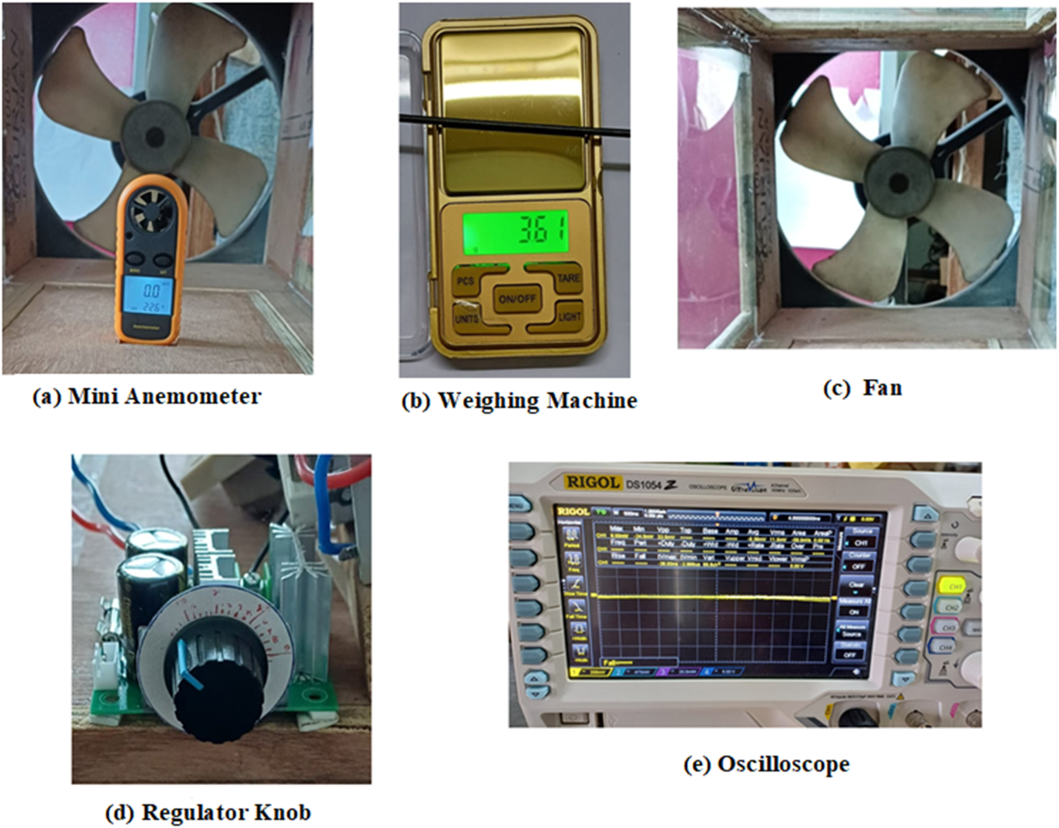
Power is calculated both for experimental and simulation data. The actual power output is nonlinear because of the continuous variation of air flow conditions and the resulting changes in aerodynamic forces such as lift, drag, and vibration; a simplified linear approach is used. Various measuring devices are shown in Figure 7. This simplification is necessary because not all forces are measured directly during the experiment, and the equation of power output is represented below (Manwell et al., 2009; Mohammed et al., 2025; Rathod et al., 2019; Zhao et al., 2014): Measuring device and equipment technical specification.
Tracker
Tracker is a popular open-source video-based analysis (VBA) tool that is helpful in analyzing Vibration, displacement, and frequencies of the dynamic system. In this study, experimental analysis is done using Tracker as shown in Figure 8. The tip displacement of the beam is analyzed using a high frame rate video of (60 fps) recorded with a fixed camera aligned to the turbine motion plane. A scale reference was placed in the video for spatial calibration. The topmost part of the turbine was manually tracking frame-by-frame capture tip deflection of the beam due to VIV. Top view of mast video base analysis tool.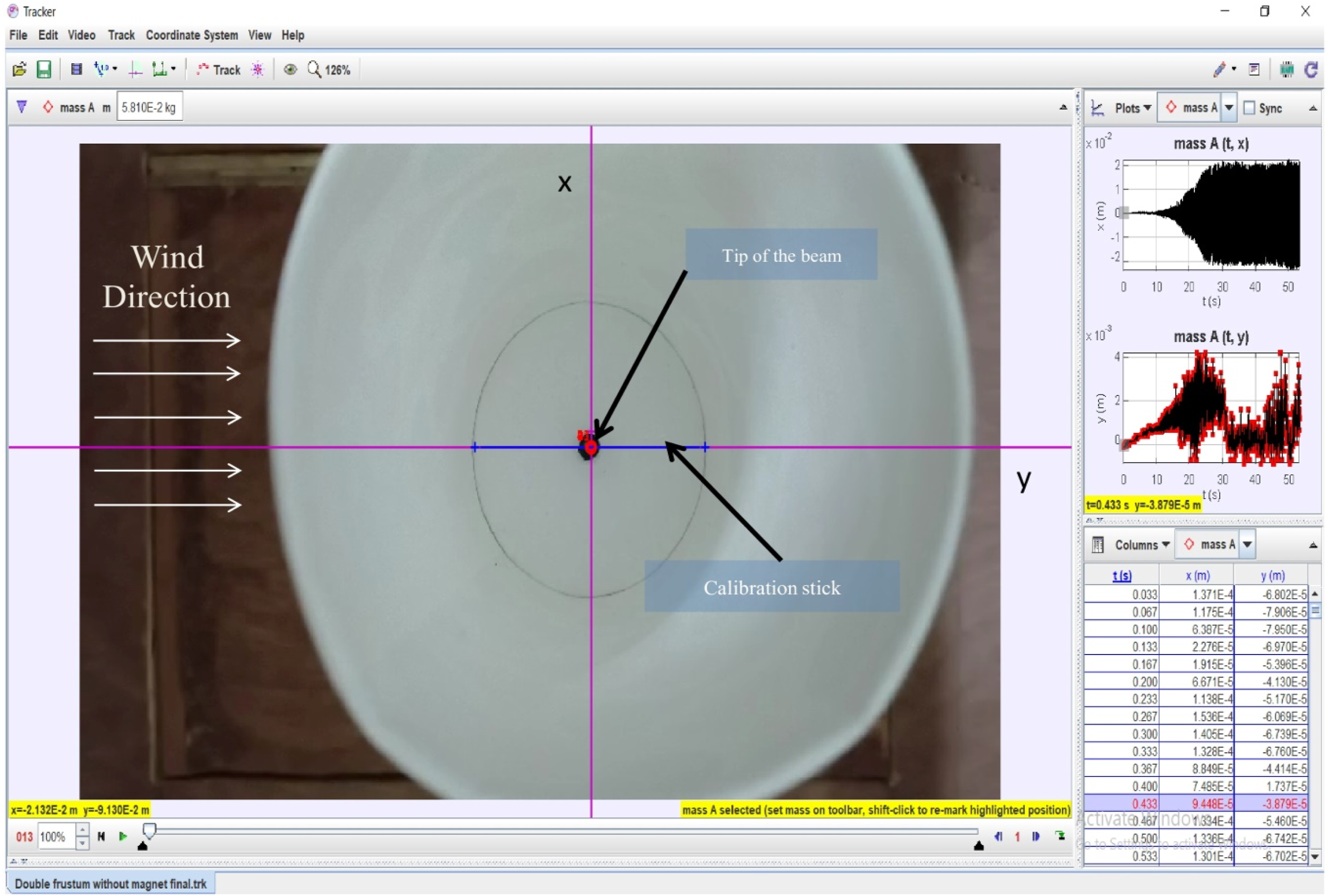
Results and discussion
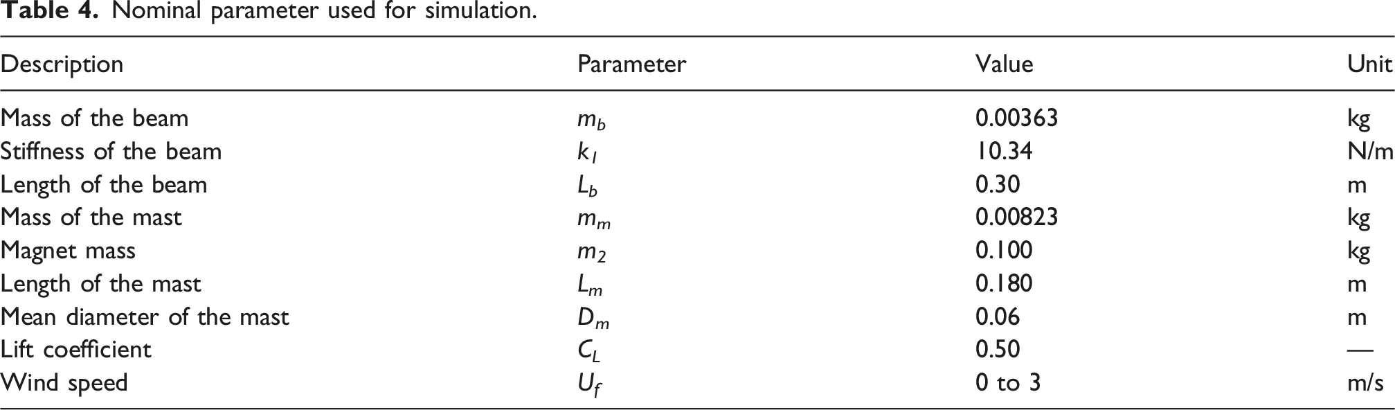
Nominal parameter used for simulation.
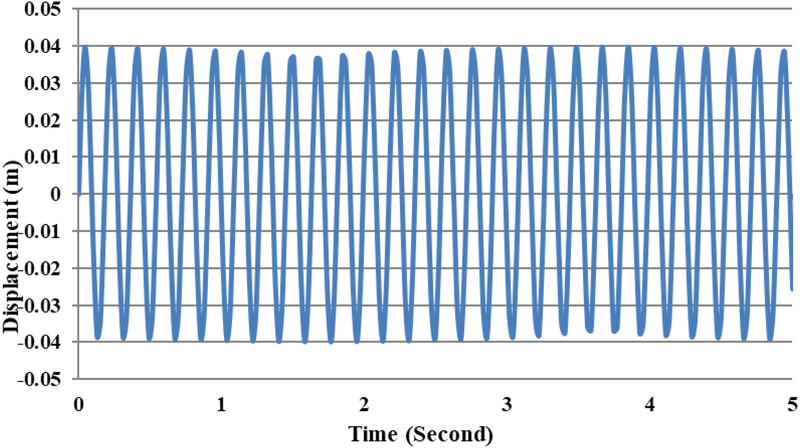
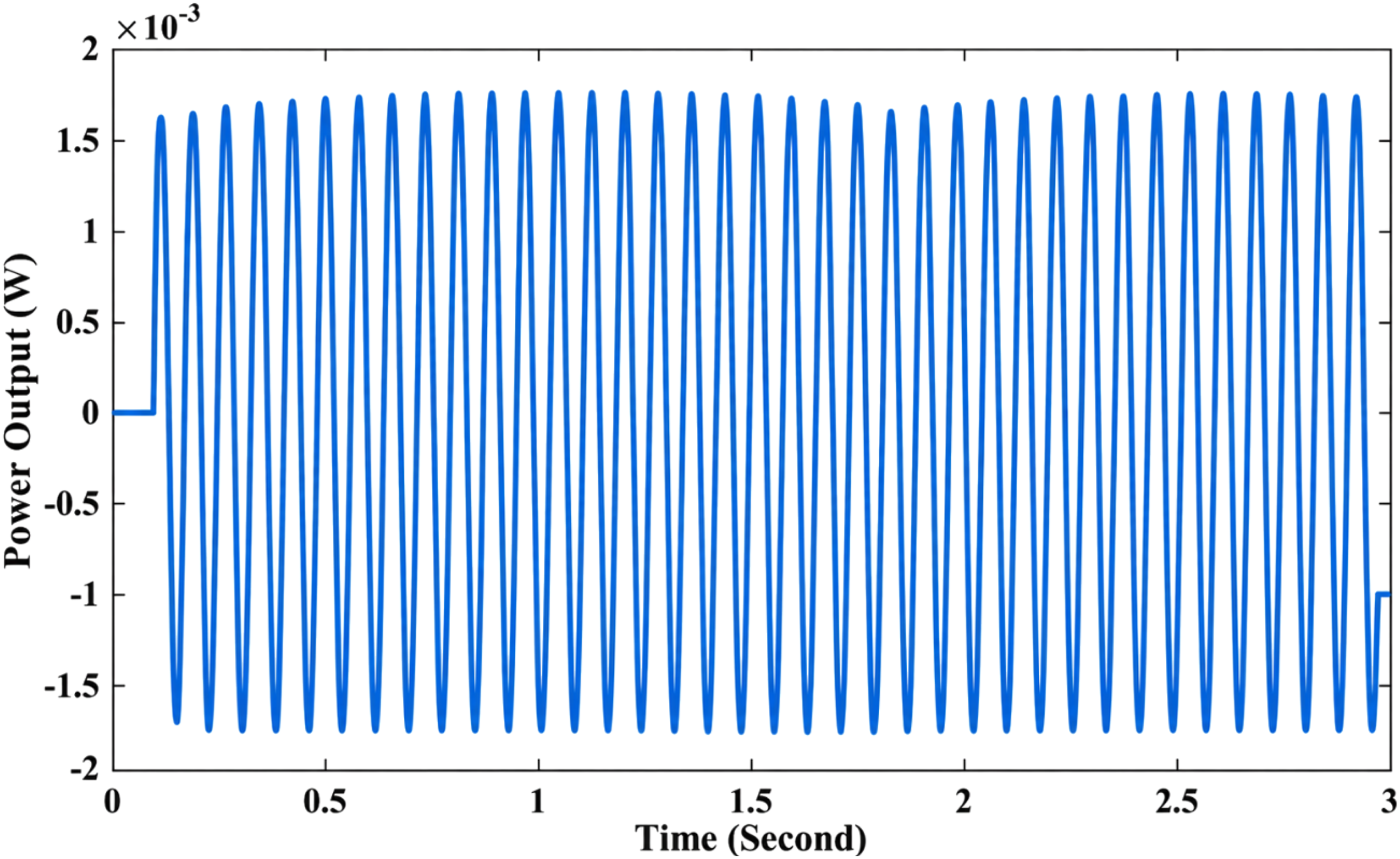
The simulation results provide valuable insights into the dynamic behavior of the DFM-BWT with varying wind speed. Figure 9 illustrates the turbine’s deflection in the x-direction at 2.3 m/s, indicating significant motion in response to wind excitation. This transverse displacement is necessary to determine since it is the primary indicator for design, safety, efficiency, and suitability for energy generation. In Figure 10, the results showed that the turbine attained the lock-in range, indicating the vortex-shedding frequency aligns with the natural frequency of the beam, whereas Figure 11 shows the power output of a turbine at a lock-in velocity of 1.7 m/s. The oscillatory nature of the curve indicates unsteady power generation, which is common in BWT due to the nonlinear behavior of fluid-structure interaction. Tip displacement of DFM BWT at 2.3 m/s wind speed. Tip displacement of the DFM BWT at lock-in velocity, 1.7 m/s. Power generated by the DFM BWT at lock-in velocity, 1.7 m/s.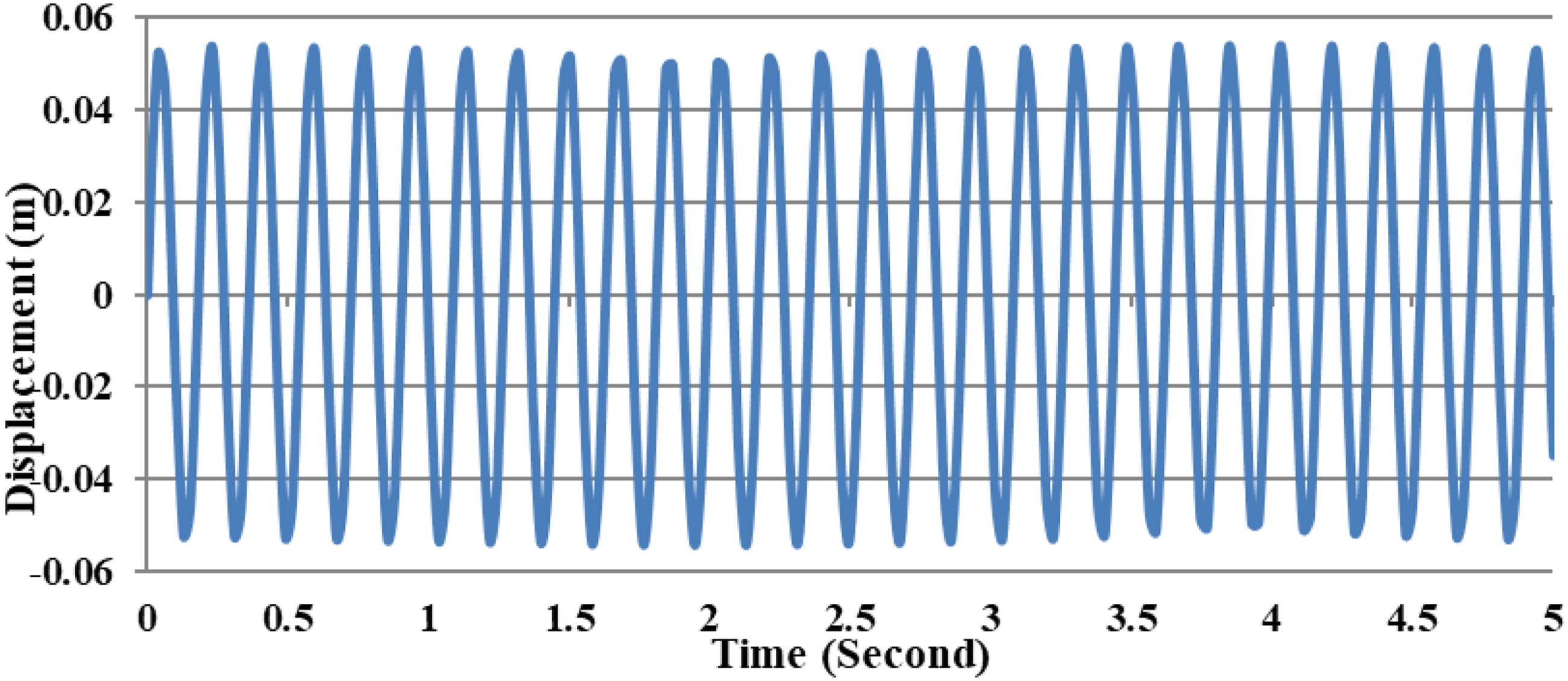
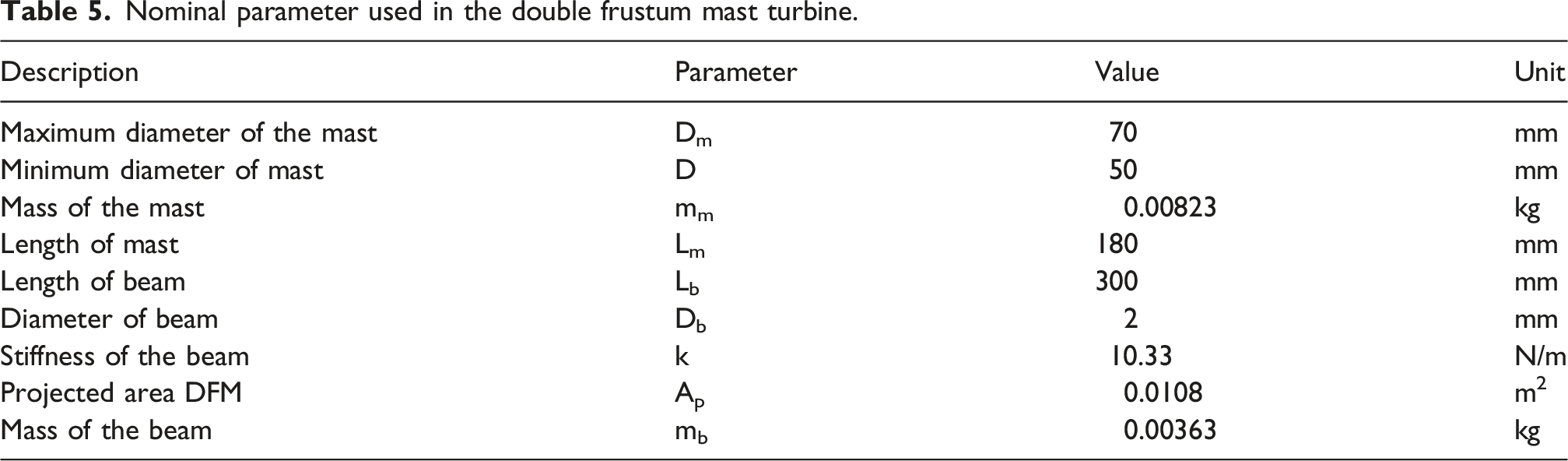
Nominal parameter used in the double frustum mast turbine.
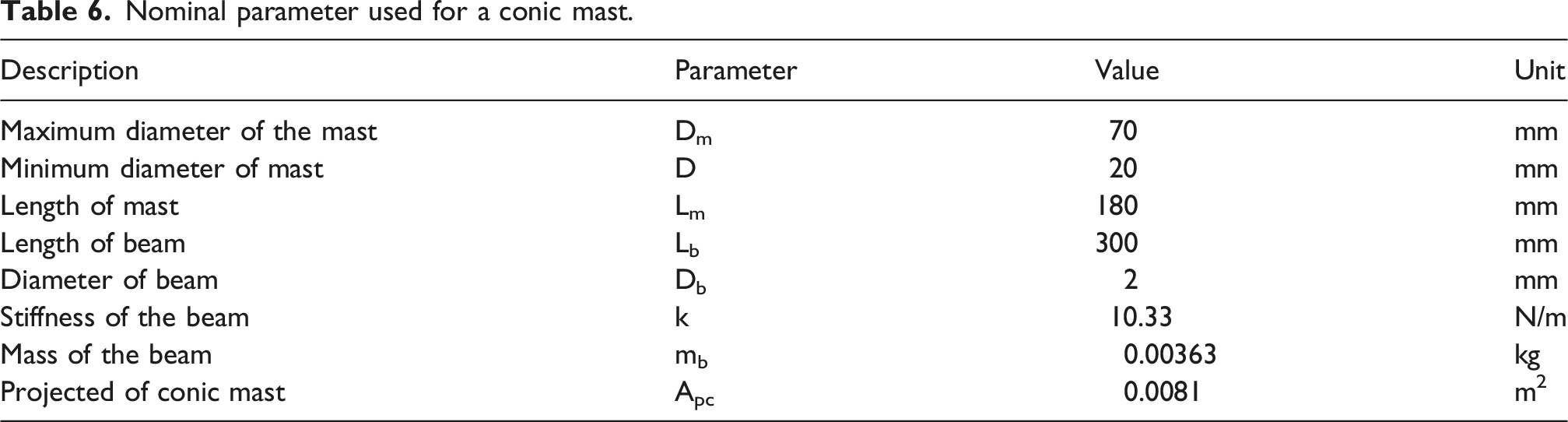
Nominal parameter used for a conic mast.
Performance testing of the conical BWT and the DFM-BWT was conducted in a laboratory-scale wind tunnel; both configurations were evaluated under identical test conditions. The turbines were positioned at 0.25 m from the entrance of the test section, and the wind speed was gradually increased by regulating the voltage of the fan motor, continuing until the turbine reached maximum displacement. A high-resolution camera (60fps) was mounted at the top of the test section’s transparent glass to record the beam tip displacement. Simultaneously, current and voltage outputs were monitored on an oscilloscope and a multimeter, respectively. The tip displacement of conical BWT and DFM-BWT is shown in Figures 12 and 13, respectively. In Figure 12, the conical BWT enters the lock-in range after 50 s, at a wind speed of 1.7 m/s, whereas the DFM-BWT reaches lock-in after 25 s (Figure 13). Moreover, Figures 12 and 13 show that the DFM-BWT produces more stable power than the conical BWT. This stability arises from the DFM-BWT symmetric configuration, which ensures uniform vortex formation and force distribution. Tip displacement of conic mast at variable wind speed. Tip displacement of the DFM BWT with variable wind speed.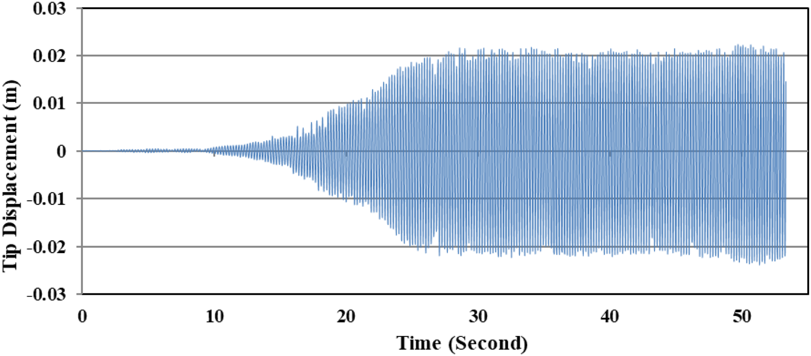
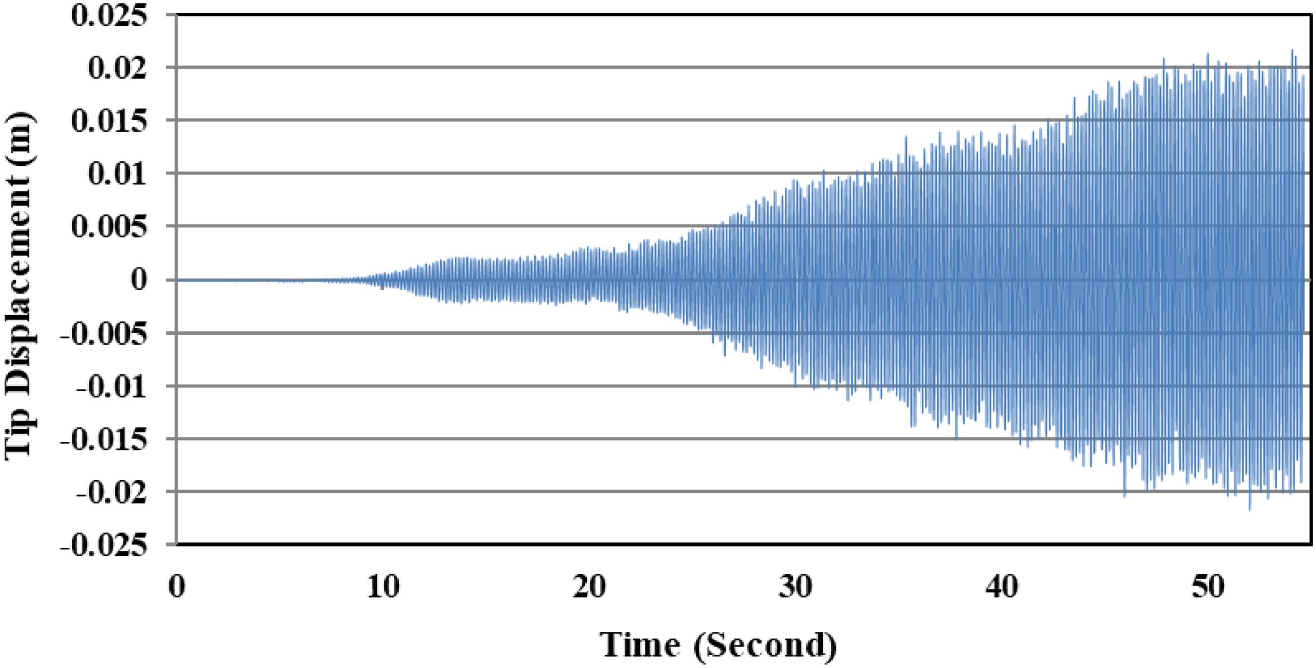
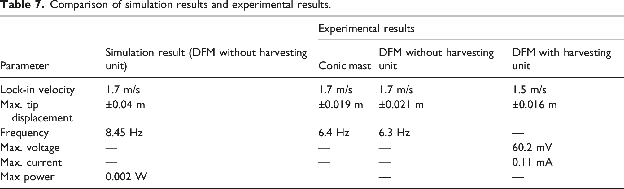
Figure 14 presents a comparison between simulated and experimental tip displacement of the DFM BWT at a wind velocity of 1.7 m/s, corresponding to the lock-in condition. The simulation results exhibit oscillation amplitudes reaching nearly ±0.04 m, while the experimental measurements show peak deflection around ±0.021 m, approximately 50% of the simulated values. Figure 14 depicts the phase lag along with the amplitude attenuation in the experiment compared to the simulation result. The summary of the simulated results and experimental results are highlighted in Table 7. A difference between the simulation and experimental displacement is visible due to experimental errors and unmodeled dynamics. These include wall effects in the wind tunnel, slight variations in the material properties, and the complex interaction between air and the flexible beam, which were not fully accounted for in the simulation. Experimental uncertainties also contribute to this deviation. Comparison of the simulation and experimental results of the DFM BWT at lock in wind velocity, 1.7 m/s. Comparison of simulation results and experimental results.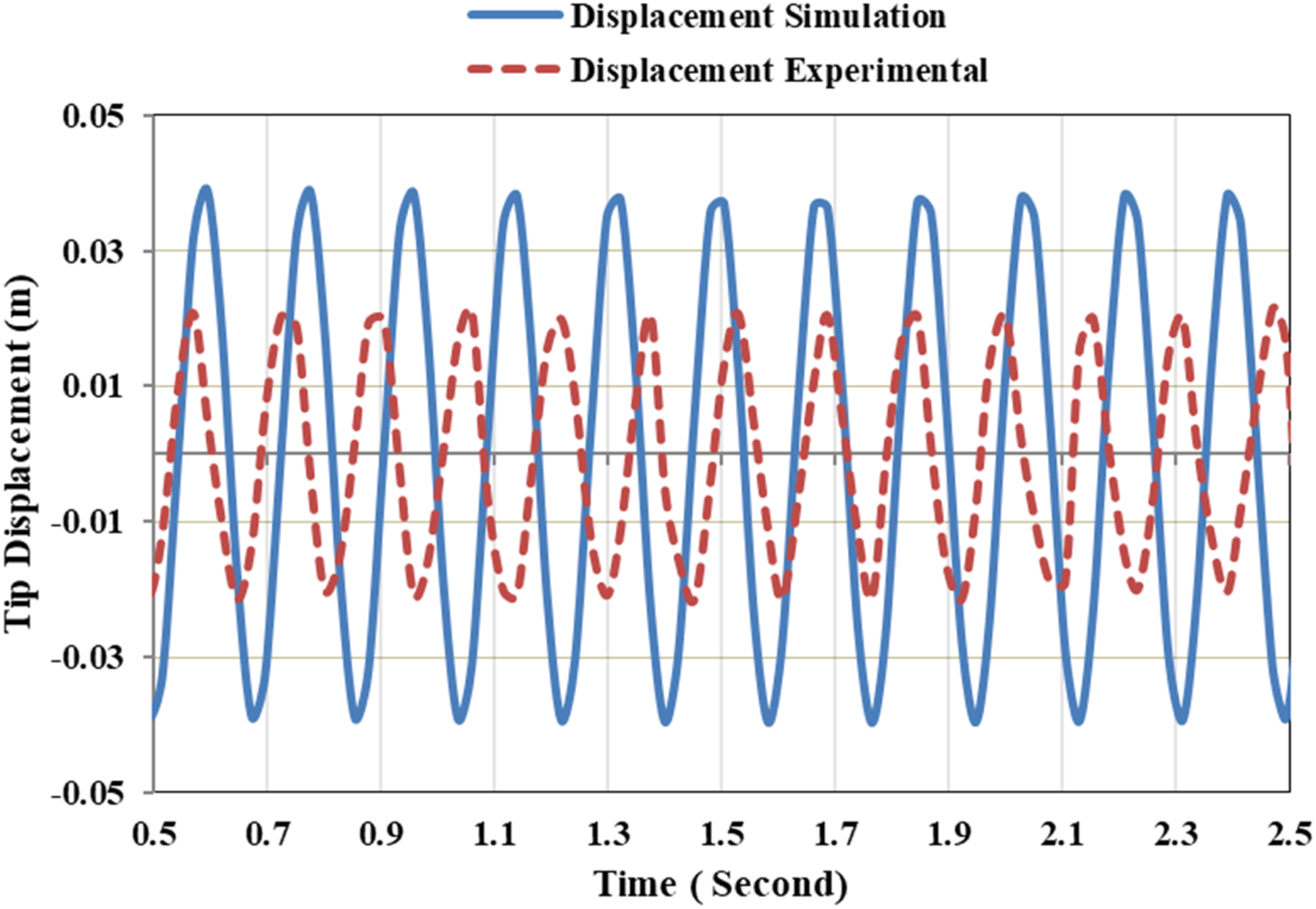
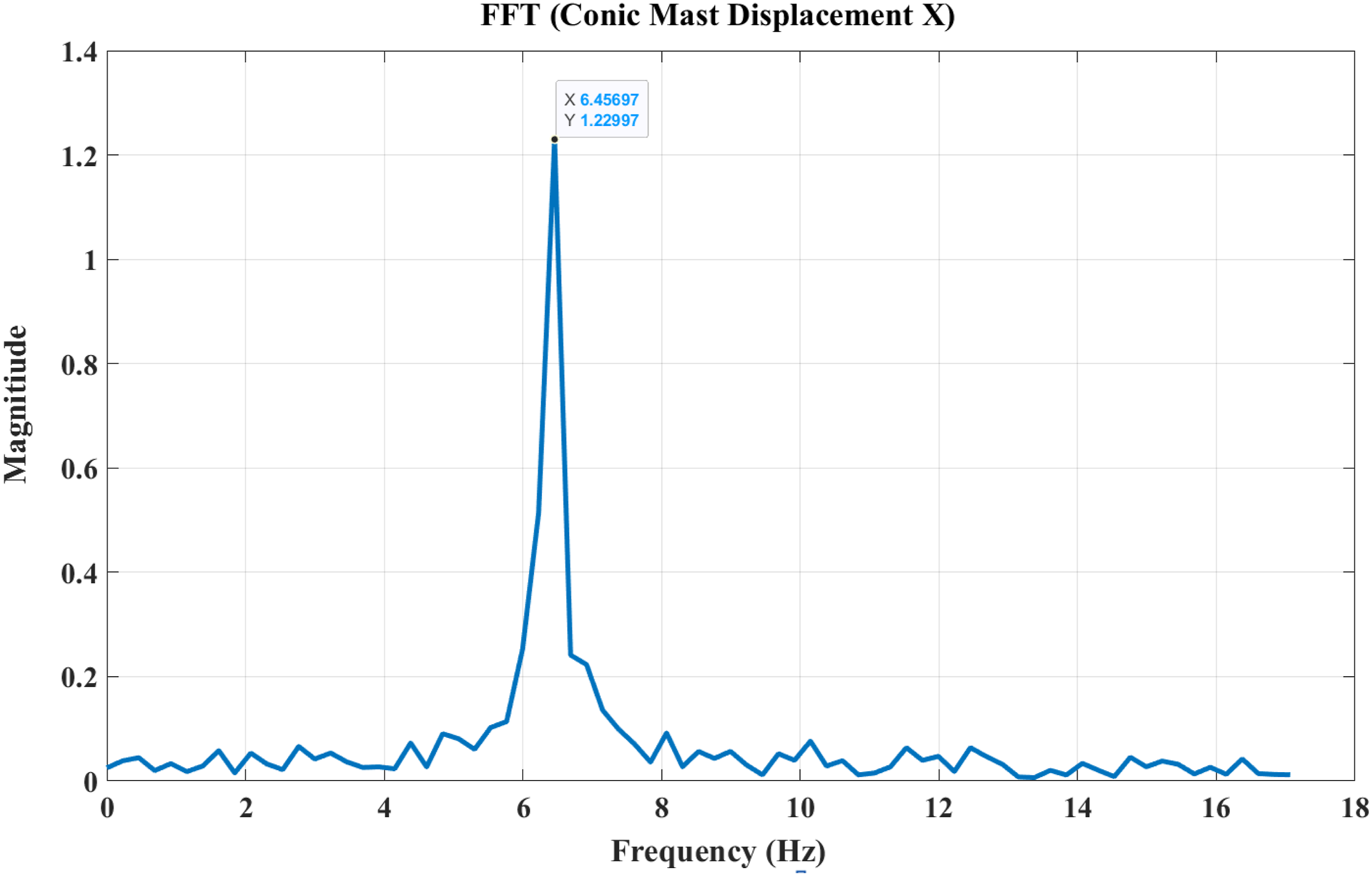
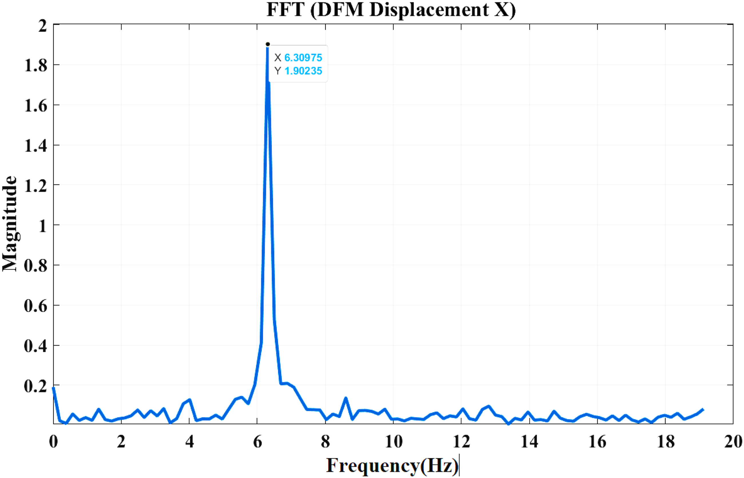
Further, Figure 15 illustrates the time history of the tip deflection for the DFM-BWT (blue line) and the conic mast DFM-BWT (red dashed line) under vortex-induced vibration at lock-in wind velocity. The double frustum mast exhibits a consistently higher average peak deflection of approximately 0.021 m compared to 0.019 m for the conic mast with non-uniform amplitude. This increase in deflection amplitude indicates that the DFM-BWT mast geometry more effectively harnesses aerodynamic force, resulting in stronger oscillations. Moreover, the deflection pattern of the DFM-BWT is notably more uniform and regular throughout the observed period, which can be suggested as a suitable, stable, and predictive vibration. In contrast, the conic mast shows slightly more variability in oscillation amplitude, which could lead to less consistent energy harvesting performance. The enhanced and stable oscillatory behavior of the DFM-BWT design can be attributed to its optimized geometric profile, which likely improves vortex shedding synchronization and structural resonance. Furthermore, Figures 16 and 17 showed the FFT analysis of the conic mast BWT and DFM-BWT, respectively, which show the energy concentration. However, the frequency range of both masts is similar, but a higher magnitude can be observed in the DFM-BWT. The DFM-BWT provides better tip deflection magnitude due to its unique design of the mast. These results underscore the importance of geometric optimization in bladeless wind turbine design, with the double frustum mast demonstrating superior potential for maximizing power output and performance reliability. Comparison between the tip deflection of DFM BWT and conic mast BWT at lock-in velocity. FFT of the tip displacement of conic BWT with experimental data. FFT of the tip displacement of DFM BWT with experimental data.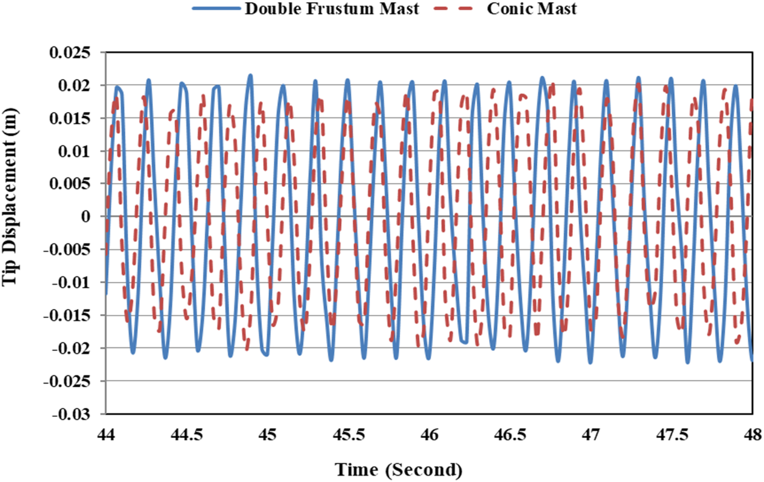
The power output versus wind velocity further substantiates these findings, showing that the double frustum mast consistently outperforms the conic mast across the entire range. The findings underscore the critical importance of geometric optimization in bladeless wind turbine design. Aligning the vortex shedding frequency with the natural frequency of the mast maximizes oscillation amplitude and power output. The double frustum mast, with its enhanced and stable deflection characteristics, demonstrates significant potential for improving the efficiency and reliability of a bladeless wind energy system. These insights provide a valuable foundation for future design improvements and the broader adoption of BWT technology in sustainable energy applications. The comparison of the power output of both mast is shown in Figure 18 Both masts exhibit an increasing trend in power output as the wind speed increases from 0.6 m/s to 1.7 m/s, which highlights the critical influence of resonance phenomena on energy harvesting. The DFM-BWT consistently outperforms the conical mast BWT across the entire wind velocity range, producing higher power output values reaching approximately 0.0095 W at a velocity range of 1.7 m/s compared to about 0.0071 W for conical mast. Comparison of the power output by the DFM BWT and conic BWT at lock in range.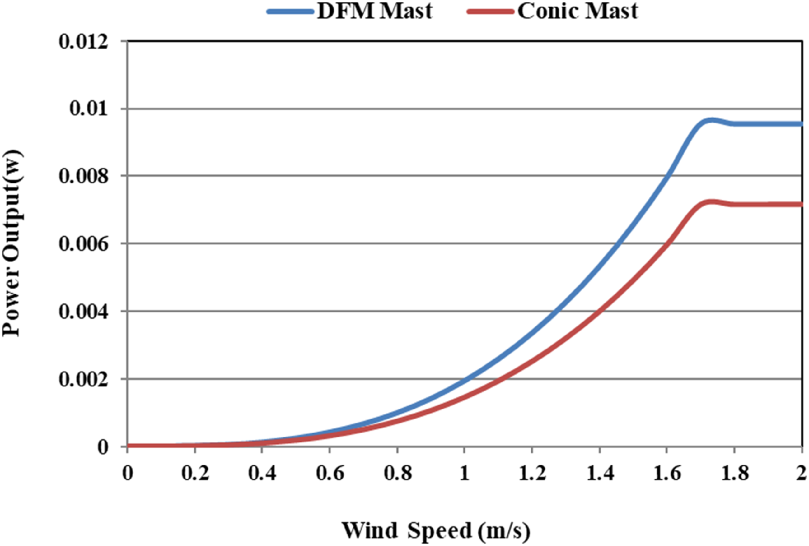
The uncertainties of the experiments are calculated using the sequential perturbation technique (Moffat, 1982; Kline, 1985) and it is found to be 4.4%, 1.7%, and 4.6% for the tip displacement, wind velocity, and power output, respectively.
Figure 19 shows acceleration data from a DFM-BWT experiment with measurements along both x and y axes (refer to Figure 8 for x and y axes) under varying wind speed conditions. Initially, both acceleration along the x and y axes are shown as minimal acceleration, indicating the turbine is in a stationary or near-stationary state, which represents a baseline under low wind velocity. As the velocity of wind increases, the acceleration of the turbine increases with a value starting to fluctuate. Around the 20-s mark, the x-axis acceleration develops into strong, regular oscillations between approximately +15 m/s2 and −15 m/s2. These symmetric oscillations indicate the turbine entering the lock-in regime (Figure 20). Acceleration of DFM BWT along x-axis (blue line) and along y-axis (red line). Tip displacement of DFM BWT with a permanent magnet attached to the beam.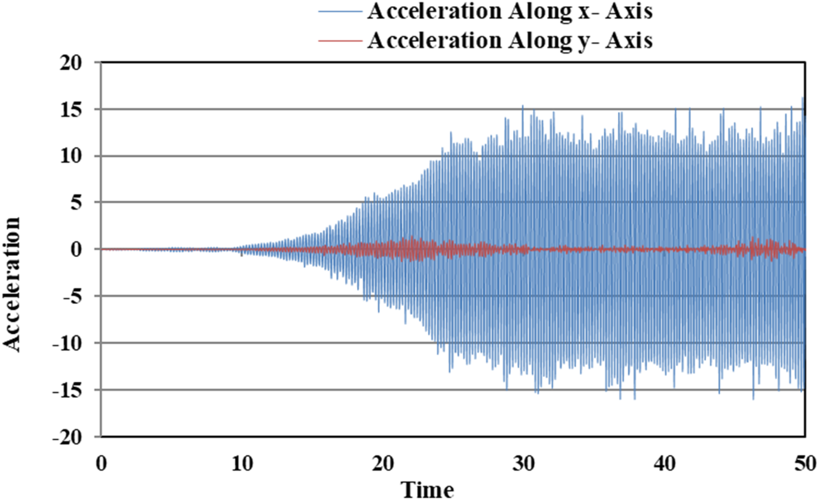
Effect of DFM attached to the harvesting unit
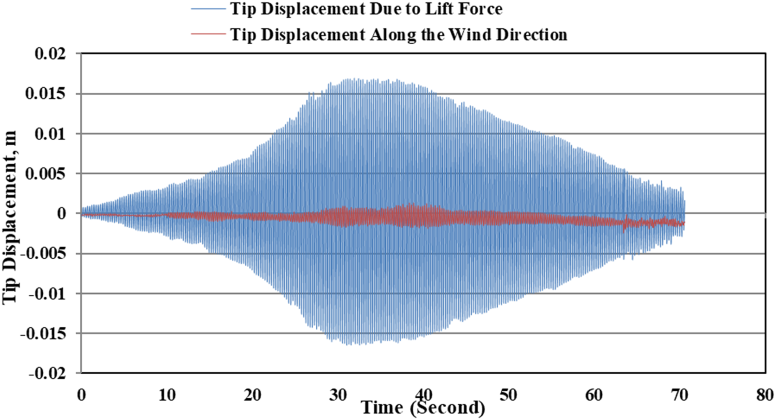
The response of DFM BWT due to attachment of the permanent magnet to the beam at 115 mm distance with reference from the tip of the beam and wind velocity range is 1.5 m/s to 2.2 m/s is considered, which is shown in Figure 18. It is observed that varying the magnet position from the tip varies the oscillation, the mass of the magnet place along the beam acts as a tunable mass which cause of damping effect and the maximum tip displacement is found to be 0.016 m at wind velocity of 1.5 m/s which is comparatively lower than the response of DFM-BWT without magnet attached to the beam. The decoupling phenomenon was also observed, as the wind velocity gradually increases, the oscillation of the beam also starts decreasing, and the mast completely stops oscillating at the wind speed of 2.2 m/s.
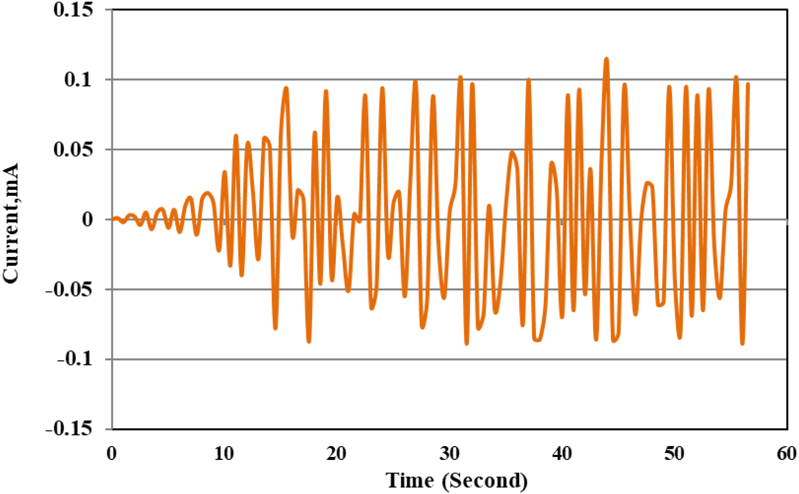
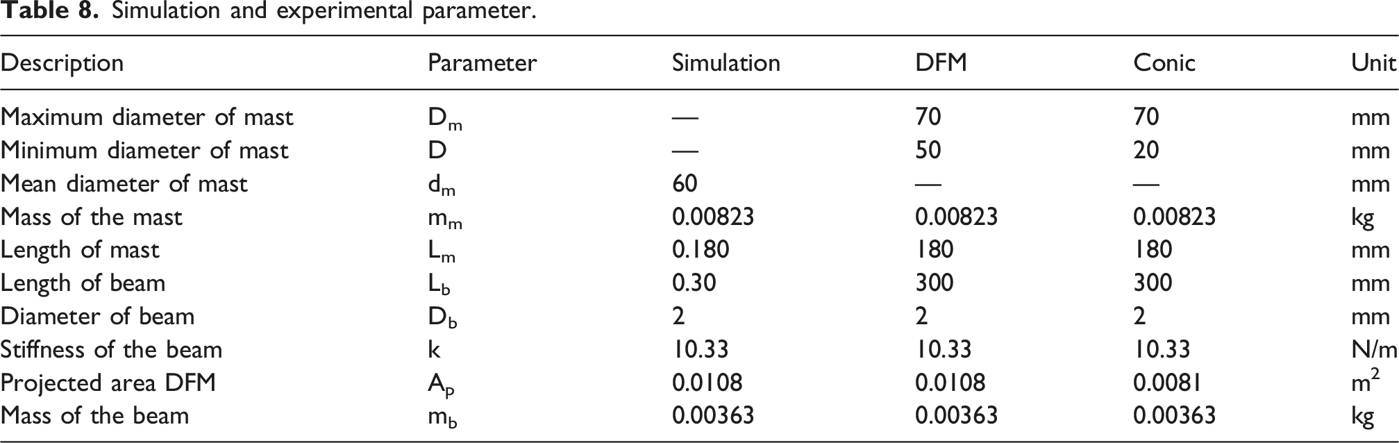
Figures 21 and 22 illustrate the output voltage and current, respectively, generated by the DFM BWT in relation to the tip displacement observed in Figure 18 under a wind speed of 1.5 m/s. The data reveal that the output voltage reaches a peak value of 60.2 mV when the displacement is at its maximum. Similarly, the output current exhibits a spike, attaining a maximum of 0.11 mA at this displacement range. Table 8 shows the comparison of DFM BWT with and without a harvesting unit. Output voltage of DFM BWT at velocity (1.5 m/s). Output current of DFM BWT at velocity (1.5 m/s). Simulation and experimental parameter.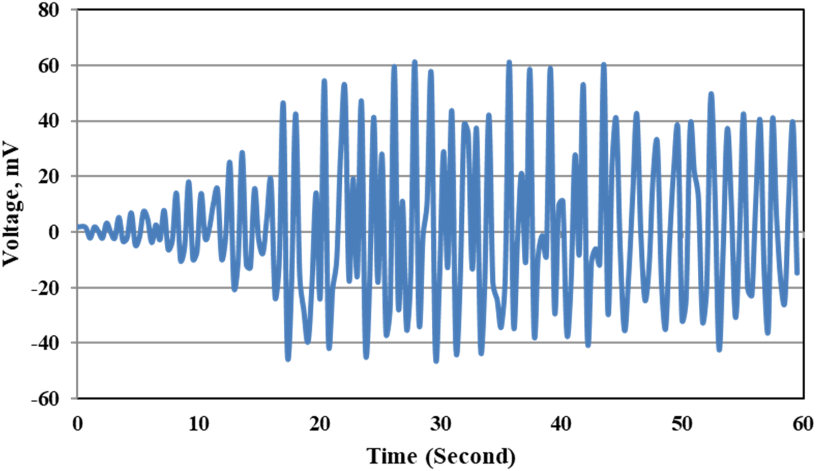
Conclusions and future scope
This study evaluated the performance of a bladeless wind turbine with conic and double frustum mast geometries, using a wind tunnel experiment and numerical simulation using MATLAB Simulink. The results confirm that mast geometry is critical for optimizing energy harvesting via vortex-induced vibration (VIV). Experimental and simulation data reveal that the DFM-BWT achieves higher, stable, and more uniform tip deflection (0.021 m), demonstrating significant potential for improving the efficiency and reliability of BWT as compared to the conic mast (0.019 m) at the Lock-in Velocity of 1.7 m/s. Power output data further validates these findings. The DFM-BWT generated 0.037 W consistently, outperforming the conic mast at 0.03 W across the tested wind velocity range. Hence, the DFM-BWT shows an improvement of 23.33% higher power output over the conic mast.
Experimentally, the DFM-BWT with a permanent magnet attached 115 mm from the tip of the beam achieved a maximum tip displacement of 0.016 m at a wind velocity of 1.5 m/s. Varying the magnet position altered oscillation amplitude, resulting in approximately 24% lower displacement compared to the unweighted (no magnet) configuration. This reduction caused by adding mass is a noticeable limitation, but it can be mitigated by implementing a tunable mass system. Adjusting the magnet’s mass or position with wind speed can function as a variable mass damper, extending the effective operating range.
The corresponding peak output voltage was 60.2 mV, and a decoupling phenomenon was also observed as wind speed increased, beam oscillation decreased, ceasing entirely at 2.2 m/s. While decoupling limits power generation, it may prevent structural failure during turbulent weather. Future work should prioritize optimizing this tuning mechanism and rigorously investigating the decoupling threshold. Apart from exploring different shapes of mast, the materials for the BWT also need to be studied.
Further work is needed to better understand the airflow behavior and patterns around the mast. A detailed investigation of the fluid-structure interaction (FSI) for the developed BWT mast will be conducted to clarify the underlying flow physics, aerodynamic performance, and key parameters. Additionally, 3D unsteady simulations of the new mass geometry will be performed using the multi-physics solver ANSYS Fluent, employing an appropriate turbulence model to resolve the flow physics. Although vortex generators’ effects on aerodynamic performance have been widely studied, no research has yet examined the influence of their shape and material. These insights provide a foundation for future design improvement and the broader adoption of bladeless wind turbine technology in sustainable energy applications.
Footnotes

Author contributions
The first author, Mr. Allan Lamb War, carried out the work and wrote the original manuscript. However, Dr. Nur Alom and Dr. Bikash Kumar Sarkar conceptualized, supervised the work, and edited and corrected the manuscript.
Funding
The authors received no financial support for the research, authorship, and/or publication of this article.
Declaration of conflicting interests
The authors declared the following potential conflicts of interest with respect to the research, authorship, and/or publication of this article: We hereby declare that there are no financial or personal relationships with any individuals or organizations that could have influenced this work. The work reported forms part of the master’s thesis carried out by Allan Lamb War, a master’s student at NIT Meghalaya.
Data Availability Statement
The datasets used in this study can be obtained from the corresponding author upon a reasonable request. Relevant supporting data are also accessible in the publicly available literature.