
Abstract
With the effort to precisely predict the lifetime of asphalt binders and subsequently optimize their utilization in a more economical way, the objective of this study was to introduce a new methodology to improve the fatigue characterization of asphalt binders through a new dynamic shear rheometer (DSR) sample testing geometry. Initially, numerical analyses were performed to study the geometry-related issues of a standard DSR sample on time sweep tests, and to assist in the effort to increase understanding of the DSR damage phenomena of asphalt samples. On the basis of these numerical analyses, a new testing geometry, the parallel hollow plate, was developed and its test results compared with the standard sample testing geometry. A single type of asphalt binder was assessed using amplitude sweep tests. The obtained results demonstrated a significant difference between the fatigue of the two sets of DSR sample geometries. On the basis of these, time sweep tests were conducted for the same sample geometries and the results demonstrated that the new testing geometry yields material response consistency under different loading conditions. The lifetime prediction of the standard parallel plates showed a significant difference with the newly developed DSR sample testing geometry by overestimating the total number of cycles until asphalt binder failure. The new testing geometry allowed the isolation of the damaged area of asphalt binder by localizing the shear stresses in the samples’ periphery.
Owing to the extremely complex nature of asphalt binders, it is difficult for infrastructure designers to accurately predict the lifetime of the pavement structures. Taking into account the higher and heavier traffic on the highways in the last decades, implementation of new asphalt binders for the highway network has increased remarkably resulting in higher initial costs for pavement construction. Furthermore, difficulties have been identified in estimating serviceability and planning maintenance operations during the pavements’ service life. Various parameters affect the performance prediction of asphalt binders and instead of making progress in the testing techniques, the challenge of precisely characterizing binder fatigue life still needs to be addressed.
Fatigue damage as one of the main asphalt binders’ distress modes can be described as the material degradation process because of repeated loading by which the micro-cracks grow and the coalescence to macro-cracks. Typically, fatigue in asphalt mixes is studied by subjecting the test material to some form of cyclic stresses at a lower level than the ultimate strength and then determining the relative change in their mechanical properties, such as stiffness and strength. Therefore, having a test method that can predict the mechanical degradation of material, will allow comprehension of the exact damage mechanisms in detail and subsequently to optimize the utilization of asphalt binders in a more feasible way.
However, asphalt binder fatigue characterization is not uncharted territory for the paving industry. Several laboratory studies have been conducted to provide understanding of the degradation mechanism due to repeated stresses, and ranking of the binders’ susceptibility to resist these stresses. Unfortunately, the results from the tests do not precisely predict the field performance of asphalt mixes. As a result, the need to improve testing methods for the quality control of asphalt binders to ensure accurate lifetime estimations has been increasing. The dynamic shear rheometer (DSR) has been introduced for use in fatigue characterization of binders ( 1 – 3 ). However, a satisfactory link between the measured binder fatigue response using DSR and the potential field material performance over a range of various operational conditions is still under investigation.
Within this framework, a study has been initiated to evaluate a potentially more appropriate DSR fatigue-testing method. The new parallel hollow plate (PHP) system was designed and developed with an outer diameter of 25 mm, as with the standard geometry of DSR parallel plates (PP), but with a concentric hollow area of 19 mm diameter and 0.1 mm depth. After filling the inner hollow area with a silicon paper, the new testing system was used to explore the impact of the mechanical performance of asphalt binders. For the selected new geometry system, after carrying out assessment of the repeatability of the test results, different dynamic shear measurements were conducted to evaluate the material’s response. The experimental results demonstrated the significant variations on binder performance at low and high cyclic torque level tests between the new and the standard DSR apparatus. This comparison underlines the significance of geometry for DSR plates for a more accurate material characterization, and the upcoming need to minimize the geometry-related issues by localizing the shear damage in the tested material.
Fatigue in Asphalt Binder
Fatigue damage in asphalt is the degradation of the material due to repeated loading by which the cracks grow and the material loses its capability to resist more loads. Significant effort has been spent on evaluating asphaltic materials’ fatigue life and thus several methods have been developed through this process. These methods differ mainly in terms of the fatigue damage approaches and testing configurations, such as the sample’s geometry, loading conditions, and so forth. Here, emphasis is given to assessing the fatigue performance of asphalt binders and, for this reason, state-of-the-art DSR utilization as a fatigue characterization tool is discussed.
Fatigue Damage Approaches
The fatigue life of asphalt binders has been thoroughly examined, and several approaches such as energy-related, mechanistic, and phenomenological approaches have been utilized to evaluate the material’s response under cyclic load repetitions and to determine the remaining life of the material.
Among energy-related approaches, the energy ratio as a function of the number of cycles and the complex shear modulus for the different controlled modes has been applied as a fatigue life criterion ( 4 ). In the stress-controlled mode particularly, the fatigue life of the material is defined as the point when the energy ratio reaches its peak in the relationship of energy ratio versus the number of cycles. On the other hand, in the strain-controlled mode, the fatigue life is defined as the number of load cycles at which the slope of the energy ratio deviates from a straight line.
Another energy approach is the dissipated energy ratio, which is defined as the ratio of the difference between the dissipated energy for the successive load cycles to the dissipated energy of the previous cycles ( 5 , 6 ). The dissipated energy ratio is the area inside the hysteric loop ( 7 , 8 ), and the fatigue life of the material is considered as the transition point where the dissipated energy ratio starts to increase rapidly from an approximately constant value ( 6 ). Similarly, the dissipated strain energy approach has been used by converting the actual strain to an equivalent pseudo-strain in order to remove the viscoelastic contribution ( 2 , 9 ), and to quantify the damage manifestation using mechanistic approaches such as continuum damage and fracture mechanics ( 10 – 12 ).
Finally, phenomenological approaches are the most frequently used to define fatigue life. One example of such an approach is the determination of fatigue as the number of cycles when the complex modulus decreases to 10% and 50% of the initial complex modulus for stress- and strain-controlled testing modes, respectively ( 13 , 14 ). However, the failure criterion of 50% complex modulus reduction is irrelevant to the damage accumulation as this value is arbitrary and varies at different loading modes. Others consider the fatigue life of asphalt as the point at which the stress level changes rapidly ( 15 ), however this approach is sensitive to the test loading conditions. In this study, the total number of fatigue cycles until complete failure of the sample or the end of test is used as the fatigue life criterion ( 16 ).
DSR Fatigue Damage Characterization
DSR is commonly used as standard performance testing equipment to characterize the viscoelastic properties of asphalt binders ( 17 – 19 ). Additionally, to evaluate the fatigue damage mechanism and to predict the fatigue life in asphalt binders, DSR has been utilized using the oscillatory time sweep (TS) test ( 1 – 3 ). Previous researchers have demonstrated that damage initiates at the outer periphery of the material and propagates through the sample with increasing numbers of loading cycles. Thus, damage results in a reduction of the radius of the test sample. Specialized imaging techniques have been used to demonstrate fatigue damage during DSR testing and the obtained images clearly demonstrate non-uniform damage with fractures at the outer edge of the testing plates and an intact center ( 2 , 3 , 20 ).
Others who studied the phenomena of fatigue with DSR have shown damage propagation as hairline cracks propagating toward the center accompanied by modulus decrease ( 21 ). The fatigue damage mechanism does not include internal damage because the edge fracture is dominant, especially in oscillatory TS tests ( 5 ). However, these are not the only issues that are encountered with the standard DSR test methods using a PP: the accuracy of the complex modulus is limited since the generated radial stress field is nonlinear. Many aspects of DSR fatigue characterization are elaborated with approximations and extrapolations analogous to how Ptolemy used epicycles to explain the planets’ movements around the earth. The urgency to improve fatigue-testing methods and the asphalt binders’ quality lies in the need to resolve the inaccurate use and interpretation of DSR and to link the DSR-measured response of binders with field pavement performance. In the following section, numerical analyses are presented that study the geometry-related effects of DSR sample testing on fatigue damage. Furthermore, the numerical simulations of fatigue damage will assist in the effort to increase understanding of the damage phenomena of asphalt samples during DSR TS tests and to further optimize the testing configurations for obtaining more realistic material properties.
Numerical Simulation of DSR Fatigue Damage
Model Parameters Determination
A damage model was developed to illustrate the damage distribution of asphalt binder during a DSR TS test. The material parameters that were required as an input were modeled based on a linear viscoelastic response. The complex modulus values of asphalt binder were determined from frequency sweep tests in the standard PP DSR system. These tests were carried out over a temperature and frequency range from −10°C to 60°C and from 0.1 to 100 Hz, respectively. Instrument compliance was measured and accounted for in these measurements. The asphalt binder used was a commonly applied binder for porous asphalt mixes in Dutch roads, the penetration grade 70/100 unmodified bitumen. By employing the frequency-temperature superposition principle, the master curve in the frequency domain was defined (reference temperature of 20°C).
Continuum Damage Model
After determining the material parameters, with the Prony series coefficients (G∞, Gi and ρ i ) obtained by fitting the experimental data with the storage modulus, the relaxation modulus could be expressed in the time domain as follows:

where
G(t) is the shear relaxation modulus in time domain,
t is the loading time,
G∞ is the long-time equilibrium modulus,
Gi are the spring constants in the generalized Maxwell model,
ρ i are the relaxation times, and
n is the number of Maxwell components in the generalized model.
If it is assumed that the Poisson’s ratio of binder is time independent and that the material is isotropic, the following expression that relates the G(t) to E(t) can be written as

where E(t) is the relaxation modulus and
In continuum mechanics, the damage is defined as a function of any micro-mechanical change that develops in a homogeneous continuum media. To include damage in the above-described material model, the following damage evolution equation was proposed based on total dissipated energy as

where
t is time,
W is the total dissipated energy, and
k and r are damage rate parameters.
In incremental form Equation 4 can be written as
where
The total energy dissipation W can be computed in incremental form as

where
i is the index of the Maxwell component,
n is the number of Maxwell components,
Using the midpoint integration rule Equation 5 can be simplified to
Numerical Implementation
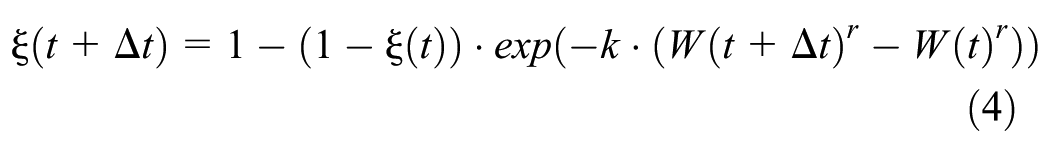
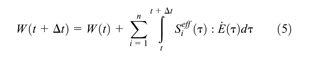
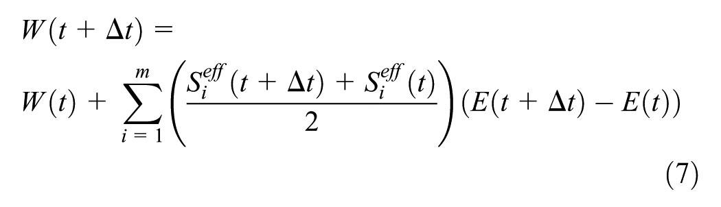
The CAPA 3D system was utilized. Three user-defined 3D finite-element (FE) meshes were created to study the damage distribution and the localization of asphalt sample deterioration in a sinusoidal (oscillating) loading mode during a TS DSR test (Figure 1). The first FE mesh representing the standard DSR geometry of 2,400 cubic finite elements was developed. This DSR geometry comprises the two PPs in which the asphalt binder is located in-between, with the top plate being subjected to torsion and the bottom plate being fixed. Similarly, the second FE mesh of DSR geometry with a ring as the top plate and an inner and outer diameter of 19 mm and 25 mm, respectively, was created of 2,200 finite elements. This configuration was called a one ring-type testing system. A third mesh, a two rings-type testing geometry, comprising two rings instead of solid plates of 2,000 finite elements was generated.
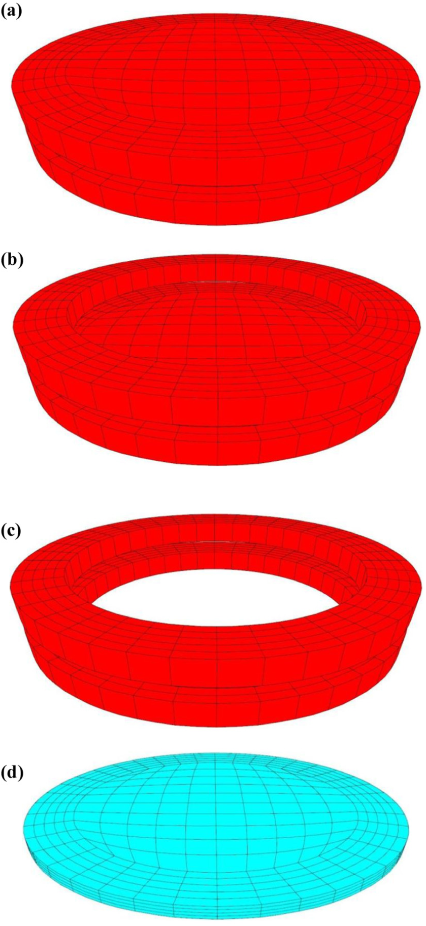
Three-dimensional meshes of (a) standard plate-type, (b) one ring-type, (c) two rings-type DSR sample testing geometries, and (d) the testing sample.
To assess the fatigue damage behavior under the same applied torque (0.245 Nm), the load level was converted to shear stress (τ) based on the testing geometries. According to the elastic torsional theory, the shear stress (

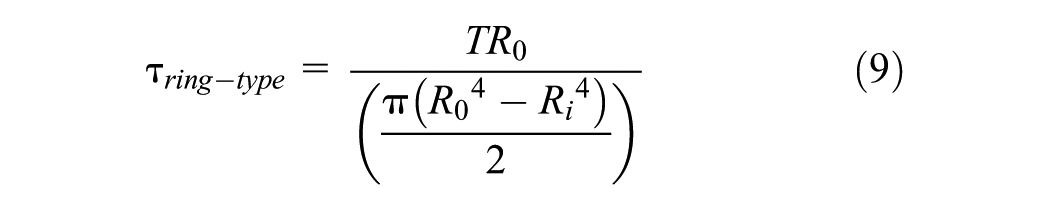
where
T is torque,
R0 is the outer radius, and
Ri is the inner radius of the plate.
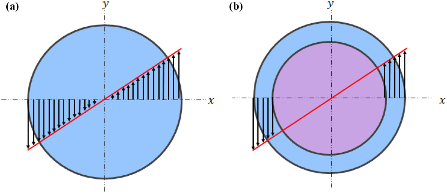
Shear stress distribution on (a) standard plate-type, and (b) one ring-type sample geometry.
Numerical Predictions
In Figure 3, the damage distribution within the specimen was obtained after subjecting the standard plate-type model to a torque of 0.245 Nm at 10 Hz frequency. The results from this analysis demonstrate that the material degradation during a PP DSR TS test differs across the sample’s radius. Specifically, the top part of Figure 3 visualizes the damage progress over time for the first six TS cycles. With increased loading, it is apparent that the damage, as reflected by the different colors in the figure, is concentrated in the outer periphery. Plotting the damage values versus time gives the bottom graph in Figure 3, where the damage increases more rapidly in the points closer to the sample’s periphery. As can be observed, the damage of the inner area of binder is not the same as the edge or at locations close to the edge. The damage rate shows the inner part of the testing binder is not affected significantly by the torsional-induced damage of the plates. Therefore, these results corroborate the previously mentioned mechanism of damage initiation at the outer periphery of the sample and the almost intact center during a DSR fatigue test ( 5 ).
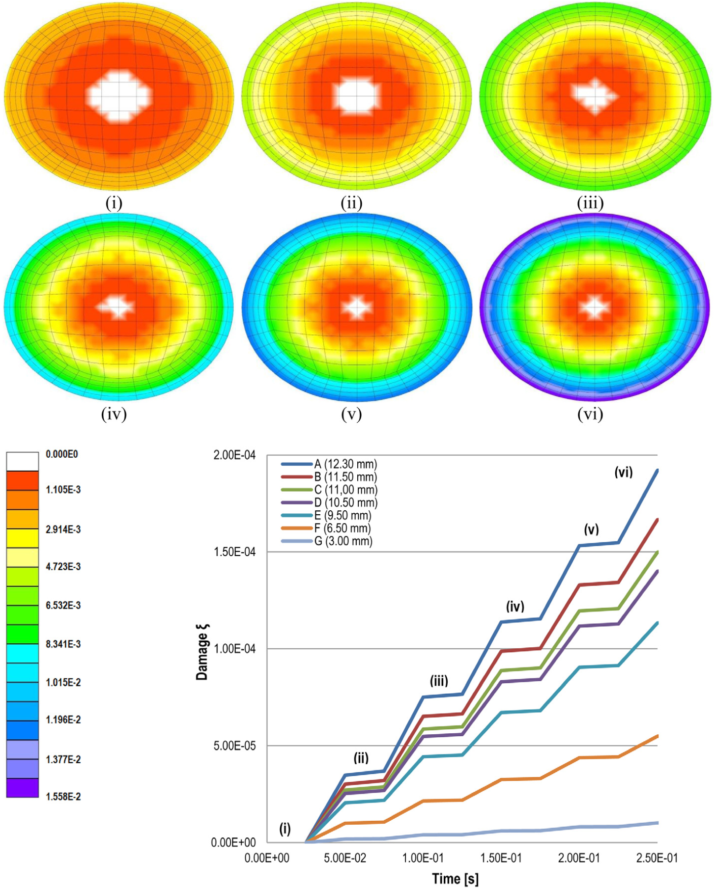
Predicted development of damage along the radius of the standard DSR sample testing geometry.
Figure 4 compares the performance of the standard DSR geometric configuration and of the two ring-type geometries. The new geometries show a higher magnitude of damage localized on the ring area than the plate-type sample geometry for a given number of loading cycles (bottom of Figure 4). This difference is explained by the way the area that resists the applied torque is limited in the ring-type geometry compared with the standard system. Additionally, the impact of the top rotating part on the shear stress field and the subsequent damage propagation generated by the applied torque across the sample’s radius is shown in Figure 5. For the ring-type geometries, the stress flow field appeared only on the outer periphery of the sample with very limited inward stress propagation for the one ring-type and two rings-type sample geometries, respectively. The edge damage phenomenon to the ring-type geometry occurs earlier than the plate-type sample geometry on account of the higher stress magnitude.
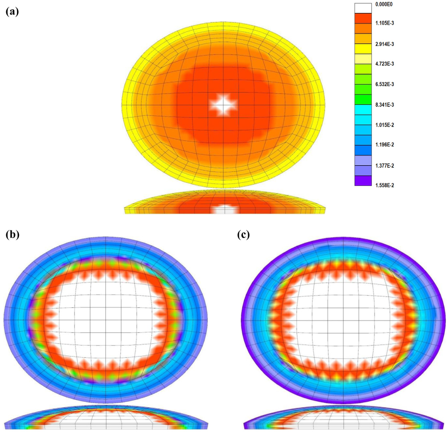
Simulation of damage distribution of: (a) standard plate-type, (b) one ring-type and (c) two rings-type DSR sample testing geometries at the end of the analyses.
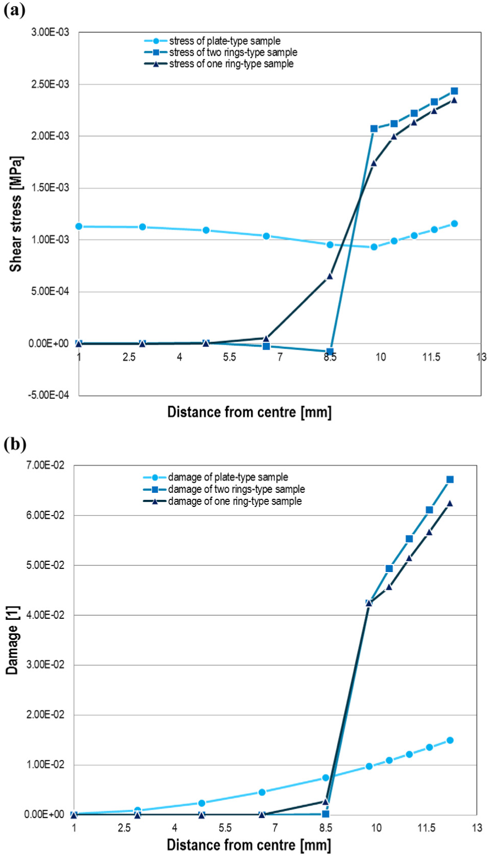
Predicted (a) stress and (b) damage distribution over the sample’s radius of different DSR sample testing geometries at the end of the analyses.
Additionally, the stress and damage difference across the sample’s thickness at three different points at a certain time period is demonstrated in Figure 6. It is obvious that the standard geometry shows significant variation in damage across the sample’s thickness at all these points. The one ring-type geometry has a bit less damage at the same location than the two rings-type testing configuration. All these predicted results reinforce recent studies on the lack of accuracy of the standard DSR sample testing geometry and the limitations of this system on providing true material properties ( 22 – 25 ).
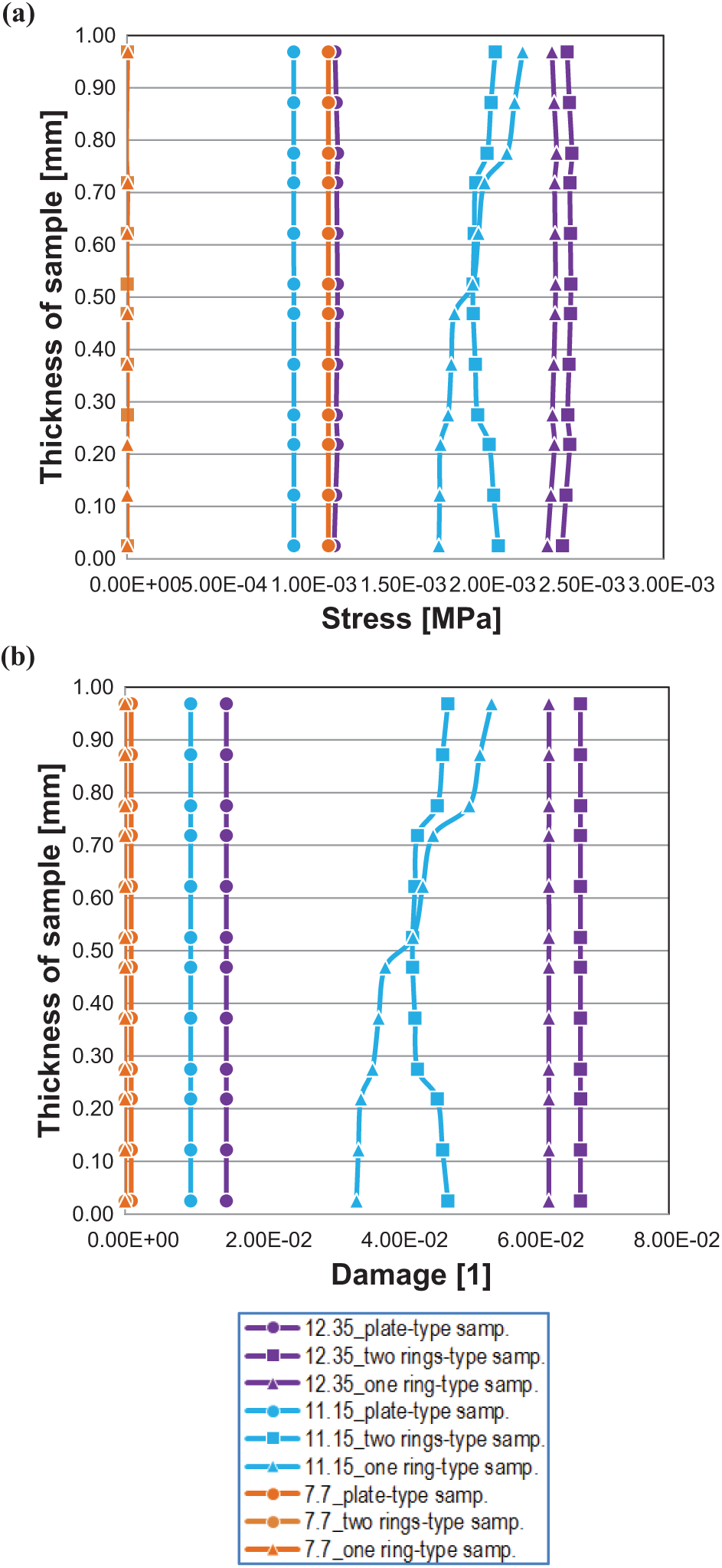
Predicted stress and damage distribution over the sample’s height at different points over the sample’s radius of the DSR sample testing geometries at the end of the analyses.
Improving DSR Fatigue Damage Characterization
On the basis of the evidence from past research and the predicted results from implementing the previously described continuum damage model, the main objective of this part of the study was to introduce a new methodology to accurately characterize the fatigue performance of asphalt binders through a new DSR testing system. Different dynamic shear measurements were performed to assess the material response by using the standard PP and the newly developed PHP configuration. The ability of the new geometry to characterize asphalt binder fatigue was also evaluated.
Test Methods
The standard DSR sample geometry is the PP with smooth polished surfaces and a typical diameter of 25 mm. A new sample testing geometry was designed and manufactured on the basis of the previous numerical analyses. Similar to the one ring-type geometry, the new PHP sample geometry has an outer diameter of 25 mm with a concentric hollow space of 19 mm diameter and 0.1 mm depth. The testing procedure is shown in Figure 7. The DSR setup was utilized for testing with the conventional PP and the new PHP, both with a 1 mm gap in accordance with the Superpave specifications, and obtaining the material response. After filling the inner hollow space of the PHP with a silicon paper, the new testing system was used to explore the impact of the mechanical performance of asphalt binder. A zero gap between the upper and lower plates was established and after reaching it, a 1 mm gap was set by moving the plates apart.
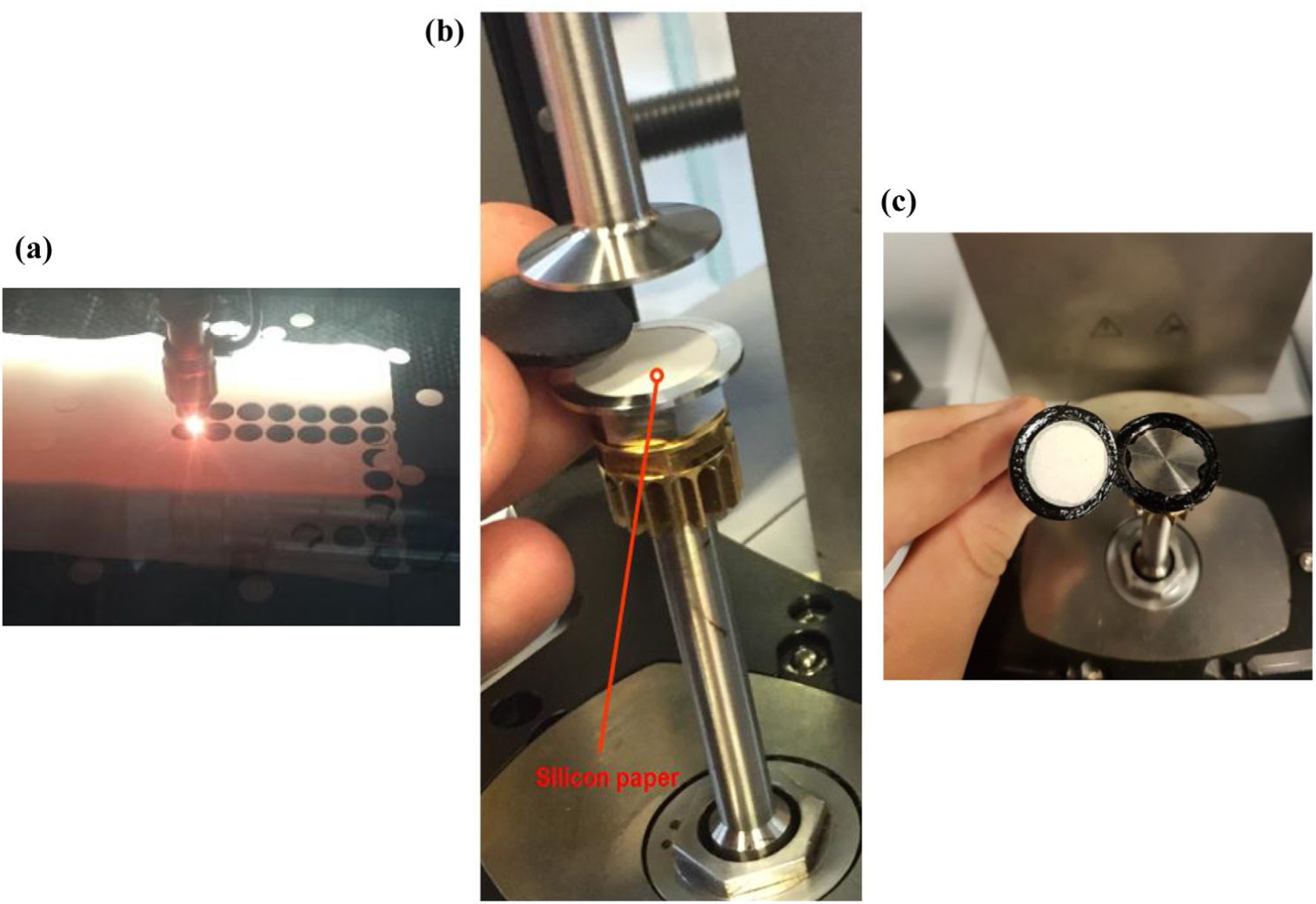
PHP DSR sample testing system: (a) laser cutting of silicon paper, (b) sample placed on the PHP DSR plates, and (c) view of top plate after test completion.
Amplitude Sweep Measurements
To obtain a dynamic material response for a very short loading time, a varying torque signal is applied with a fixed sinusoidal oscillatory frequency. In this study, a cyclic strain-controlled torque was applied throughout the test causing a constant rotational strain. These DSR experiments resulted in amplitude sweep results for the two different sample geometries at 35oC for further comparison. Furthermore, these results were used to determine the linear viscoelastic range and a level of applied torque of 10 Hz frequency for conducting the TS studies in the latter step.
Time Sweep Measurements
The material damage manifests as a decrease in the complex modulus and an increase in the phase angle in the asphalt binder. In this study, the damage was quantified as the reduction in the complex modulus measured during the cyclic loading test with DSR. The TS torque-controlled loading mode was used to evaluate the binder fatigue life and the performance difference between the two sample testing geometries. During these tests, the samples were subjected to a sinusoidal loading mode with a fixed frequency of 10 Hz at 35°C.
Test Results
Amplitude Sweep Results
For the selected geometries, after assessing the repeatability of the test results, different dynamic shear measurements were conducted to evaluate the material response using an amplitude sweep test. Figure 8 depicts the variation in viscoelastic properties versus applied torque at 10 Hz frequency and 35°C. The effect of the new testing geometry is also demonstrated. The torque amplitude was increased in small amounts instead of large steps in each cycle. From the data, it can be observed that the complex modulus dropped and the phase angle increased first when the material was tested using the PHP configuration. The limited area in the outer periphery of the PHP caused quicker degradation than the PP system when the torque was increased. Thus, it is obvious that the material degradation rate is a function of the damaged area for an amplitude sweep test and subsequently of the testing geometry.
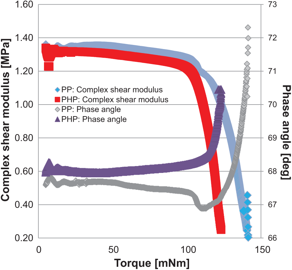
Amplitude sweep results. Rheological properties versus torque for the different sample testing geometries.
Time Sweep Results
The fatigue life of asphalt binder is influenced by various factors such as temperature, loading level, and frequency. In this study, the testing was done at 35°C in which the initial complex shear modulus was 0.5 MPa. Very different fatigue performances were observed between PP and PHP geometries. Figure 9 demonstrates the complex shear modulus versus the number of cycles from applying a torque level of 50 mNm. As expected, with increasing numbers of fatigue cycles, the complex modulus of the PHP dropped first as the tested area was limited, indicating the faster occurrence of damage. In addition, the shear modulus reported using the PP geometry is actually an average of the damaged periphery and the intact core.
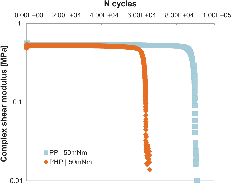
Complex shear modulus versus number of cycles of different sample testing geometries.
Figure 10 shows the fatigue life curves for PP and PHP DSR geometries. Here, the most commonly applied fatigue life criterion is considered to be the number of loading cycles at which the complex shear modulus reaches its lowest value. As failure happened only at the sample’s periphery in the PHP system, PHP appeared to result in a shorter binder fatigue life for different applied torque levels. The propagation of the micro-cracks from the edges to the internal area of the sample using the standard geometry produced more cycles in the TS tests. The TS results of the newly developed sample testing geometry indicate the importance of characterizing fatigue performance accurately. According to these results, the fatigue resistance offered by the PP in a TS test was influenced as an artifact of the geometry. However, in addition to the various models that are utilized to successfully predict the fatigue life of material, precise testing to obtain accurate material properties should be a priority.
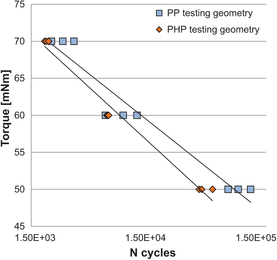
Fatigue life curves of different sample testing geometries.
Summary of Findings and Future Work
From the perspective of pavement design, it is important to be able to predict the fatigue life of an asphalt binder as a result of cyclic loading over time. This study proposed a new testing geometry to more accurately predict the binder’s fatigue life. On the basis of analyses and test results collected in this study, it can be stated that a less geometry-dependent measurement of fatigue damage was achieved using the newly developed DSR configuration, showing the importance of using precise testing systems for accurate material performance predictions.
The damage continuum model that was developed to demonstrate the non-uniform damage distribution of asphalt binder subjected to sinusoidal loads with the standard sample geometry showed that the damage was localized in the sample’s periphery, leaving the center intact. The visualization of the concentration of damage during the fatigue testing with DSR was used as evidence to manufacture a new testing configuration with an inner hollow space in the center of the bottom plate. After conducting TS experiments using PP and PHP configurations, the fatigue life predictions of the two geometries showed a significant difference, with the edge damage phenomenon happening earlier for the PHP than the PP. The very different observed fatigue performances were derived from the way the new sample testing geometry allowed isolation of the material damage by localizing the shear stresses in the sample’s periphery.
Further study is needed to maximize the damage by increasing the diameter of the inner hollow space, and the test loading and environmental conditions should be expanded to provide more realistic fatigue predictions. Moreover, extensive experimental programs are required to be performed to develop transferring functions to convert the results of the new geometry to the results derived from the standard DSR geometry for modified and unmodified binders.
Footnotes
Author Contributions
The authors confirm contribution to the paper as follows: study conception and design: P. Apostolidis, A. Scarpas, A. Bhasin; data collection: P. Apostolidis, C. Kasbergen; analysis and interpretation of results: P. Apostolidis, A. Bhasin, A. Scarpas S. Erkens; draft manuscript preparation: P. Apostolidis. All authors reviewed the results and approved the final version of the manuscript.
The Standing Committee on Asphalt Binders (AFK20) peer-reviewed this paper (18-02473)