
Abstract
Stay cable systems are used extensively for the construction of long-span bridges owing to their inherent advantages. In most cable-stayed bridges the steel strands within the main tension elements (MTEs) are grouted to provide a corrosion protection system. However, there could be segregated grout, voids, and water accumulation/infiltration within these voids in the ducts due to poor quality of the grouting material and grouting techniques. These locations may act as initiators for the corrosion of steel strands within the ducts, which can have serious implications on the load carrying capacity and safety of cable-stayed bridges. In this investigation, several nondestructive evaluation (NDE) techniques are evaluated to determine their ability to detect grout defects within the anchorage regions, end caps, and MTEs of the stay cable system. Four stay cable specimen mock-ups with known grout defects and voids were fabricated. NDE methods that were part of this investigation included ground penetrating radar, infrared thermography, electrical capacitance tomography, impact echo, sounding, ultrasonic tomography, ultrasonic pulse velocity, low frequency ultrasound, visual testing, and borescope. While a few NDE methods could identify voids and water infiltration defects within the high-density polyethylene (HDPE) MTEs, it is evident that there is still a need for a method that is effective in detecting grout defects within the metal ducts embedded in the anchorage region and metal MTEs. Although visual testing and borescope methods are effective in identifying the defects, prior information about the location of the defects is generally required.
Stay cable systems have been widely used for long-span bridges. A cable-stayed bridge consists of a bridge deck supported by a system of inclined cables, or stays, passing over or attached to towers located at the main abutments or piers. The cables typically consist of a group of strands, which in turn are made from a set of wires. Due to economy in weight, material, and cost, as well as its versatile concept that lends itself to a wide variety of geometric configurations, modern cable-stayed bridges have been successfully used in the United States since the late 1970s. Although cable-stayed bridges are not a new development, their application has not been widespread until recently.
Corrosion of strands in cable-stayed bridges is a major problem. Many different protection systems have been used to provide long-term durability and corrosion resistance to the stay cables. However, almost all these methods have experienced problems. In a comprehensive survey of cable-stayed bridges around the world, Watson and Stafford ( 1 ) concluded that nearly 200 cable-stayed bridges are in danger due to potential corrosion problems in stay cables. Several other researchers claimed that Watson and Stafford overstated the problem ( 2 ). Although Watson and Stafford’s conclusions were controversial, it started a necessary dialog on the corrosion of stay cables and the principal cause of cable deterioration.
Various factors such as misalignment of anchorages, excessive vibrations under live load, and excessive use of de-icing salts on the bridge deck contributed to the failure of wires in the Kohlbrand Bridge in Germany ( 3 ). More than 500 broken wires were detected after an inspection of the Lake Maracaibo Bridge in Venezuela due to the lack of maintenance and failure to replace the neoprene boots that protected the anchorage area ( 3 ). Telang et al. ( 4 ) and Mehrabi ( 5 ) present an investigation report of the condition assessment of the Luling Bridge, in Luling, Louisiana. Hands-on inspection and nondestructive testing of the free length of the main tension elements (MTEs) revealed a variety of damage conditions and anomalies including longitudinal and transverse splits, bulges and holes in the polyethylene pipe, exposure and degradation of grout filler and steel wires, tape damage, and grout voids and delamination.
Strand defects in cable-stayed bridges arise due to poor corrosion protection systems, which are typically provided by grouting the ducts. Although grouting materials and construction practices have considerably improved over the years, existing cable-stayed bridges have exhibited a considerable degree of grout defects within the MTEs. Poor grouting practices and poor grout quality can create detrimental grout conditions such as voids, water infiltration and segregation of grout, which can then lead to corrosion of steel strands within the MTEs. Therefore, it is important to identify the presence and severity of grout defects so that preventative actions can be taken to avoid any potential damage to the strands.
Four mock-up specimens representing stay cable specimens were constructed to evaluate possible nondestructive evaluation (NDE) technologies that could be used for the condition assessment of stay cable systems. Both strand and grout defects were introduced into the mock-up specimens. The location of each of these defects was documented and used to evaluate the effectiveness of the NDE technology in identifying the location and severity of grout defects.
The various techniques used for the evaluation of grout defects in the stay cable specimens, include ground penetrating radar (GPR), infrared thermography (IRT), electrical capacitance tomography (ECT), impact echo (IE), sounding, ultrasonic tomography (UST), ultrasonic pulse velocity (UPV), low frequency ultrasound (LFUT), visual testing (VT), and borescope. The NDE techniques are compared with the actual defects, and their effectiveness in identifying the grout defects is discussed. Further details of the stay cable specimens, location of defects, construction of the specimens, and the various NDE techniques used for evaluating the grout defects are discussed in detail in Hurlebaus et al. ( 6 ).
Description of Stay Cable Specimens
Four stay cable specimen mock-ups were constructed at the Texas A&M University RELLIS Campus in Bryan, Texas, by taking into account various typical details of the MTE of cable-stayed bridges. Each of the four stay cable specimens were constructed with its own unique combination of sheathing material and corrosion protection system. Additionally, detrimental conditions were implemented along the length of the specimens, both in the free spans of the MTEs and the anchorage regions. To simplify construction and inspection, the mock-up specimens were constructed horizontally.
Figure 1 shows the plan, elevation, and end-sections of a typical stay cable specimen. The two anchorages represent the concrete deck and pylon anchorage regions of cable-stayed bridges. The free span of all four stay cable specimens are approximately 17 ft long, which are restrained at both ends by the concrete anchorages. The concrete anchorages are 2 ft thick and 6 ft long. The anchorage blocks for each specimen are dimensionally identical and contain steel reinforcement detail that is typical in an actual cable-stayed bridge. For the MTE, metal and high-density polyethylene (HDPE) ducts having a nominal inner diameter of 4.0 in. and outer diameter of 4.5 in. are used. Each system contains 19 seven-wire 0.6 in. diameter strands.
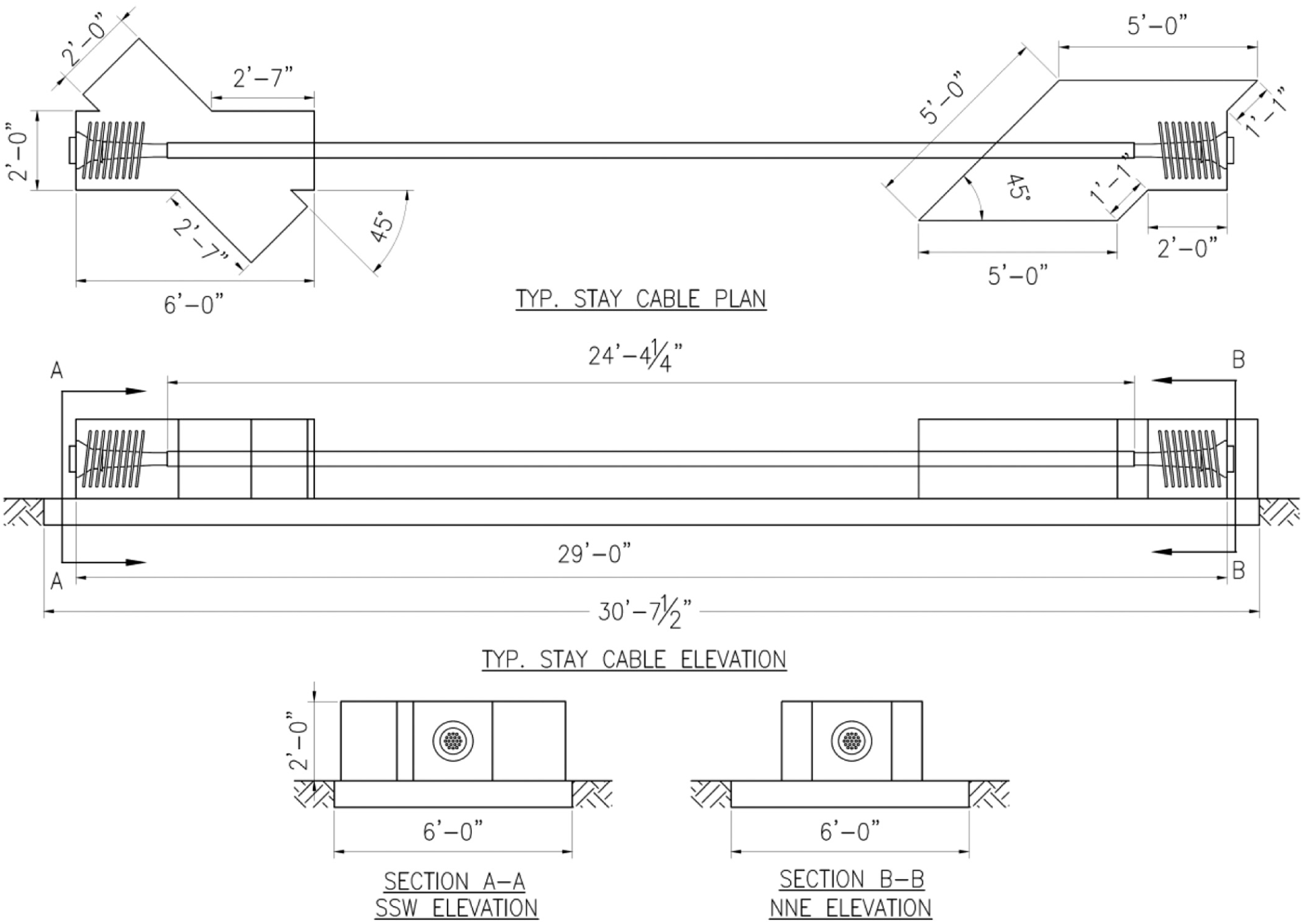
Geometric details of stay cable mock-up specimens.
After construction of the anchorage regions and placement of the ducts, the strand defects were placed and documented prior to grouting. Stay cable specimen 1 (SC1) and stay cable specimen 2 (SC2) have low-relaxation parallel strands, and grout was used as the corrosion protection system. Steel and HDPE ducts were used for SC1 and SC2, respectively. Stay cable specimen 3 (SC3) has ungrouted, greased and sheathed strands in HDPE duct, and stay cable specimen 4 (SC4) has epoxy-coated strands encased within HDPE ducts. Although SC3 and SC4 have no grout defects, they are part of a larger study to identify NDE technologies capable of detecting both grout and strand defects (which is not a subject of discussion in this manuscript). For the ungrouted specimens, the top three strands in each duct were stressed to a load of approximately 12 kips to ensure that the tendons were taut, resulting in minimum deflection, and sagging of the tendons.
Both strand and grout defects were implemented into each of the four stay cable specimens. To facilitate the placement of the various defects, each mock-up specimen was divided into segments that were approximately 3 ft long. The specimens contained two defect locations within the anchorage regions, and six defect locations along the free spans. As strand defects are not part of this investigation, only the grout defects are described further in detail. Table 1 provides the location of the grout defects and a description of all the grout defects in the stay cable specimens, including the level of severity for each defect. The grout defects were implemented in SC1 and SC2 at their respective locations, and the remaining sections were grouted completely with normal grout. Further details about the stay cable specimen construction, defect fabrication, and defect placement may be found in Hurlebaus et al. ( 6 ).
Location and Description of Defects in the Stay Cable Specimens
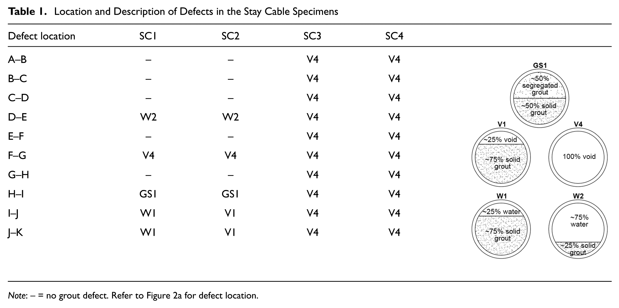
Note: – = no grout defect. Refer to Figure 2a for defect location.
Evaluation of Grout Defects in Stay Cable Specimens
The grout defects in the stay cable specimens were inspected using electromagnetic methods, mechanical wave and vibration methods, and visual methods.
Ground Penetrating Radar (GPR)
GPR is an electromagnetic technique, in which electromagnetic pulses are emitted from a transmitter and the reflected pulses are received using receivers. A variation in the material’s electrical conductivity and dielectric permittivity results in a difference in the reflected pulses. By analyzing the reflected pulses, it may be possible to identify anomalies in the structure.
A StructureScan Mini HR GPR unit with an operating frequency of 2.6 GHz was used in this investigation. This frequency allows for good resolution and a scan depth of up to 16 in. As the survey wheels on the device move along the length of the structure being investigated, the data is recorded. A 2.0 in. grid system was created for inspecting grout defects in the anchorage regions of the stay cable specimens. The scan was performed along vertical and horizontal lines, and later combined in the RADAN software to generate 3-D models of the anchorage regions. To enable the inspection of the MTEs, temporary wooden supports were installed on either side of the MTEs to allow the survey wheels to turn as the device moved.
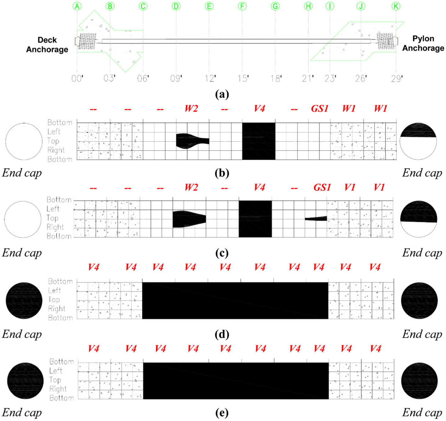
Figure 2 presents a comparison of the GPR testing results of the MTEs of the stay cable specimens with the actual defects. Figure 2b shows the inspection results of the metal duct in specimen SC1. It is evident that this method was unable to detect the air voids and the water infiltration defects within the metal duct. Figure 2c shows the GPR inspection results of the HDPE duct in specimen SC2. As seen in the figure, GPR signal over regions with air void and water infiltration were distinct with scattered bands when compared with the other regions with solid grout. However, the air voids and water infiltration could not be differentiated from each other. Figure 2d, e present inspection results from specimens SC3 and SC4, respectively. The GPR signals do not show solid bands along the length of the duct, leading to the conclusion that specimens SC3 and SC4 may be either completely void or filled with water. Owing to the rebound of the radar signal from the internal prestressing strands, it was not possible to determine the size of the void or water infiltration for any specimen.
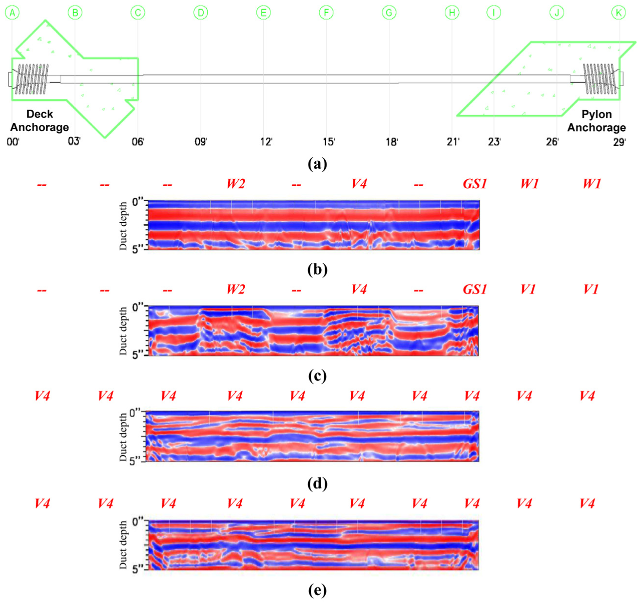
GPR inspection of stay cable specimens: (a) segments for defect placement within stay cable specimens; comparison of defects with GPR results from MTEs of (b) SC1, (c) SC2, (d) SC3, and (e) SC4.
The GPR technique was also used for the inspection of the anchorage regions. However, due to the large amounts of reinforcing steel in the anchorage regions, it was unable to even locate the metal ducts in the deck and pylon anchorage regions. Owing to its poor performance in detecting grout defects in the anchorage regions, the results are not presented herein.
Infrared Thermography (IRT)
IRT inspection is an electromagnetic technique and uses the principle of examining the emissivity of individual materials within the object being inspected. Depending on the emissivity, each material releases or absorbs heat at different rates, and the differential temperatures during this transition period can provide valuable information about the inner composition of the object. However, it is important to perform IRT during times of the day when atmospheric temperature gradients are high, thus forcing the object being inspected to heat or cool in order to reach equilibrium with the surrounding environment.
Passive IRT was used to inspect defects in the free spans of the MTEs, the anchorage regions, and end caps of the stay cable specimens. Note that active IRT was not pursued in this investigation, as it is impractical to use an external source of heat to inspect large regions of in-service structures. A high-performance, forward-looking infrared (FLIR) T640 thermal imaging camera was used for the IRT inspection. The accuracy of the camera was calibrated within ±3.6°F or ± 2% of the measurement at 77°F nominal temperature. To enable the inference of IRT inspection results, infrared images were captured at regular intervals starting before sunrise during the heating-up period. An appropriate scale was chosen to enable the detection of defects.
Figure 3a( i , ii ) presents the infrared images of the MTEs of the stay cable specimens. In both the images, specimen SC1 is at the back of the image and SC4 is in the front. The voided regions of the stay cable specimens are not evident in Figure 3a(i) but may be clearly distinguished from the completely grouted sections in Figure 3a(ii), which were taken roughly 100 minutes after sunrise. The water defect in section D–E of specimen SC2 appears to be similar to the air void in section F–E, indicating that water infiltration and air voids may not be differentiated in the infrared images.
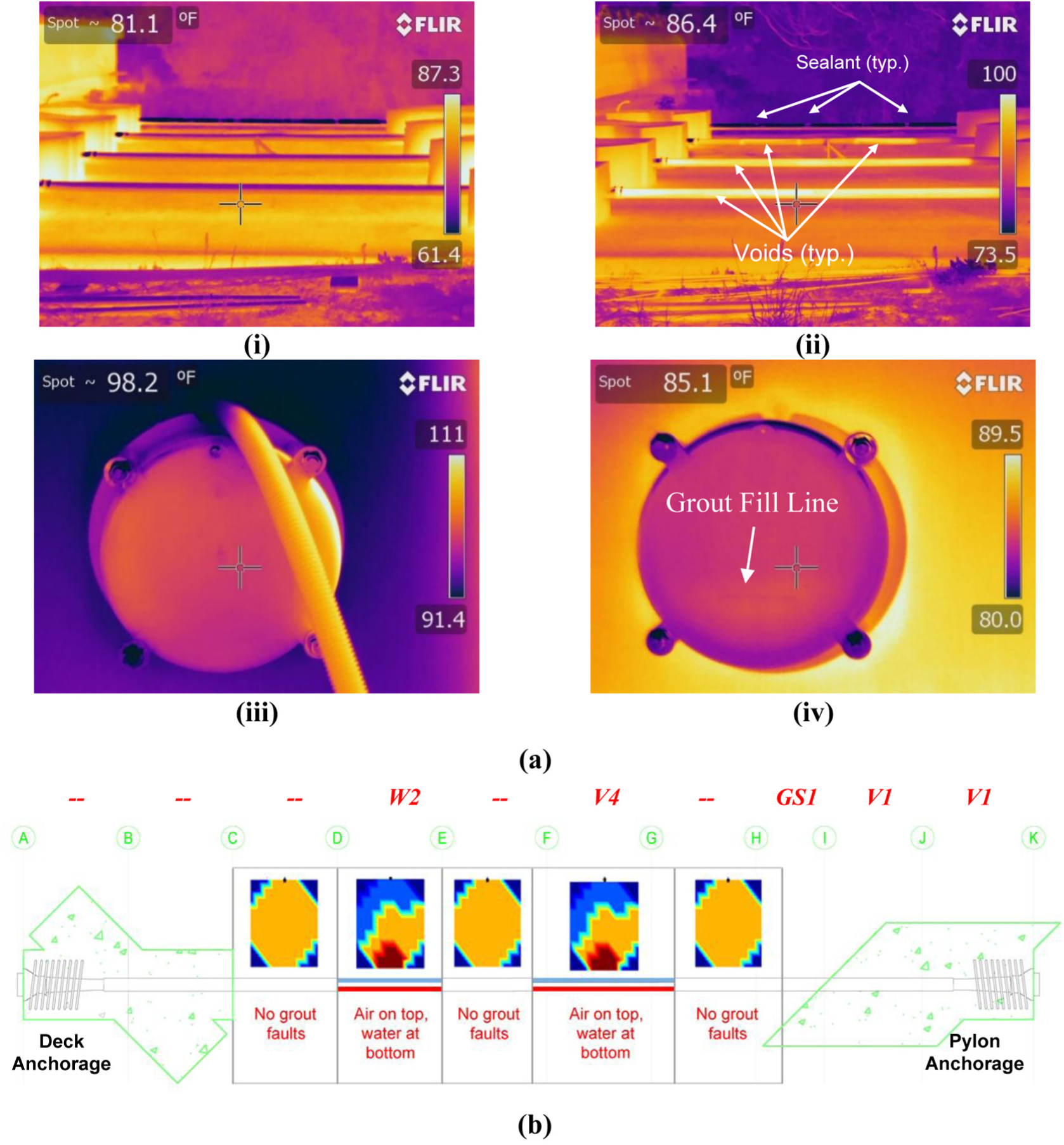
IRT and ECT inspection of stay cable specimens: (a) IRT images of (i) stay cable specimens approx. 7 min after sunrise, (ii) stay cable specimens approx. 100 min after sunrise, (iii) end cap region at deck anchorage of SC2, and (iv) end cap region at pylon anchorage of SC2; (b) comparison of results from ECT with the defect key of SC2.
It is important to note that the voided regions in specimen SC1 were not identifiable in the infrared images. This may be attributed to the low emissivity of steel, meaning that steel reflects significantly more heat than the HDPE ducts. This characteristic results in steel ducts absorbing significantly less heat and as a result being continually closer to thermal equilibrium with the environment, thus not allowing thermal differential between the voids and the fully grouted regions. However, the sealant between grouting defects in the metal duct may be identified in all the images, as it is a polyurethane compound which absorbs practically no heat and remains at a constant temperature despite environmental temperature changes.
The infrared images of the anchorage regions did not provide any discernable information (and hence are not shown) and were unable to even locate the metal ducts within the anchorage regions of the stay cable specimens. From this it is evident that the IRT inspection technique is not applicable in inspecting defects within the metal ducts embedded in the deck and pylon anchorage regions.
Figure 3a( iii , iv ) shows infrared images of the end caps of the specimen SC2 in the deck and pylon anchorage regions. The infrared image of the end cap in the deck anchorage does not show the presence of any differential temperature, indicating that the end cap is either completely filled with grout or completely empty. However, the infrared image of the end cap in the pylon anchorage shows a discernable grout fill line, indicating that the end cap is partially filled.
Electrical Capacitance Tomography (ECT)
ECT is an electromagnetic technique and has the advantage of being a safe, fast, and relatively inexpensive technique. ECT obtains capacitance data from multi-electrode sensors, and by several iterations makes permittivity images of sections. ECT has been primarily applied to detect the air pockets in oil flow. However, there are inherent problems with the image resolution which is a major roadblock in the application of this method. In this investigation, ECT was used to detect grout defects in the free spans of the MTEs.
The inspection process involved identifying the beginning and ending points of voids, water, and bleeding grout in real time. ECT is not applicable to metal ducts, therefore only SC2 with grouted HDPE ducts was part of this investigation. Figure 3b shows a comparison of the results from ECT for SC2 with the defect key. Although ECT was able to identify the location of the water and air defects with good accuracy, the cross-sectional slices indicated the presence of both water and air at locations having only water infiltration (section D–E) and air void (section F–G). The method was not able to identify compromised grout (section H–I).
Impact Echo (IE)
IE inspection was performed on the anchorage regions of the stay cable specimens to determine the grout defects within the metal ducts embedded in these zones. The top of the deck and pylon anchorages of all four stay cable specimens were inspected at 6 in. intervals. The technique involves hitting the surface with a small impactor or impulse hammer and identifying the reflected wave energy with a displacement or accelerometer sensor mounted on the surface near the impact point. The IE tests were performed using an IE scanner test head and a PC data acquisition system. An IE velocity of 13,123 ft/s was used for the calculation of concrete thickness.
The IE testing of the anchorage regions of the stay cable specimens provides poor quality data with weak and inconsistent resonant echoes. The cross-sectional dimension of the anchorages is approximately 2 ft × 2 ft, which exceeds the range of the practical limit of the IE device. Also, IE data is clearest on plate-like structures such as walls and slabs; whereas structures with greater depth naturally produce multiple resonances due to the structure geometry, which can complicate the data analysis. As there is no conclusive information about the grout condition within the ducts in the anchorage regions, the IE inspection data from the stay cable anchorages is not presented herein.
Sounding
Sounding is a simple acoustic NDE method that can be used to inspect different bridge components, including the MTEs of cable-stayed bridges. Sounding is performed by tapping an impactor along the MTE of the stay cable specimen and listening for a change in the acoustic response produced by the tapping. Tapping on an area of the voided duct creates a different sound pitch, which indicates the potential presence of a voids. By recording areas of lower pitch responses corresponding to voids, a map of voided areas can be produced, and these locations can be marked for further inspection.
Inspection of the MTE along the length of the duct was conducted for all four stay cable specimens. The inspections were performed at 12 in. intervals. Sounding inspection was also conducted on the end caps of the anchorage systems by tapping the grout caps. The results from the sounding inspection were included in the void mapping sheets shown in Figure 4. The sounding maps provided accurate information on voided regions existing within the ducts. However, sounding did not differentiate between voided regions, water infiltrated regions, and regions with poor grout.
Figure 4 shows a comparison of the sounding inspection results with the defect key for each specimen. The voided and water infiltration regions along the free span of the MTEs and the end caps in the anchorage regions can be clearly identified from the sounding map. While the segregated grout defect in specimen SC1 with the metal duct could not be identified, the same defect in the HDPE duct in specimen SC2 is identifiable. This is due to the relative difficulty of interpreting the lower pitch sounds created when tapping on the metal ducts. Due to the interpretation of acoustic responses by the inspector, sounding is a subjective method and data can vary from each trial and inspector, especially for metal ducts. Sounding maps for specimens SC3 and SC4 clearly indicate ungrouted MTEs.
Comparison of results from sounding with defect key: (a) defect locations within stay cable specimens; (b) SC1; (c) SC2; (d) SC3; (e) SC4. Note: Regions shaded black represent low ringing sound corresponding to grout defect.
Sounding was very effective in determining the grout condition in the end cap. The partial and full voids in the end cap regions can also be clearly identified. However, as expected, sounding through mass concrete was not able to determine any useful information about the defects in embedded ducts in the anchorage regions.
Ultrasonic Tomography (UST)
The anchorage regions of the stay cable specimens were inspected using UST. In this technique, the emitted ultrasonic waves are reflected at material interfaces due to a change in acoustic impedance. Consequently, UST was used to identify grout defects within the metal ducts in the anchorage regions of the stay cable specimens. Considering that the top of the deck and pylon anchorages of the stay cable specimens would be accessible in an in-service cable-stayed bridge, these regions were inspected using UST. To facilitate the inspection, a 2 in. × 2 in. grid system was made on the deck and pylon anchorage regions. The A1040 MIRA was used in this investigation. The operational frequency was set to 50 kHz, and the specimen was scanned with the device oriented both parallel and perpendicular to the longitudinal axis of the MTEs.
Figure 5a( i , ii ) shows a representative 3-D map created from the UST scanning of the anchorage regions of specimen SC1. Although the duct underneath the top reinforcement is visible, it is unable to conclusively decipher the grout defects within the metal ducts embedded in the anchorage regions. Figure 5a( iii , iv ) presents the D-scans through the embedded metal ducts of the deck and pylon anchorages of specimen SC1. The images through the duct do not show any indication of grouted, ungrouted, or water infiltrated sections.
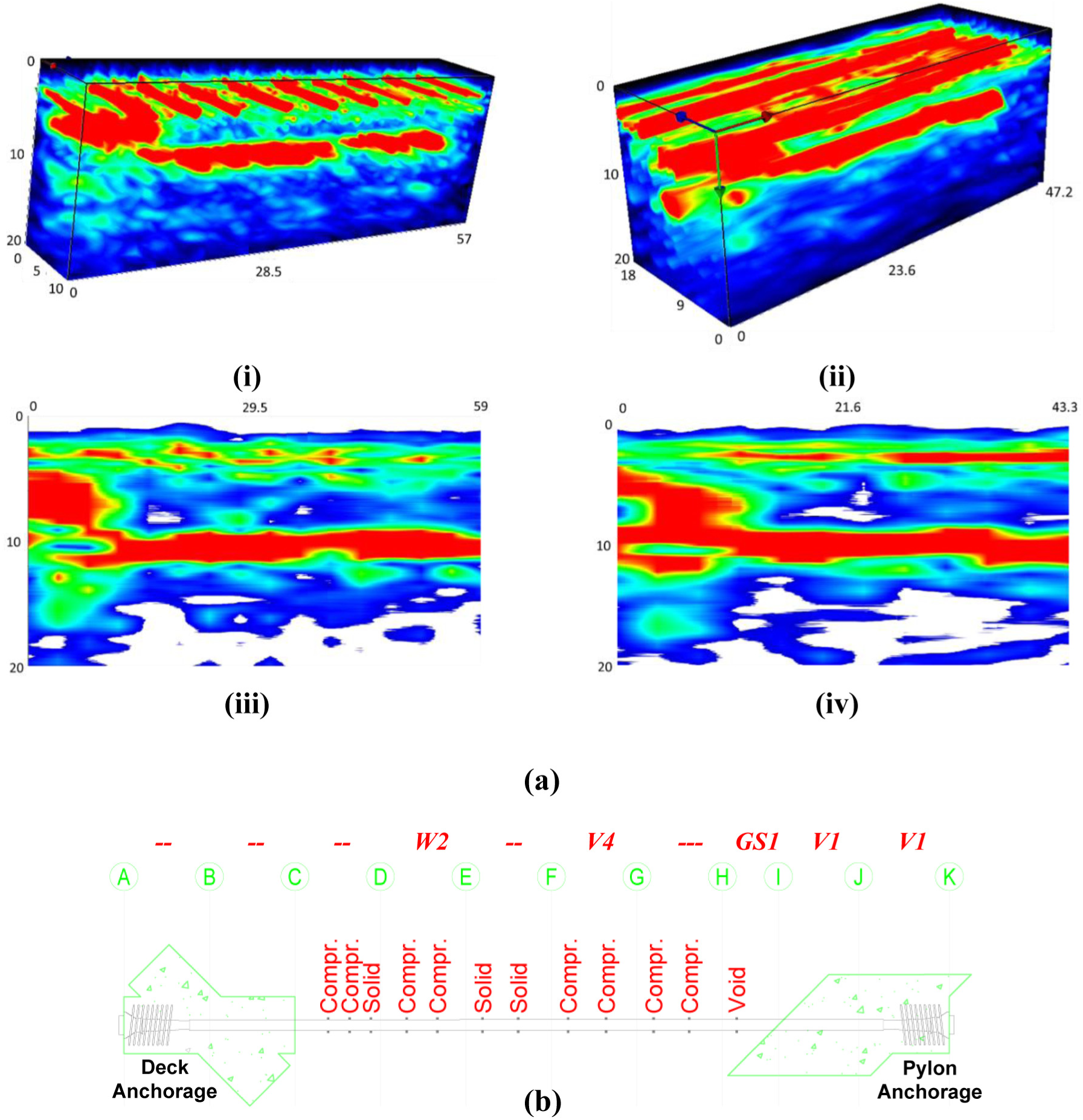
Results from UST and LFUT inspection of stay cable specimens: (a) UST inspection of anchorage regions of SC1 showing (i) 3-D map of deck anchorage parallel scan, (ii) 3-D map of pylon anchorage perpendicular scan, (iii) D-scan of deck anchorage perpendicular scan, and (iv) D-scan of pylon anchorage perpendicular scan (all units in inches); (b) comparison of results from LFUT with the defect key of SC2. Note: Solid = no grout defect; Compr. = water infiltration or segregated, unhydrated or gassed grouts; Void = void defect.
Ultrasonic Pulse Velocity (UPV)
Inspection using UPV was performed on the deck and pylon anchorages of selected stay cable specimens to assess the grout condition within the ducts in these regions. Two 50 kHz ultrasonic transducers were used as an emitter and receiver. The testing was performed at two heights through the anchorage region, one at 12 in. from the top face, which is through the centerline of the embedded duct; and the second at 31.5 in. from the top surface, which provides a velocity baseline. Results from UPV inspection along these two locations show no apparent difference in the direct velocity, which suggests that the UPV method is not sensitive to the grout conditions within the ducts. One of the reasons that UPV is not sensitive to the defect is likely due to the small size of the defect relative to the length of the test path.
Low Frequency Ultrasound (LFUT)
LFUT was used to assess the grout condition in the MTE of specimen SC2 with grouted HDPE ducts. The LFUT system is designed to generate and receive low frequency ultrasonic waves in a pitch-catch fashion, which propagates across the cross-section of the duct. The grout conditions identified by LFUT are reported to be either solid (no defects), compromised (which includes water infiltration and segregated, unhydrated, and gassed grouts), or void. The measurements were performed at intervals of 12 in. to 18 in. along the length of the ducts.
Figure 5b presents a comparison of actual defect locations with the results from LFUT for specimen SC2. The water infiltration (section D–E) and air void (section F–G) are reported as compromised grout (compr. in Figure 5b). The segment of the stay cable with segregated grout (section H–I) is reported as a void. Section E–F, which has good grout, is reported to have solid grout. However, other segments of the specimen (C–D and G–H) without any grout defects are reported to have compromised grout.
Visual Testing (VT)
Currently, VT is the most common method of inspection of the MTEs of a stay cable. This entails a trained inspector monitoring the MTEs for indicators of physical changes that may be detrimental to the structure. As the grout is enclosed within opaque ducts, the true condition of the grout cannot be determined without opening the duct at the location of inspection. This means that detrimental conditions within a duct can often go undetected when inspection techniques are limited to visual inspection alone. In this investigation VT of the anchorage regions was conducted after removing the end cap. All eight end caps of stay cable specimens were removed and visually inspected, and then the photographed end cap conditions were compared with the actual defect key. Figure 6a shows two representative images of the end caps, which accurately identified the actual defect conditions, which are shown in parentheses.
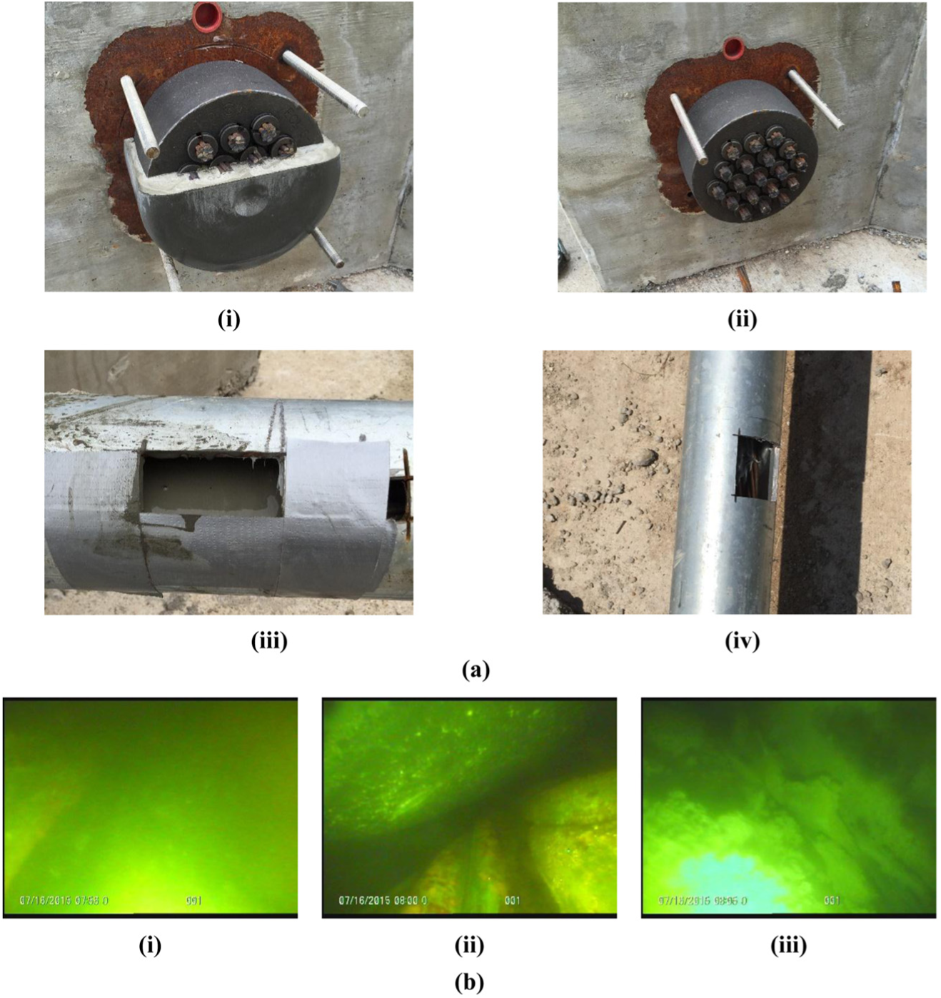
Results from visual inspection techniques: (a) representative end cap and open duct location photos for (i) SC1-pylon anchorage (W1), (ii) SC3-pylon anchorage (V4), (iii) SC1 section D–E (W2), and (iv) SC1 section F–G (V4); and (b) borescope inspection photos of SC2 (i) section D–E (W2), (ii) section F–G (V4), and (iii) section H–I (GS1).
Similarly, visual testing was also conducted through the small cut outs on the ducts that were introduced during the construction phase for placing the defects into the ducts, as shown in Figure 6a( iii , iv ). Visual testing is very useful for identifying the defect condition and severity, but typically it may not be possible to detect the location of the defect at early stages.
Borescope
Borescope inspection is a visual technique that can be used to inspect hard-to-reach places. Borescope inspection of the MTEs was performed using an Olympus IPLEX SX II apparatus to identify and provide visual information about the condition of the grout within the duct. Borescope inspections are relatively slow, but they provide the user with the ability to visually examine the conditions that exist within the duct. Although this method is useful for determining the severity of voids, it is essential that a void is present for the camera to physically enter the duct. Owing to this accessibility requirement, borescope inspection is referred to as a semi-destructive method. Depending on the system of stay cables, grout ports or grout caps may be temporarily opened for inserting the borescope tube. Therefore, it may be a very useful method in anchorage regions where the grout inlet/outlets can be opened for inspection and closed afterwards.
Borescope not only allows the inspector to view the grouting conditions, but also to qualitatively evaluate the severity and shape of the defects in order to recommend remediation techniques. This method does not have the ability to locate detrimental conditions by itself, so it is usually preceded by other inspection methods; usually visual testing or sounding is used to locate voids.
In this investigation, threaded entry holes were drilled into the ducts during construction and later used as entry ports for the borescope tube. These holes were sealed with a screw-in plug when not in use to protect the integrity of the defects. In addition to the drilled holes, grout ports were also used as entry points. Even with the presence of drilled holes, entry access was not necessarily available in each section, as fully grouted sections did not allow access of the camera even after the plug was removed.
Figure 6b shows representative borescope images of water infiltration, voided regions, and segregated grout conditions. The still photos appear blurry due to distortion, but video data and live operation of the device clearly showed that the camera was moving through water. Figure 6biii shows the segregation of grout along the top of specimen SC2 in section H–I.
Discussion of Results
Based on the test results, Table 2 presents a summary of the capability of the various NDE techniques in locating the voids, water infiltration, and segregated grout conditions in both metal and HDPE ducts of the MTEs, and the anchorage regions of the stay cable specimens. The electromagnetic methods used for the inspection of grout defects within the MTEs of the stay cable specimens include GPR, IRT, and ECT. Among these, all the methods were able to identify the location of the voids and water infiltration defects within the HDPE ducts. However, they could not differentiate between the two defects. In addition, the methods were not applicable to metal MTEs, and could not differentiate between compromised grout conditions and intact grout. GPR and ECT were unable to provide any quantitative or qualitative information regarding the depth of the void or grout quality within the duct. Although IRT could make some estimates about the size of the defect, the accuracy associated with determining the severity of the defects is low.
Capability of NDE Techniques to Detect Grout Conditions in MTEs and Anchorage Regions of Stay Cable Systems
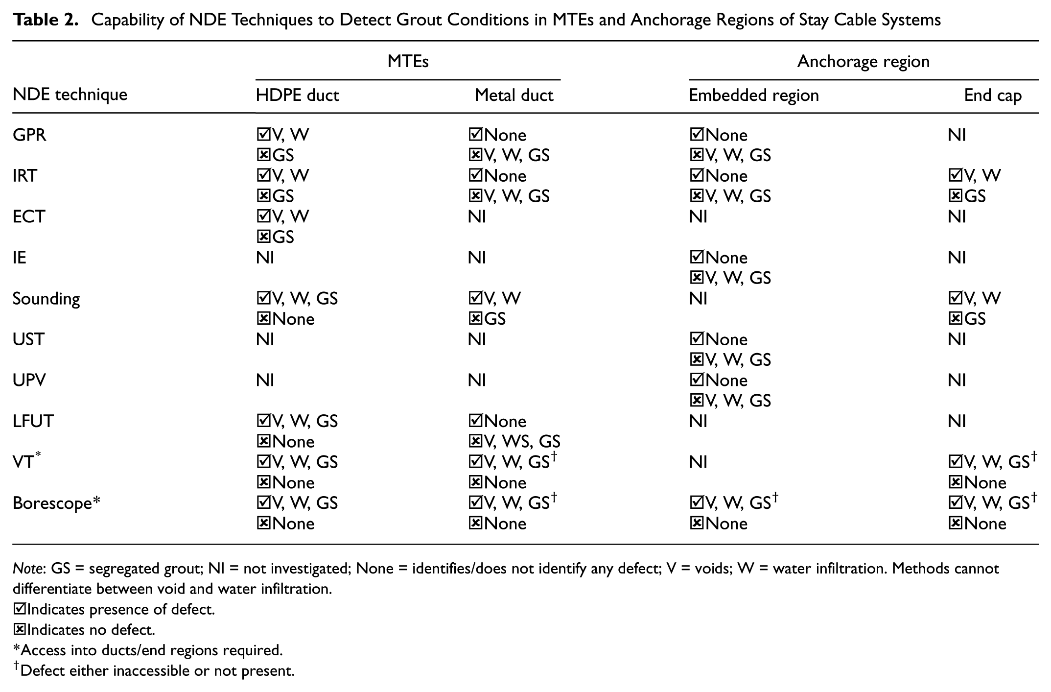
Note: GS = segregated grout; NI = not investigated; None = identifies/does not identify any defect; V = voids; W = water infiltration. Methods cannot differentiate between void and water infiltration.
☑ Indicates presence of defect.
☒ Indicates no defect.
Access into ducts/end regions required.
Defect either inaccessible or not present.
All electromagnetic methods were ineffective in identifying the grout defects in the metal ducts embedded within the anchorage regions. While GPR and ECT cannot be used for the inspection of the end caps in the anchorage region, IRT could be effectively used to identify partially filled end caps. However, if the end cap is completely void or filled with grout, then it is not possible to identify the actual condition within the end cap using IRT alone. IRT can also be used to identify the severity of the voids in the end cap regions with good accuracy.
The vibration methods used for the inspection of grout defects in the stay cable specimens include IE and sounding. IE was used for the inspection of the anchorage regions, and sounding was used for the inspection of the MTEs and the end caps of the stay cable specimen. IE did not provide any discernable information regarding the grout defects within the metal ducts embedded in the anchorage region, whereas sounding was very effective in providing information about the location of the voids and water infiltration defects within the MTEs and the end caps. However, differentiation between the voids and water infiltration defects was not possible. Sounding was also not effective in identifying grout defects within the metal ducts.
The inspection techniques involving ultrasonic waves included UST, UPV, and LFUT. UST and UPV were used for the inspection of the anchorage regions of the stay cable specimens. Neither of these methods were successful in detecting grout defects within the anchorage regions due to heavy steel reinforcement around the metal ducts. LFUT was used for the inspection of grout defects in the MTE of specimen SC2, as this was the only grouted MTE with HDPE ducts. LFUT could identify the void and water infiltration in the MTE but could not differentiate between these conditions. The method also incorrectly identified intact sections as sections with compromised conditions.
Visual testing and borescope techniques were also used for inspecting the grout conditions in the stay cable specimens. These methods are effective once the approximate locations of the grout defects are known through other inspection techniques. The two methods were able to identify the defective grout conditions in regions with sufficient accessibility. However, for both the techniques obtaining access to certain regions to carry out the inspection can be a major challenge. Borescope inspection is an ineffective tool for detecting grout defects by itself. However, it can be very useful as an evaluative tool when coupled with another NDE method that can locate defects.
Conclusions
To evaluate the effectiveness of various NDE techniques in detecting grout defects in stay cables, four stay cable specimen mock-ups were built with known grout defects. Several NDE techniques that may be broadly classified as electromagnetic methods, vibration methods, ultrasonic methods, and visual methods were used for the inspection of grout defects in the stay cable specimens, and the following observations were made:
IRT, sounding, and the visual inspection techniques were able to identify the voids and water infiltration defects in the end cap regions.
GPR, IRT, ECT, sounding, and LFUT were capable of identifying grout defects in the MTEs with HDPE ducts.
Methods other than sounding, visual testing, and borescope were either ineffective or not applicable to metal ducts.
The NDE methods used in this investigation were capable of identifying potential vulnerable locations in the stay cable, however they could not differentiate between voids and water infiltration defects.
The compromised grout conditions in the MTEs were not identified by the NDE methods considered in this investigation.
Detecting grout defects located within metal ducts in the anchorage regions is still a challenge. This is attributed to the greater attenuation of signals due to the increased thickness of the concrete block, and the greater steel reinforcement ratio in the anchorage region.
Footnotes
Acknowledgements
This project was sponsored by the American Association of State Highway and Transportation Officials, in cooperation with the Federal Highway Administration, and was conducted through the National Cooperative Highway Research Program (Grant No. NCHRP 14-28). The project team would like to thank the Senior Program Officer, Dr. Waseem Dekelbab, and all NCHRP panel members, for their input during the various phases of the project. The authors would also like to thank Mr. William R. ‘Randy’ Cox (ASBI) for his support for grouting certification training; and Mr. John Turner and Dr. Mike Mota (CRSI), Mr. Pete Diggs and Mr. Bryan McMurray (Gerdau Long Steel North America), Dr. Zuming Xia and Mr. John Crigler (VSL), Mr. Ray Bauer (Commercial Metals Company), Mr. Mark Huff (BASF), and Mr. Steve Koch (Sumiden Wire Products) for their in-kind contribution of material for the construction of the mock-up specimens. The authors also thank the various industry partners for conducting NDE inspection of the stay cable specimens.
Author Contributions
The authors confirm contribution to the paper as follows: study conception and design: Dr. Stefan Hurlebaus, and Dr. Mary Beth D. Hueste; data collection: Dr. Madhu M. Karthik, Dr. Tevfik Terzioglu, and Mr. Casey Jones; analysis and interpretation of results: Dr. Madhu M. Karthik Dr. Tevfik Terzioglu, and Mr. Casey Jones; draft manuscript preparation: Dr. Madhu M. Karthik, and Dr. Tevfik Terzioglu. All authors reviewed the results and approved the final version of the manuscript.
The Standing Committee on Testing and Evaluation of Transportation Structures (AFF40) peer-reviewed this paper (18-04206).