
Abstract
To evaluate transverse cracks on a semi-rigid asphalt pavement by falling weight deflectometer (FWD), a three-dimensional (3D) dynamic finite-element (FE) model to calculate the deflections of transverse-cracked semi-rigid asphalt pavements under FWD loading was developed and validated by in-situ FWD tests. Then, the effect of crack types and crack width on the deflection basin was investigated for semi-rigid asphalt pavements under different interlayer contact conditions. The relationship between transverse cracks and deflection basin parameters (DBPs) was also analyzed. Finally, the slope ratio to evaluate transverse cracks was proposed and validated by field application. Results show that cracks on pavements will make the deflection basin steeper and the crack width slightly affects the deflections for the same type of crack without interaction between adjacent cracking surfaces. Results also indicate that deflection values increase obviously when the surface-base interaction changes from “Full bonded” to “Full slip.” In addition, results indicate that the slope index (S1), the shape index (F2), and the area index (AREA) correlate well with transverse cracks, and the surface cracking, “Reflective cracking 1” (surface and base cracking simultaneously), “Reflective cracking 2” (surface, base, and subbase cracking simultaneously) and the hidden cracking (base cracking, or base and subbase cracking simultaneously) can be identified by the slope ratio. Field application also indicates that the slope ratio can be applied to evaluate the types of transverse cracks on semi-rigid asphalt pavements.
A semi-rigid asphalt pavement, which has at least a course with the stabilized layer as a base or base and subbase below the asphalt concrete surface layer, is the primary pavement structure in China ( 1 , 2 ). Transverse cracks, especially the reflective cracks, are the common form of cracks on semi-rigid asphalt pavements ( 3 ). The existence of cracks affects the performance of the road and also the evaluation of physical properties, such as the modulus back-calculation ( 4 ). Thus, it is significant to evaluate the cracks on semi-rigid asphalt pavements.
As falling weight deflectometer (FWD) has been widely used, non-destructive testing becomes a common method to evaluate the performance of pavements. One of the applications is to evaluate the transverse cracks of pavement structures ( 5 ). Uddin et al. ( 6 ) conducted a dynamic analysis of the damaged pavement structure under discontinuous conditions. The results show that the deflection of pavement increases by 17% when cracks appear and the FWD deflection basin test results at the crack location cannot be used for the modulus back-calculation. Grenier and Konrad ( 7 ) have found that the pavement deflection basin significantly changes before and after cracking, and the deflection basin will sink after cracking. Qiu et al. ( 4 ) also found that cracks of asphalt pavements significantly affect the FWD deflections. It is recommended that the deflection basin parameters (DBPs) be used directly instead of the structural layer modulus to evaluate the effect of cracks on the pavement structure. Lee ( 8 ) suggested that different types of surface cracks can be identified by the relationship between the shape parameter F2 and the area index AERE. In addition, Cong et al. (9) proposed a new parameter called pavement structure condition efficiency (PSCE) to differentiate the thermal crack and the reflective crack. Recently, Deng and Yang applied load transfer efficiency (LTE) to determine the transverse cracking types on the surface layer based on the FWD deflection data ( 10 ).
Thus, previous research results revealed that cracks correlated well with the deflection basin data. It is helpful to evaluate the cracks of asphalt pavement base on the shape or value of the deflection basin. Usually, the shape or value of the deflection basin can be characterized by DBPs ( 11 ). Therefore, the main objective of this paper is to study the relationship between transverse cracks and DBPs, and then find a practical method to evaluate the transverse cracks of semi-rigid asphalt pavements.
Based on the evaluated local road in Shanghai, a three-dimensional (3D) finite-element (FE) model was developed to simulate intact and transverse-cracked semi-rigid asphalt pavements under FWD loading. The model was validated by the deflection basin data measured from FWD tests. The influences of crack types and crack width on the deflection basin were investigated for semi-rigid asphalt pavements under different interlayer contact conditions with the developed 3D FE models. The relationship between cracks and DBPs was analyzed. Finally, the slope ratio to evaluate the transverse crack was proposed and validated by field application as well.
Development of 3D FE Models
Pavement Structure and Material Properties
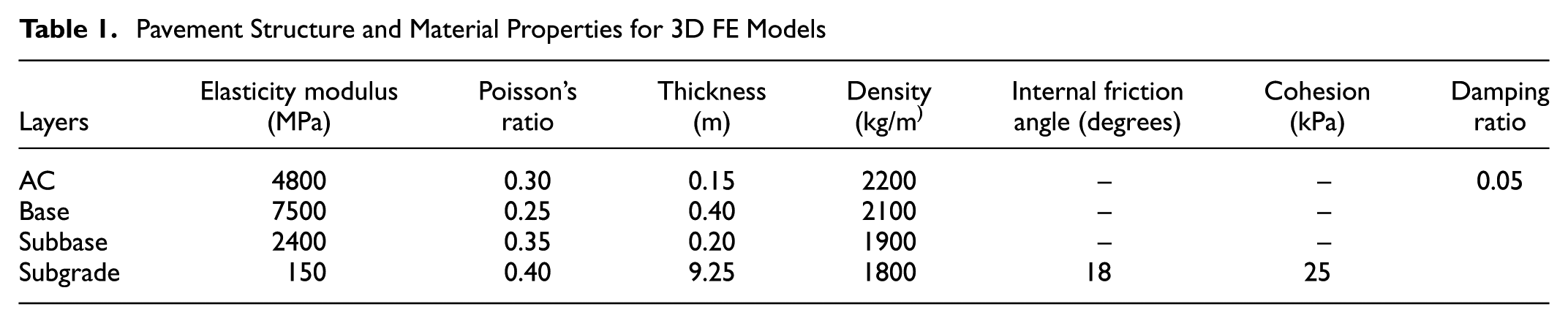
The pavement structure analyzed in this paper is based on the evaluated road in Shanghai, which is the typical semi-rigid pavement in China. The pavement has four layers, which are the surface, base, subbase, and subgrade. The thickness of each layer is shown in Table 1. The surface layer consists of asphalt concrete (AC), whereas the base and subbase consist of cement stabilized crushed stone and cement-treated soil, respectively. Materials of surface, base, and subbase were assumed to be isotropic and linearly elastic characterized by their elasticity modulus and Poisson’s ratio. The material of subgrade was elastoplastic and the Drucker-Prager model was utilized in this study. The values of elasticity modulus and Poisson’s ratio were determined by modulus back-calculation referring to previous research ( 12 , 13 ), and the layer properties at 25°C were adopted. The internal friction angle and cohesion of subgrade soil were obtained from the direct shear test ( 14 ). In addition, Rayleigh damping was used as the damping scheme. The value of damping ratio was set to 0.05 according to the related study ( 15 ). Finally, all the material parameters are summarized in Table 1.
Pavement Structure and Material Properties for 3D FE Models
3D FE Models for Asphalt Pavements with Transverse Cracks under FWD Loading
The 3D FE model was established using the ABAQUS program, as shown in Figure 1. In the vertical direction, the length of the model was considered to be 10 m, which is more than 50 times the plate-load diameter ( 16 ). Thus the depth of the subgrade was 9.25 m, as shown in Table 1. In the horizontal direction, the size is 10 m ×10 m referring to the results of Wei ( 17 ). “Full bonded,”“Partial slip,” and “Full slip” were considered for the interface interaction of surface and base layer. “Partial slip” was characterized with Coulomb friction and the friction factor (μ) can be determined by comparing computed deflections with in-situ measured deflections. In addition, the bonding conditions of all other interlayers were fully bonded, and the movement at the bottom of the model was restrained in all directions and the displacements of vertical faces were restrained in x- and y- axes. The model was meshed with eight-node solid brick elements. The size of the surface’s elements was 10 cm and finer mesh was applied to the loading zone. The size of elements for base and subbase was 20 cm whereas it was 50 cm for the subgrade. For the crack, the solid structure was applied in the model. Since crack width is generally wider than 0.2 mm in practice, the contact behavior between adjacent cracking surfaces were not considered ( 4 , 8, 17).
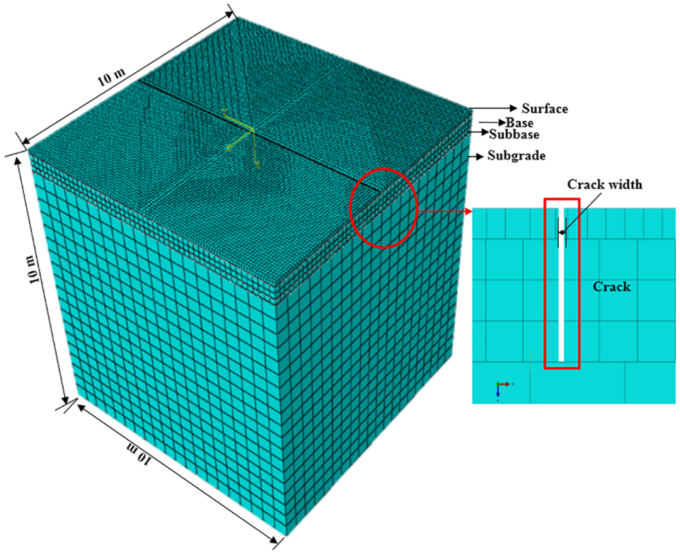
The 3D FE model established with the ABAQUS program.
A 50 kN peak dynamic load with an approximately 0.03-seconds half-wave sine pulse was applied in this study. It can be modeled with pseudo-static in the ABAQUS program. For the convenience of meshing, the circular loading area was converted into a square area with 266 mm lengths ( 4 , 17 ). The location of loading and nine deflection sensors (d1, d2, d3, d4, d5, d6, d7, d8, and d9) for FWD are illustrated in Figure 2.
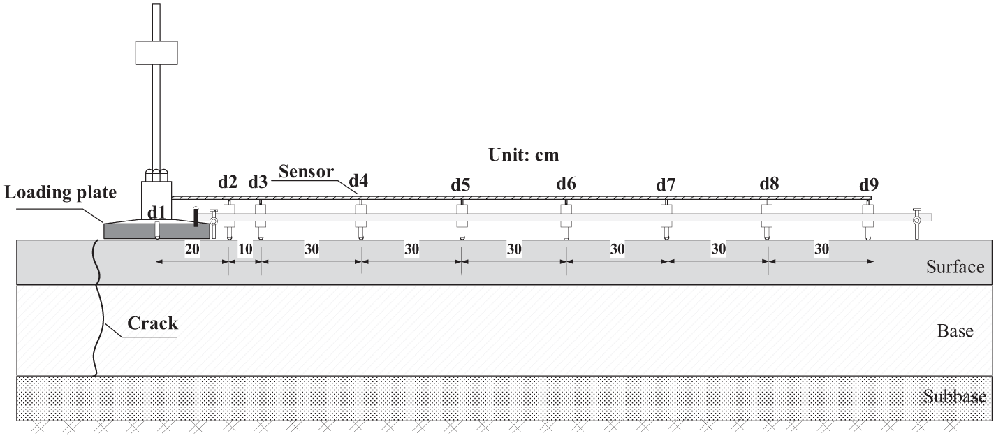
Loading location and sensor configuration of the applied FWD.
Models Validation
Deflection measurements were conducted with FWD on the evaluated road. The results can be utilized to verify the models established above.
Verification of Models without Transverse Cracks
Three sets of deflection basins were selected from the FWD testing on the intact pavements, which are shown in Figure 3. Cores drilled on the in-situ road showed that the interface of surface and base were bonded well. Thus, deflections of the intact pavements were calculated with the 3D FE model in the condition of “Full bonded.” The calculated results are also presented in Figure 3. Comparably, the model data can coincide well with the field data. The averaged maximum difference happens at the sensor of d3 and it is 3.9% of the averaged field data. Therefore, the model without transverse cracks can well simulate the deflection response of the intact pavements under FWD loading.
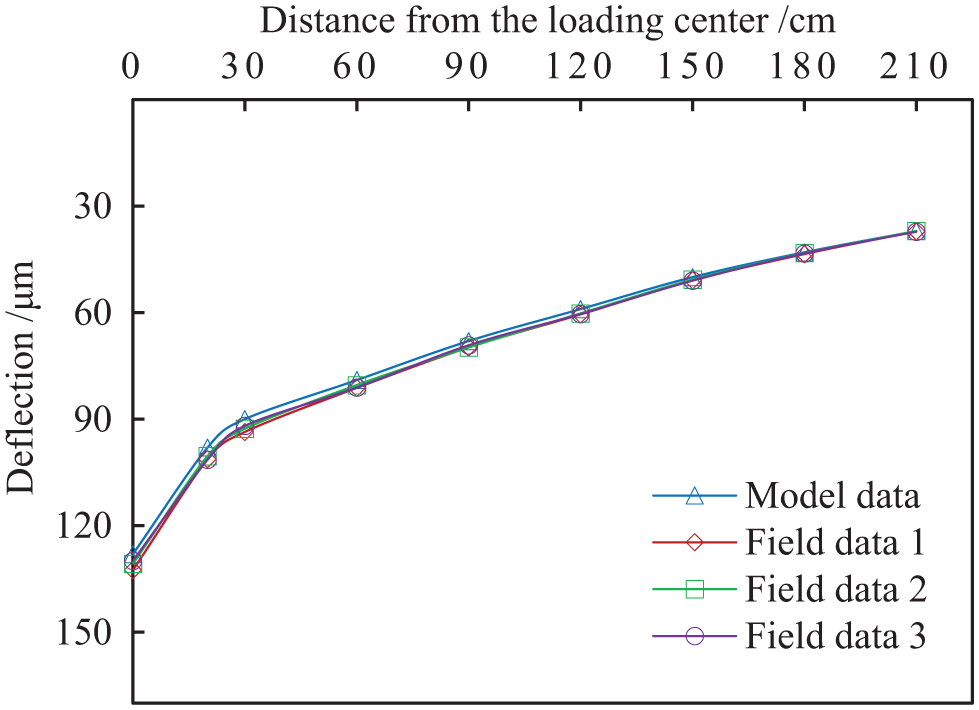
Validation of the 3D FE model without transverse cracks.
Verification of Models with Transverse Cracks
FWD testing was also conducted on the transverse-cracked pavements. Meanwhile, cores were drilled to identify the type of cracks and the crack width was measured as well. Finally, three sets of deflection basins on pavements with surface transverse cracks were selected and three sets of deflection basins on pavements with reflective transverse cracks (surface cracking and base cracking) were selected, which are presented in Figure 4, a and b , respectively. The corresponding 3D FE models were established according to the cracking type and the measured crack width. The analyzed results are also shown in Figure 4.
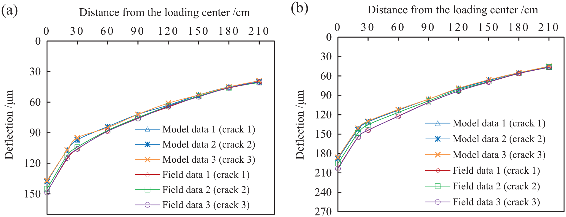
Validation of 3D FE models with transverse cracks: (a) surface transverse cracks; and (b) reflective transverse cracks (surface cracking and base cracking).
Comparably, the model data can coincide well with the field data for each crack. For surface transverse cracking, the maximum difference happens at the loading center of the deflection basin for “crack 2” and it is 8.7% of field data. For reflective transverse cracking, the maximum difference exists at the loading center of the deflection basin for “crack 3” and it is 9.1% of field data. Therefore, the pavement model with transverse cracks is reliable.
Results and Discussion
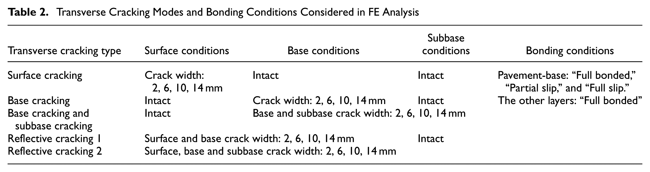
According to the survey results, this study considered different transverse cracking modes for semi-rigid asphalt pavements in different bonding conditions, which is shown in Table 2. Finally, a total of 60 models were analyzed.
Transverse Cracking Modes and Bonding Conditions Considered in FE Analysis
Effects of Transverse Cracks on Deflection Basins in Different Bonding Conditions
All analyzed results are presented in Figure 5. The deflections for the same cracking type in different bonding conditions are illustrated in one graph.
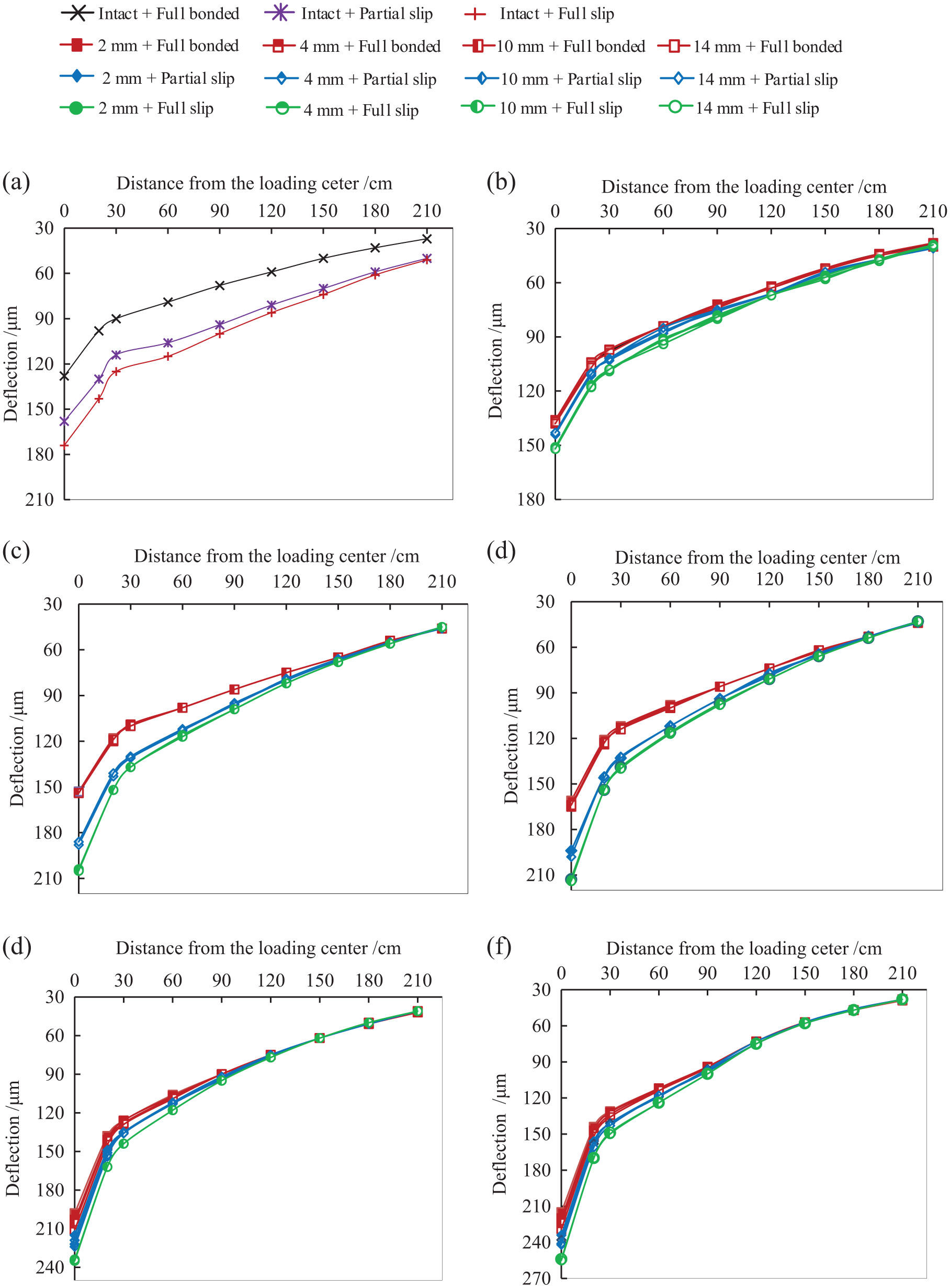
Results of deflection basins analyzed with 3D FE models: (a) intact, (b) surface cracking, (c) base cracking, (d) base cracking and subbase cracking, (e) reflective cracking 1, and (f) reflective cracking 2.
Figure 5 shows that cracks significantly affect the shape of the deflection basin. The existence of cracks will make the deflection basin steeper. For all types of cracks, the deflection values of cracked pavements will become larger compared with intact pavements. Concretely, the deflection value increases more obviously as the measuring point approaches the load center. At the measuring points far away from the loading center, the deflection basin of cracked pavements gradually converges to that of intact pavements. For the same type of cracks, the deflection values increase slightly with the crack becoming wider when the bonding condition is identical. This is because the analyzed crack widths that are common in practice, are bigger than 0.2 mm, in case of which there are no interactions between adjacent cracking surfaces. Comparably, the bonding conditions have more obvious influence on the values of the deflection basin. When the interlayer interaction changes from “Full bonded” to “Full slip,” the deflection value obviously becomes larger. It also implies that the bonding conditions can affect the modulus back-calculation ( 18 ).
Correlation between DBPs and Transverse Cracks
As investigated above, transverse cracks will affect the shape and value of the deflection basin for semi-rigid asphalt pavements. By now, many DBPs characterizing the shape and value of the deflection basin have been proposed to assess the structural conditions of pavements ( 19 ). In this study, the slope index, the shape index, the area index, and the deflection ratio index were selected to investigate the relationship between DBPs and transverse cracks of semi-rigid asphalt pavements. Previous research (20–22) found that the deflection basin in the range of 0 to 90 cm from the loading center reflects structural conditions of the base and surface. For the applied FWD, the sensor of d5 is 90 cm away from the loading center. Thus, d1–d5 were used to calculate the selected DBPs. Furthermore, transverse cracks with different types and widths in different bonding conditions were numbered. Spearman’s rank correlation coefficient (ρ) between DBPs and transverse cracks was calculated, as shown in Table 3.
Correlation Analysis Results between DBPs and Transverse Cracks
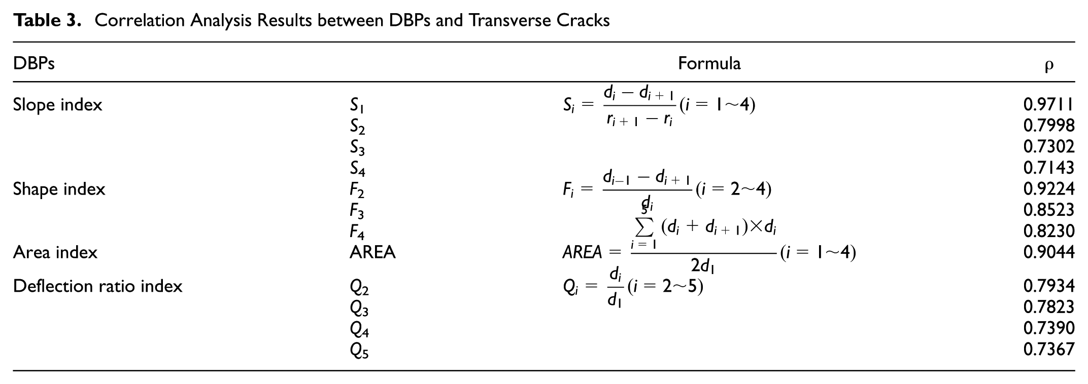
It can be observed from Table 3 that S1, F2, and AREA are correlated well with transverse cracks (ρ > 0.9). It indicates that transverse cracks of semi-rigid asphalt pavements can be evaluated by the aforementioned DBPs.
Evaluation Indicator and Criteria for Transverse Cracks
Comparably, S1 is correlated best with transverse cracks. Thus, this study proposed S1 as the target parameter to assess transverse cracks. Further on, the slope of intact pavements between d1 and d2 was considered as the reference value and the slope ratio (v) was defined with the following equation to avoid the factors affecting deflection measurements, such as loading, temperature, etc.:

where S10 is the slope of intact pavements between d1 and d2, and S1 is the slope of pavements to evaluate between d1 and d2.
The values of S1 for all results from FE analysis were calculated. According to the previous analysis, crack width slightly affects the deflection basin while bonding conditions have an obvious influence on the deflection basin. Therefore, the values of S1 for the different width of a certain crack in the same bonding condition were averaged. The calculated S10 are 1.50, 1.52, and 1.55 for “Full bonded,”“Partial slip,” and “Full slip,” respectively. The values of v for each type of crack in different bonding conditions are shown in Figure 6.
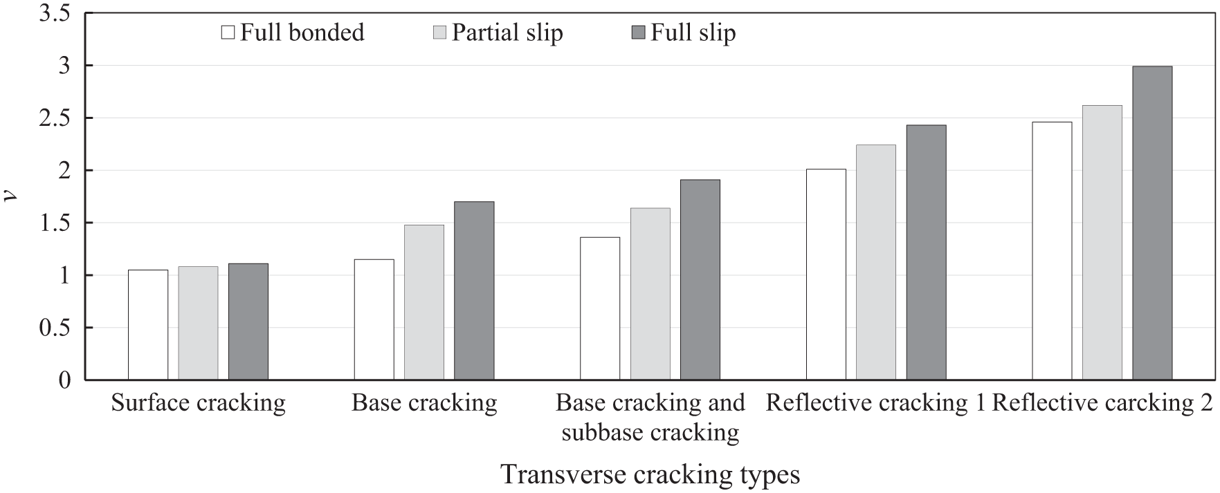
Values of v for transverse cracks in different bonding conditions.
The slope ratio from Figure 4 can be concluded as follows:
The slope ratio is between 1.05 and 1.11 when only the surface crack exists;
The slope ratio is between 1.15 and 1.7 when only the base crack exists;
The slope ratio is between 1.36 and 1.91 when the base crack and subbase crack exist simultaneously;
The slope ratio is between 2.01 and 2.43 when the surface crack and base crack exist simultaneously (Reflective cracking 1);
The slope ratio is between 2.46 and 2.99 when the surface crack, base crack, and subbase crack exist simultaneously (Reflective cracking 2).
It can be found that the base cracking and base cracking together with subbase cracking cannot be identified by the slope ratio because their values are coincident. In addition, there are no obvious coincidences between the values of the slope ratio for other types of cracks. In particular, the values of the slope ratio for both base cracking and base cracking together with subbase cracking range from 1.15 to 1.91. It can be found that there are no coincidences for the combined values and the slope ratio values of other types of cracks. Namely, surface cracking, “Reflective cracking 1,”“Reflective cracking 2,” and hidden cracking (base cracking, or base and subbase cracking simultaneously) can be identified by the slope ratio.
Field Application
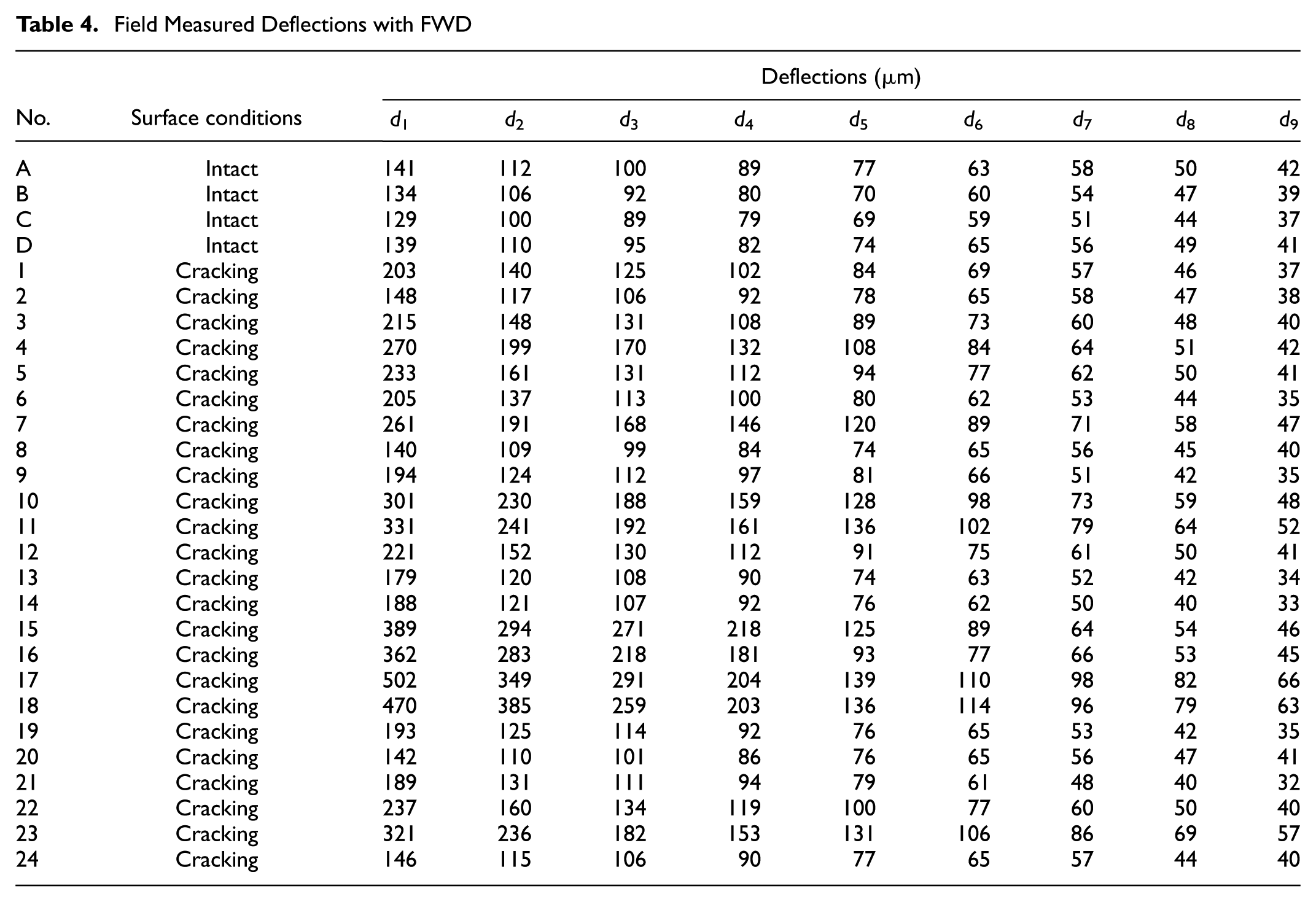
Deflections were measured on the evaluated road to verify the proposed indicator and criteria. Concretely, FWD testing was performed on four intact pavements and 24 transverse-cracked pavements, which are illustrated in Figure 7. All cracks were numbered. The final results are shown in Table 4. In addition, coring was conducted at the transverse cracks to identify the cracking types, two examples of which are presented in Figure 8.
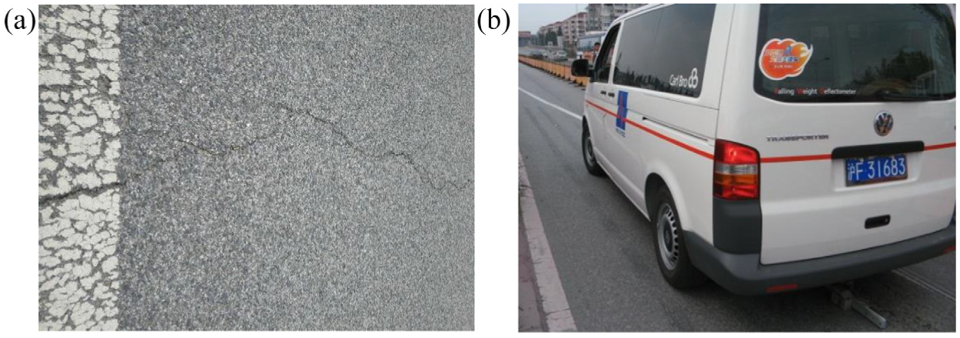
FWD testing performed on the evaluated road: (a) visible cracks on the surface and (b) FWD equipment.
Field Measured Deflections with FWD
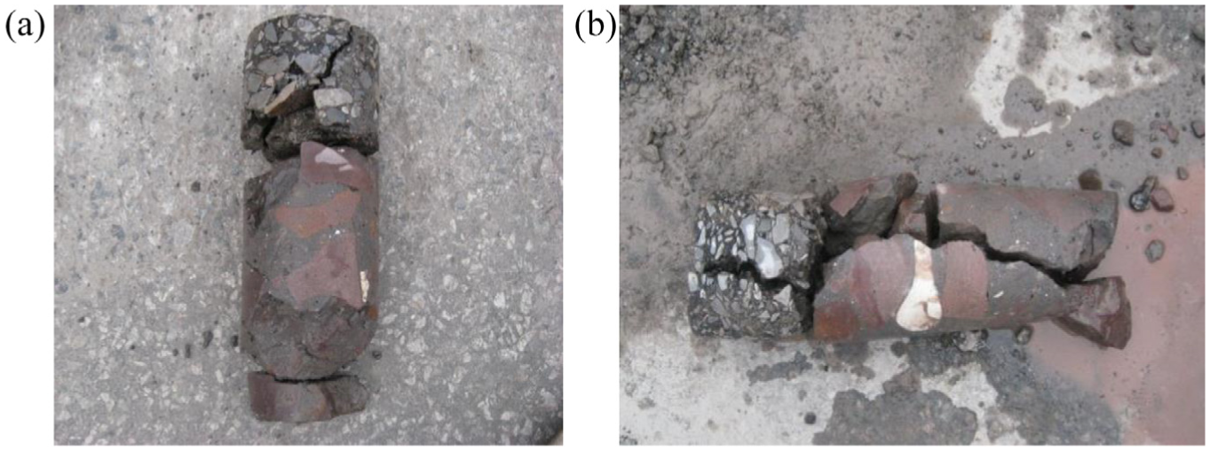
Coring conducted at the transverse crack: (a) the core of surface cracking and (b) the core of “Reflective cracking 1.”
The S1 of four intact pavements was calculated and the values were averaged as the reference value. Similarly, the S1 of 24 transverse-cracked pavements was also calculated. The slope ratio for 24 transverse-cracked pavements was determined with Equation 1 and the assessment was conducted according to the proposed criteria. The final evaluated results are shown in Table 5 together with the coring results.
Evaluated Results Compared with Coring Results
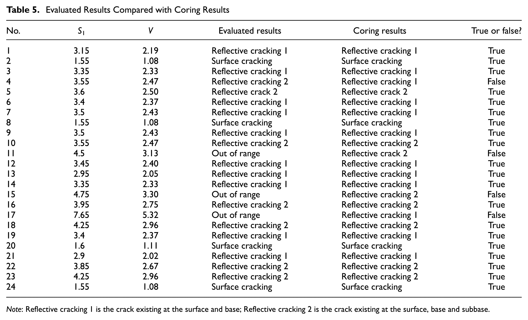
Note: Reflective cracking 1 is the crack existing at the surface and base; Reflective cracking 2 is the crack existing at the surface, base and subbase.
It can be observed from Table 5 that there are four misjudged results and the evaluation accuracy is 83.3%. This indicates that the proposed indictor and criteria can be applied to evaluate the transverse cracks of semi-rigid asphalt pavements. In fact, the misjudgments were induced by the suggested criteria values. For example, “Crack 17” is “Reflective cracking 1” while its value of v is more than the criteria value. This is because the criteria values are from the FE model analysis, which is developed with many hypotheses. According to the survey, there exists pumping near “Crack 17,” which makes the value of v increase significantly. Therefore, the proposed method should be utilized combined with other methods to evaluate the transverse crack. Besides, more investigations need to be conducted to improve the criteria values.
Conclusion
In this study, a 3D FE model was developed to simulate intact and transverse-cracked semi-rigid asphalt pavements under FWD loading. The model was validated by deflection basin data measured from in-situ FWD testing. The effect of crack types and crack width on the deflection basin was investigated for semi-rigid asphalt pavements under different interlayer contact conditions with the developed 3D FE models. Finally, the slope ratio to evaluate the transverse crack was proposed by correlation analysis and validated by the field application. The conclusions can be drawn as follows:
The existence of cracks will make the deflection basin steeper. For the same type of cracks, crack width slightly affects the deflection values when there are no interactions between adjacent cracking surfaces while the deflection values become obviously larger when surface-base interaction changes from “Full bonded” to “Full slip.”
The slope index (S1), the shape index (F2), and the area index (AREA) correlate well with transverse cracks, which can be utilized to evaluate the transverse cracks of semi-rigid asphalt pavements.
The surface cracking, “Reflective cracking 1” (surface and base cracking simultaneously), “Reflective cracking 2” (surface, base, and subbase cracking simultaneously), and the hidden cracking (base cracking, or base and subbase cracking simultaneously) can be identified by the slope ratio. However, the base cracking and base cracking together with subbase cracking cannot be identified by the slope ratio.
Field application indicates that the slope ratio can be used to evaluate the types of transverse cracks for semi-rigid asphalt pavements. It is suggested that the proposed method should be utilized combining with other methods to better evaluate the transverse cracks. In addition, more investigations need to be conducted to improve the evaluation criteria.
Footnotes
Acknowledgements
This work was sponsored by the National Natural Science Fund of China (ID: 51778477).
Author Contributions
The authors confirm contribution to the paper as follows: study conception and design, Lukuan Ma and Chongwei Huang; data collection, Jinsong Pang and Lukuan Ma; analysis and interpretation of results, Jinsong Pang and Lukuan Ma; draft manuscript preparation, Lukuan Ma and Min Li. All authors reviewed the results and approved the final version of the manuscript.
The Standing Committee on Pavement Condition Evaluation (AFD20) peer-reviewed this paper (19-04204).