
Abstract
In order to limit construction conflicts in bridges with precast, prestressed concrete girders, it is essential that designers are able to predict midspan girder camber with sufficient accuracy at key stages. This paper describes a study of the effectiveness of various strategies for improving camber predictions when compared with field-measured values from actual bridge girders produced in the southeastern United States. The study also incorporated concrete materials data from nearly 2000 girder production cycles among four regional producers, in addition to a laboratory study of mechanical and time-dependent properties of representative concrete mixtures. A standard incremental time-step analysis software was developed and utilized for the parametric study included in this work. For the girder production cycles monitored in this study, the use of regionally calibrated prediction models for material properties (concrete compressive strength, modulus of elasticity, creep, and shrinkage) resulted in the elimination of approximately 80% of the prediction error associated with current camber prediction practices within the region. As compared with a mean overprediction error of 68% for current design practice, implementation of calibrated prediction models reduced the mean overprediction to approximately 10%. The most effective prediction improvement techniques were determined to be reliance on expected rather than specified concrete compressive strength, the use of an appropriate aggregate correction factor for modulus of elasticity computations, and the use of an incremental time-step analysis method incorporating AASHTO Load and Resistance Factor Design (LRFD) or International Federation for Structural Concrete (fib) Model Code 2010 creep and shrinkage prediction equations.
Camber is defined as the deflection intentionally built into a structural element to improve appearance or to compensate for the deflection of the element under the effects of superimposed loads, shrinkage, and creep ( 1 ). Within the precast, prestressed concrete community, camber is regarded as the net upward deflection due to the eccentricity of the prestressing force. When properly predicted during the design phase, an appropriate amount of camber is desirable to avoid the perception of sagging under applied loads, and to ensure proper and timely alignment of adjacent bridge components ( 2 ).
Initial camber, or elastic camber, is the upward deflection induced upon transfer of the prestressing force into the concrete girder during fabrication of a bridge girder and is heavily dependent on the geometric properties of the girder, the stiffness of the constitutive materials, and the magnitude of the prestressing force ( 3 ). The term camber growth refers to the tendency of the initial camber to experience a net time-dependent increase as a result of various interrelated factors including maturing concrete properties, time-dependent deformations of concrete (creep and shrinkage), relaxation of the prestressing steel, and varying girder curing and storage conditions. Midspan camber in precast, prestressed bridge girders is regarded as among the beam deformations of greatest interest to bridge designers and thus, is a deflection essential to accurately predict during the girder design phase ( 3 ).
Previous work by others has demonstrated that the accuracy of design-phase predictions of midspan camber in precast, prestressed concrete elements may be improved by relying on best estimates of key concrete properties most likely to be observed during production rather than specified minimum values or unmodified design code prediction equations ( 4 – 8 ). In addition, various studies have explored other specialty strategies for improvement in camber prediction accuracy, including accounting for the effects of: (a) transient thermally-induced changes to girder deformations at the time of measurement ( 5 , 8 , 9 – 13 ); (b) the effect of construction practices ( 5 ); and (c) the use of refined analytical methods (e.g., incremental time-step methods) in lieu of more simplistic approximate methods (e.g., the Precast/Prestressed Concrete Institute [PCI] multiplier method) ( 4 – 6 , 8 , 14 – 20 ).
Despite the increased focus on various aspects of camber prediction in recent years, few studies have had sufficient scope to thoroughly investigate a wide range of strategies for camber prediction and the relative prediction accuracy of each. The objective of this paper is to summarize a comprehensive camber prediction study sponsored by the Alabama Department of Transportation (ALDOT) and provide practical recommendations to improve camber predictions for precast, prestressed concrete bridge girders ( 21 ).
Analytical Methods for Camber Prediction
Initial camber of precast, prestressed concrete girders is first observed at the time of transfer of the prestressing force into the girder during fabrication as a result of the superimposed effects of: (a) eccentricity of the prestressing force tending to induce negative flexure; and (b) the self-weight component of the girder tending to induce positive flexure. The magnitude of initial camber is computed using engineering beam theory relying on girder geometric properties, the magnitude and arrangement of prestress force, and material stiffness properties. Common methods for the computation of initial elastic camber include approaches relying on the superposition of simple cases or numerical application of flexural (moment-area) theorems ( 3 ). Most prestressed concrete commercial software relies on numerical application of flexural theorems for computation of initial camber due to the capability to include strand debonding and draped strand profiles ( 22 ).
In contrast to the relatively uniform methods employed to compute initial camber, the computation of time-dependent increases in girder camber (camber growth) is more varied and advanced. Depending on the complexity of a time-dependent camber prediction model, efforts to capture the interrelated nature of maturing concrete properties, time-dependent deformation of concrete (creep and shrinkage), relaxation of the prestressing steel, and varying girder curing and storage may or may not be included. The simplest widely adopted prediction method for camber growth is the PCI multiplier method as originally formulated by Martin ( 3 , 23 ). This method relies on characteristic assumptions of time-dependent girder behavior without independent consideration of concrete maturing material properties, creep, shrinkage, or steel relaxation. Most specialty software for prestressed concrete design uses the PCI multiplier method and allows for customization of multiplier coefficients to account for regional effects. In addition to the PCI multiplier method, American Concrete Institute (ACI) Committee 435 identifies two additional methods appropriate for computing long-term deflections in uncracked one-way prestressed concrete flexural members, each incorporating a series of cross-sectional analyses conducted at varying time steps throughout the life of the member ( 24 ). Among camber researchers, the more common method is an incremental time-step procedure which computes incremental changes to strain distributions, curvatures, and the prestressing force on a cross-sectional basis as a function of corresponding incremental changes to concrete strength, unit stiffness, shrinkage, and creep, and steel relaxation. While significantly more complex in application than the PCI multiplier method, various studies have endorsed the use of an incremental time-step method as a fundamentally sound approach for computing camber growth in precast, prestressed girders ( 4 , 6 , 9 ).
The Auburn University Highway Research Center (AUHRC) has refined an incremental time-step algorithm for this purpose and released as a freely available standalone software, ALCAMBER v1.0. This software resulted from the joint work of Johnson, Schrantz, Isbiliroglu, and Mante ( 13 , 15 , 21 , 25 ). It includes: (a) a graphical user interface; (b) databases of common PCI bulb-tee and AASHTO girder shapes, and prestressing strand sizes; (c) recommendations of various camber research studies for regional calibrations of input parameters; (d) incorporation of available ACI, AASHTO, and International Federation for Structural Concrete (fib) Model Code concrete material property models; (e) the capability to save and import data files; and (f) comprehensive and summary output reports. The software facilitates implementation of the incremental time-step algorithm for any varying combination of input parameters, from simple to complex. A sample ALCAMBER summary output report is shown in Figure 1.
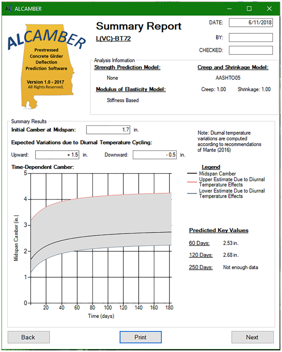
ALCAMBER v1.0 sample summary output report.
Experimental Methodology
Parametric studies were conducted to investigate the effect of input parameter sensitivity on the accuracy of camber predictions as compared with field measurements representing 22 normalweight precast, prestressed concrete girders produced at two regional production facilities. Varying input parameters were incorporated, ranging from the minimal information available to the initial girder designer to the best information gathered through intensive on-site data collection.
Design-Phase Prediction Input Parameters (Current Practice)
Typical initial predictions of girder camber are furnished by the bridge designer and represent the most approximate estimate of expected girder camber for a precast, prestressed bridge girder. Estimates of initial girder camber (at prestress transfer) rely on values of specified concrete compressive strength and code-based correlations relating compressive strength to modulus of elasticity. Time-dependent camber growth is then computed, based on either the approximate PCI multiplier method ( 3 ) or, at best, by incorporating unmodified code-prescribed time-dependent deformational models (concrete creep and shrinkage) into an incremental time-step approach with regionally-appropriate input parameters.
Regional Calibration Studies for Design Prediction Input Parameters
For each input parameter of interest to the camber prediction problem (e.g., concrete compressive strength, modulus of elasticity, concrete creep, concrete shrinkage, and concrete coefficient of thermal expansion), it was necessary to distinguish between the value specified by the initial girder designer and the value expected to occur during girder fabrication. The values expected to be observed during girder fabrication differ from those specified as a result of required margins of safety (in the case of concrete compressive strength) as well as the variability accompanying a manufacturing process that incorporates labor, equipment, and constituent materials within the study region.
In this study, candidate prediction models for those parameters most intrinsic to the camber prediction problem were generated through a series of in-lab and in-plant experimental efforts to quantify regional material properties and construction practices. While a brief summary of the analytical calibration techniques used to generate candidate prediction models for each parameter is included here for reference, the proposed prediction models may not have universal applicability to all girder production markets. Therefore, the focus of this paper remains on the effect of implementation of these best regionally calibrated prediction models on camber prediction accuracy. Comprehensive details of the regional calibrations summarized here are reported by Mante ( 21 ).
Concrete Compressive Strength
To facilitate camber predictions using an incremental time-step procedure, it is necessary to characterize the most likely values of key concrete material properties during fabrication and at each possible analysis age thereafter. For convenience in application, the approach utilized in this effort expressed the expected concrete strength at two key ages (prestress transfer and 28 days after concrete placement) as a function of the initial concrete strength specified by the design engineer. From there, ACI 209 concrete strength-growth expressions were implemented to extrapolate expected concrete strengths to other girder ages ( 26 ).
Historical concrete strength records representing nearly 5,000 precast, prestressed bridge girders were compiled from archived records of 1,917 girder concrete placement events performed by four producers in the Southeastern United States during the 6-year period preceding 2013. The data consisted of specified concrete strengths (at the time of prestress transfer and 28 days after placement), measured concrete strengths (at these same ages), and the chronological age of the girders at the time of prestress. Incorporating appropriate equation forms from ACI 214R, expected concrete strength prediction equations were generated and calibrated to the regional data set with calibration results shown in Figure 2 ( 27 ).
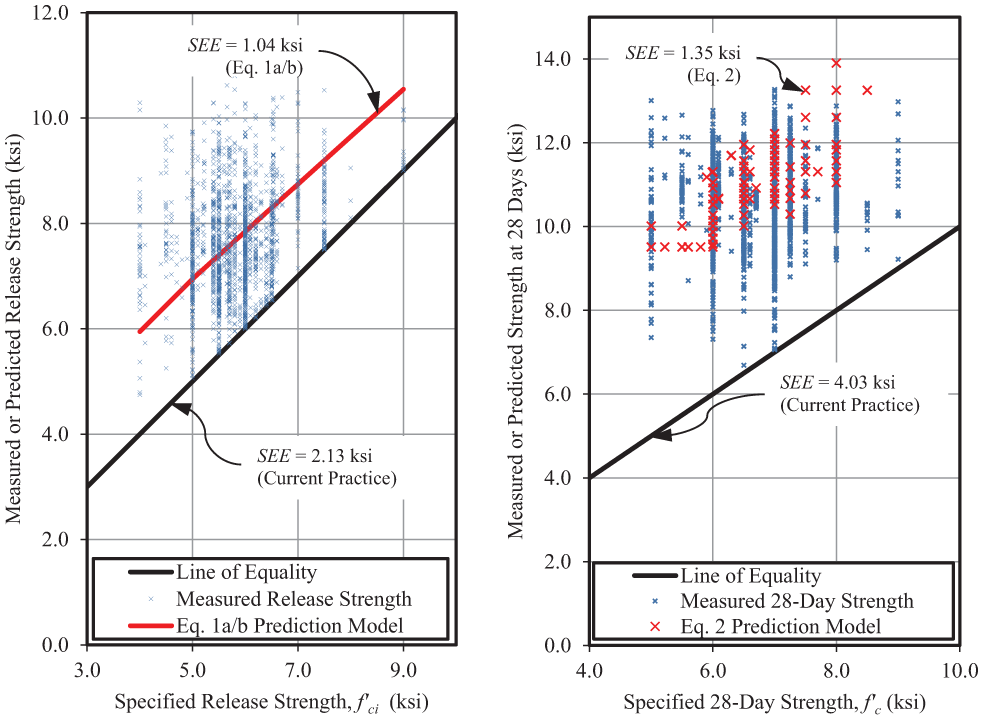
Concrete compressive strength at prestress transfer (left) and 28 days after placement (right) for calibrated strength prediction models. (1 ksi = 6.89 MPa).
To best fit regional data, the expected concrete strength at the time of prestress transfer,


where
Similarly, the expected concrete strength 28 days after concrete placement,

where
Equation 1 resulted from the historical data, using a calibration of a standard of quality control typical of regional precast, prestressed concrete producers (standard deviation = 1.05 ksi [7.24 MPa]) and substitution into existing provisions of ACI 214R (
27
). For measured 28-day compressive strengths, analysis of the historical data indicated better correlation with the specified strength at prestress transfer (
Concrete Modulus of Elasticity
Concrete material unit stiffness, as represented by modulus of elasticity, serves as the basis for deformational computations in structural elements. To facilitate camber predictions using an incremental time-step approach, the modulus of elasticity must be defined for all possible times of analysis. Until 2015, the modulus of elasticity was historically computed using AASHTO LRFD Bridge Design Specifications Equation 5.4.2.4-1 to correlate the concrete compressive strength at a time of interest to an expected modulus of elasticity ( 28 ):

where
Although reformulated in the 2015 AASHTO LRFD Interim Revision to better address lightweight concretes, Equation 3 as shown above remains valid for normalweight concretes with compressive strengths up to 10 ksi (69 MPa) because it provides similar results for these concretes ( 29 ). Calibration of Equation 3 to reflect appropriate regional concrete composition and material properties is possible through adjustment of the K1 parameter and can be accomplished by compiling concrete compressive strength and corresponding modulus of elasticity data. In this study, a data set was generated consisting of 148 data points each including time of measurement, aggregate type, curing method, unit weight, measured compressive strength, and measured modulus of elasticity. For normalweight concrete with limestone aggregates most typical of the study region, a calibrated value of K1 = 1.16 and 1.13 was appropriate for the time of prestress transfer and 28 days after concrete placement, respectively, as shown in Figure 3.
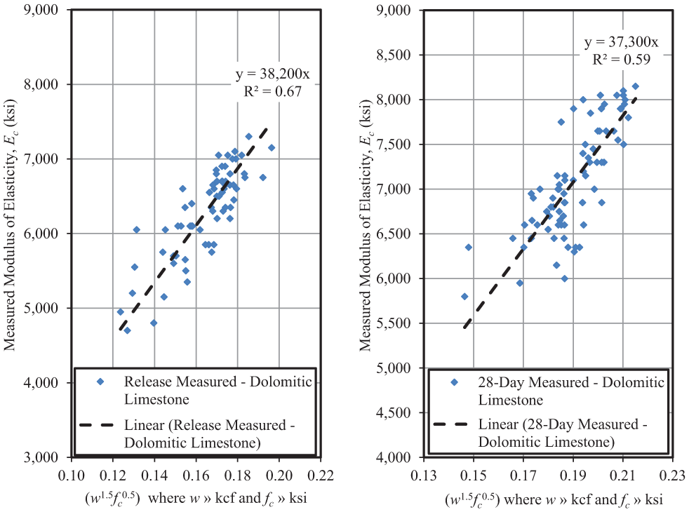
Calibration of AASHTO LRFD elastic modulus equation for typical regional aggregates at prestress transfer (left) and 28 days after placement (right). (1 ksi = 6.89 MPa; 1 kcf = 16,020 kg/m3).
The K1 factor at each age represents the best-fit slope coefficient in Figure 3 divided by the 33,000 coefficient of Equation 3. The time-dependent nature of the K1 calibration noted here has similarly been reported by others ( 8 , 30 ). While calibrations of the AASHTO LRFD prediction model are reported here to match regional design practice, calibrations to other proposed forms of modulus prediction equations were also explored and are available in Mante ( 21 ) (i.e., fib Model Code 2010, ACI 363 Method, and Noguchi et al. 2009 [ 31 , 32 , 33 ]).
Concrete Creep
Creep, the time-dependent increase of strain in hardened concrete subjected to a sustained stress, is the greatest contributing mechanism to camber growth and can result in an increase in magnitude of initial deformations by several times (
34
). The magnitude of creep is primarily influenced by mixture proportions, environmental effects, stress intensity, and construction methods (
35
). Laboratory evaluation of creep in concrete cylinders is performed in accordance with ASTM C512 (
36
) and is typically reported using either a creep coefficient,
Multiple prediction models (e.g., AASHTO 2014, ACI 209, and fib Model Code 2010) are available to designers of precast, prestressed concrete girders to predict a creep coefficient given input parameters representing expected mixture composition, environment, and construction timing. As an example, AASHTO LRFD Equation 5.4.2.3.2-1 can be used to compute the creep coefficient,

where
Six normal weight concrete mixtures were proportioned to represent mixtures typical of Alabama precast, prestressed work. These six mixtures included three regional coarse aggregates and three varying combinations of supplementary cementing materials (SCMs) at typical portland cement substitution percentages. Sampled cylindrical specimens were subjected to accelerated curing practices mimicking regional plant production schedules and tested in accordance with ASTM C512 for a period of 250 days ( 36 ).
Relying on measured values of relative humidity, specimen geometry, chronological age at loading, and compressive strength at loading, Equation 4 was calibrated to match creep behavior for each of 15 experimental iterations by means of a creep coefficient modification factor. Full details, including the use of an optimization technique proposed by Bazant and Panula as summarized in Appendix B of ACI 209.2R, are described by Mante ( 34 , 26 , 21 ). As a result of these calibration efforts, a creep coefficient modification factor of 0.80 provided the best fit for typical study region ternary mixtures consisting of Type III portland cement with fly ash and silica fume, while the unmodified Equation 4 (creep coefficient modification factor of 1.0) provided best agreement with all other mixture compositions included in this study. Calibration results for a typical dolomitic limestone aggregate concrete are shown in Figure 4 for the three creep prediction models included in this study. AASHTO LRFD permits use of any of these three models for use in predicting creep deformations ( 28 ). In this study, the best overall agreement between predicted and measured creep testing results was obtained by use of the calibrated fib Model Code 2010 model.
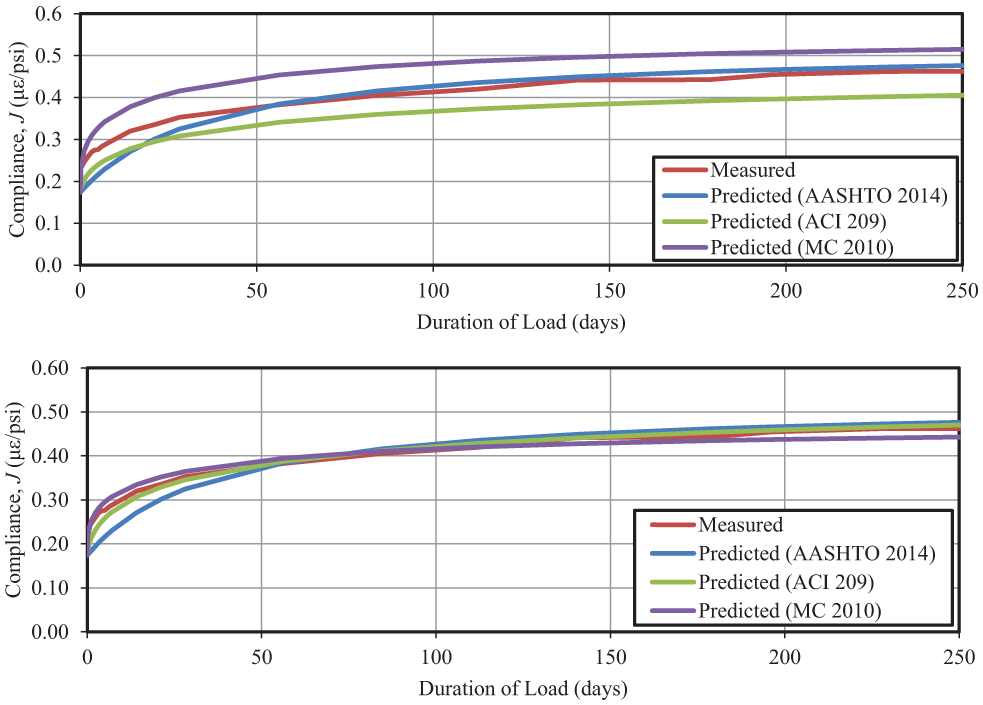
Comparison between experimental compliance results and unadjusted creep prediction models (top) and calibrated creep prediction models (bottom) for a typical dolomitic limestone concrete. (1 psi = 6.89 kPa).
Concrete Shrinkage
Shrinkage refers to the time-dependent decrease in volume of hardened concrete, independent of applied load ( 26 ). It is typically reported as a dimensionless strain and tested in accordance with ASTM C157 for prisms or alternatively obtained from ASTM C512 for creep testing of cylinders ( 38 , 39 ). Concrete shrinkage is affected by mixture proportions, environmental, and construction practices ( 35 ).
Multiple prediction models are available to designers of precast, prestressed concrete girders (e.g., AASHTO 2014, ACI 209, and fib Model Code 2010) to enable a designer to compute the expected shrinkage strain given input parameters representing expected mixture composition, environmental conditions, and construction timing. AASHTO LRFD Equation 5.4.2.3.3-1 is one of the options for computing shrinkage strain ( 28 ):

where
Companion testing of cylinders and prisms for concrete shrinkage was conducted with the creep testing program previously summarized. Sampled cylindrical and prism specimens were subjected to accelerated curing practices mimicking regional plant production schedules and then tested in accordance with ASTM C512 and ASTM C157, respectively ( 39 , 38 ). Relying on measured parameters characterizing environmental conditions, specimen geometry, chronological age of exposure, and compressive strength at loading, Equation 5 was used to compute expected shrinkage strains through the 250-day duration of testing for each concrete. An optimization of Equation 5 similar to that previously detailed for creep was performed for each experimental iteration and resulted in a proposed shrinkage modification factor for AASHTO LRFD of 0.80 for typical regional concrete mixtures incorporating Type III portland cement, slag cement, fly ash, or silica fume. Pre- and post-calibration results for a typical dolomitic limestone aggregate concrete are shown in Figure 5 for considered prediction models including AASHTO LRFD, ACI 209, and fib Model Code 2010.
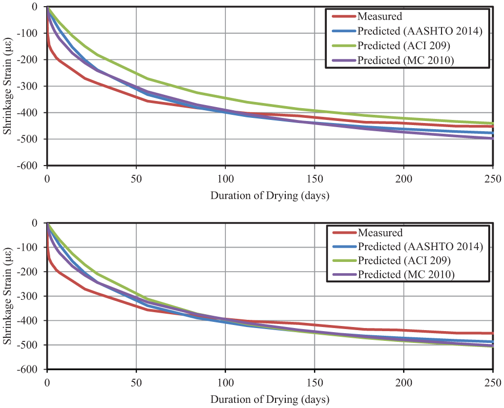
Comparison between experimental shrinkage results and unadjusted prediction models (top) and calibrated prediction models (bottom) for a typical dolomitic limestone testing iteration.
Concrete Coefficient of Thermal Expansion
Pre-erection girder camber is typically measured at various ages as the girder rests in storage at the production facility. Such measurements unavoidably reflect the effect of diurnal temperature fluctuations and varying solar exposure on girder deformations, which collectively tend to induce transient changes in cross-sectional strains, curvatures, and girder camber. Depending on the environmental conditions accompanying each measurement, theoretical values of girder camber can be artificially amplified, decreased, or remain unchanged by such affects. Mechanics-based temperature-correction procedures are well documented elsewhere ( 5 , 10 , 11 , 24 , 40 ). They allow researchers to adjust field measurements of girder camber to remove the varying effect of diurnal temperature fluctuations using the concrete coefficient of thermal expansion (CTE).
In this study, the deformational responses of three hardened bulb-tee girders subjected to diurnal temperature profiles during in-plant storage were continuously monitored for a period of approximately 24 hours. During this testing period, internal temperature sensors monitored concrete temperatures at 15 depths within the midspan cross section and four depths at another cross section. In addition, various metrics of girder deformation (four internal concrete strains at midspan and at another cross section, vertical deflections at three intermediate locations along each girder, and girder end rotations) were also monitored throughout each test as shown in Figure 6.
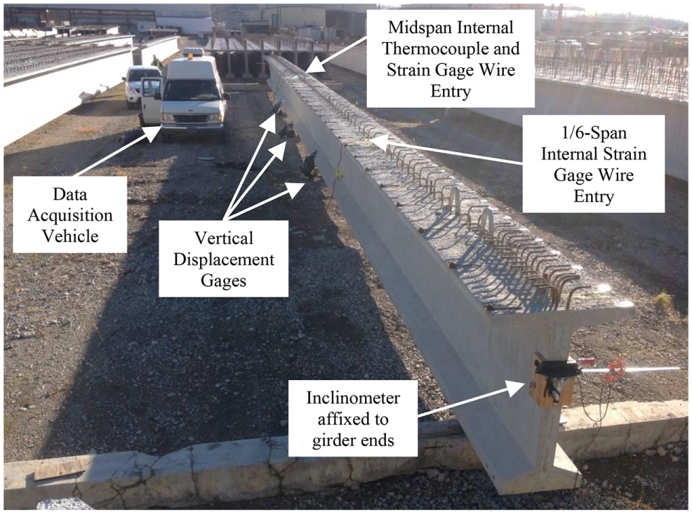
Testing of bulb-tee girder for calibration of concrete coefficient of thermal expansion to measured changes in strain, curvature, and deflection.
Relying on field measurements of girder internal temperature and associated girder deformations, it was possible to backcalculate an “effective” girder CTE resulting in the closest match between predicted girder deformations and measured deformations. For the concrete girders in unshaded outdoor storage monitored in this study, an “effective” CTE value between 7.2 and 7.5 µε/°F (13.0 and 13.5 µε/°C) provided best agreement between predicted and measured changes in strain as shown in Figure 7 for a typical testing iteration. The effective CTE value was then used to adjust all field measurements of girder camber to filter transient temperature effects.
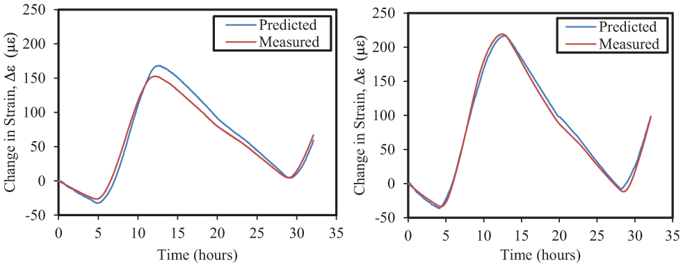
Diurnal concrete strain change within bulb-tee girders bottom flange (left) and top flange (right) for “effective” coefficient of thermal expansion = 7.5 µε/°F (13.5 µε/°C).
Field Data Collection
The primary objective of field data collection in this effort was to gather detailed data from actual girder production events to enable comparisons with trial camber predictions of varying thoroughness generated using the ALCAMBER v1.0 software. In-plant testing was conducted for nine girder production cycles, representing 22 ALDOT precast, prestressed concrete bridge girders produced at two facilities. In-plant testing efforts consisted of: (1) measurement of concrete material properties at key ages for various curing conditions (compressive strength according to ASTM C39 and modulus of elasticity according to ASTM C469 [ 41 , 42 ]); (2) instrumentation of selected girders with internal strain and temperature sensors at the midspan and one other cross section; and (3) measurements of girder camber at various girder ages using surveying equipment as shown in Figures 8, 9 and 10, respectively. For the in-plant testing, two distinct curing regimens were used for hardened property specimens as indicated in Figure 8: (a) standard curing of 28-day strength specimens; and (b) curing of specimens in a preheated lime bath to more accurately reflect strength development under field temperature and humidity conditions. Separate quality assurance specimens were prepared and tested by plant personnel in accordance with ALDOT specifications.
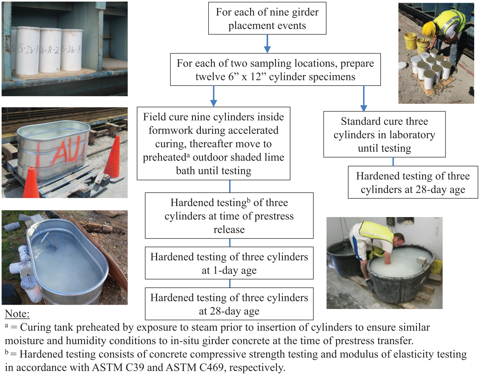
Summary of field data collection plan for concrete material testing.
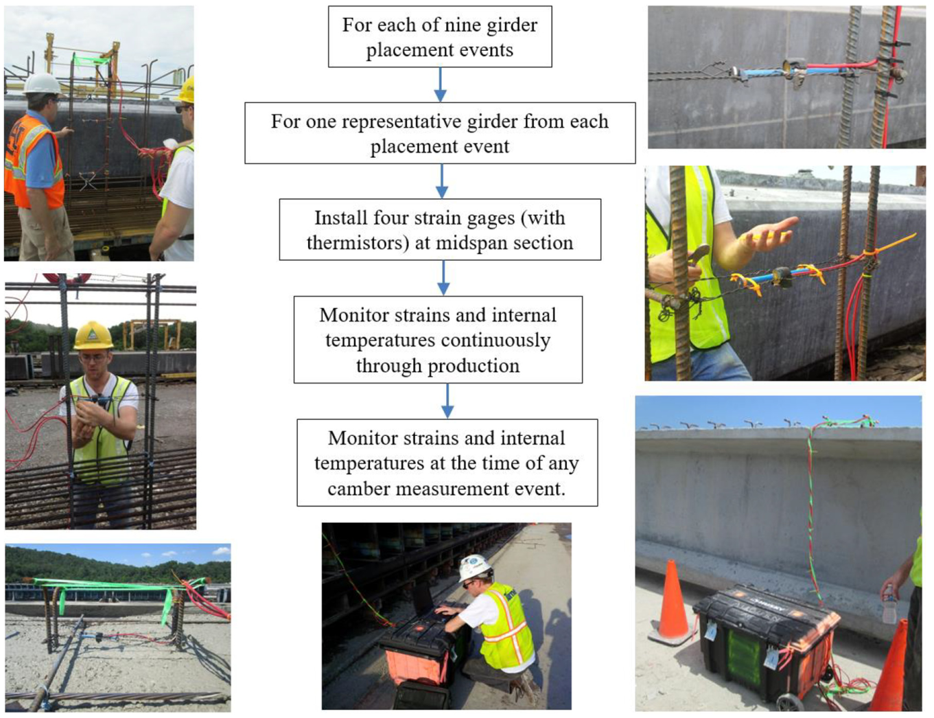
Summary of field data collection plan for measurement of girder internal strain and temperature.
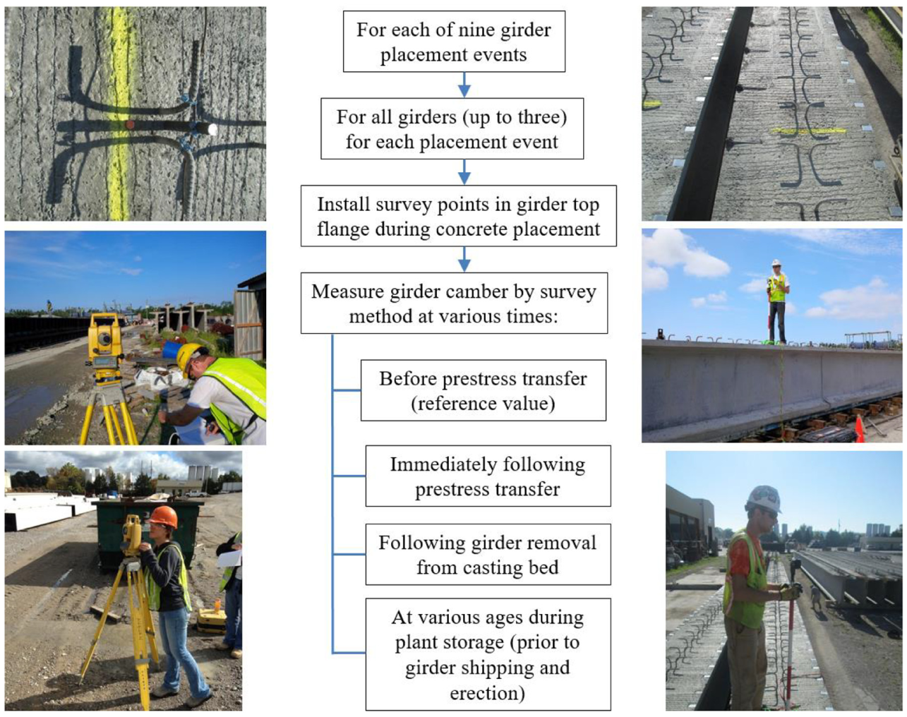
Summary of field data collection plan camber measurement at various girder ages.
To address transient variability in camber due to ambient effects, all girder camber measurements recorded in this study were temperature-corrected using a refinement of the flexural mechanics technique detailed by Johnson and the effective CTE described in a previous section ( 13 ). Camber was measured by comparing midspan displacement to displacements at the girder ends. Measurements were made immediately before and after any temporary changes in support conditions. Dunnage support locations were controlled to match final bearing locations.
Parametric Study
Analytical Procedure
Various combinations of input parameters were implemented within the incremental time-step analysis procedure of the ALCAMBER v1.0 software to generate predictions of initial and time-dependent changes to pre-erection girder camber for each of the nine in-plant girder production cycles. Three primary levels of input parameter detail were utilized in this study: (1) use of information available to the initial girder designer/specifier at the time of design; (2) use of information available to initial girder designer modified by the regional calibrations reported previously in this paper; and (3) use of concrete compressive strength and modulus of elasticity measured during in-plant monitoring of each production cycle. Notation representing the various camber prediction procedure permutations considered in this study is shown in Figure 11.
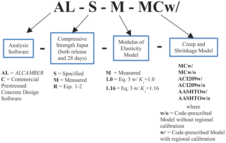
Notation for camber prediction procedure parametric combinations.
Comparison between prediction results and temperature-corrected field measurements of girder camber, strain, and curvature for each production cycle allowed for the assessment of the relative accuracy of each procedure as well as comment on the isolated and combined effects of selected parametric combinations. To compare the accuracy of predicted girder cambers to measured field behavior for each trial prediction procedure, percent difference was selected. This metric was used because it reflected whether a given prediction model tended to over- or underestimate the measured value and it facilitated appropriate summary statistics (mean and standard deviation of the percent difference) useful in assessing the average prediction procedure accuracy across the nine monitored production cycles. Percent difference as used herein was computed as
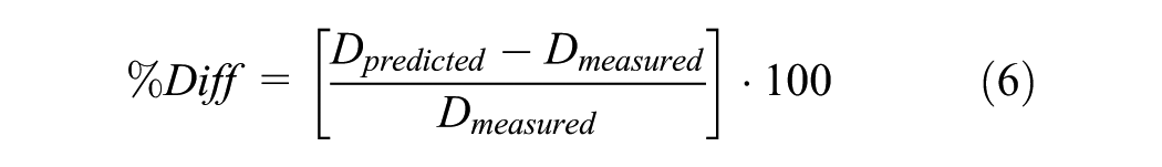
where
Results and Discussion
Parametric study results summarizing the effect of isolated variables on girder camber prediction accuracy are shown in Figure 12, with a mean (µ) and standard deviation (σ) reported for each prediction model combination. The mean represents the mean percent difference (prediction error) for a given combination of prediction techniques, while the standard deviation describes the dispersion of the prediction error for that combination across all ages of camber measurement.
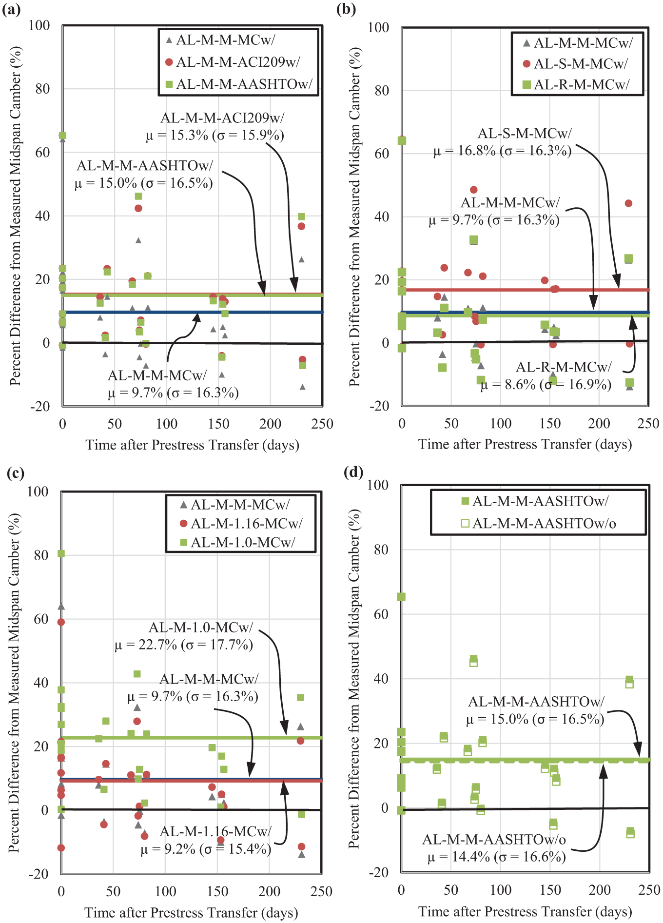
Comparisons between measured and predicted camber representing (a) best estimates from field-measured data, (b) varying concrete compressive strength inputs, (c) varying modulus of elasticity inputs, and (d) varying time-dependent inputs.
As expected and supported by previous literature, best predictions of girder camber resulted from the use of known input properties measured during on-site monitoring and time-dependent deformation models calibrated to typical regional mixtures by companion laboratory studies (4–8). For the production cycles monitored in this study, the most accurate predictions of girder camber resulted from the prediction procedure implementing the time-dependent deformational model of the fib Model Code 2010 (AL-M-M-MCw/) with an average camber prediction exceeding measured values by only +9.7%. Similar models implementing the calibrated ACI 209 and AASHTO LRFD time-dependent deformational models overestimated girder camber by +15.3% and +15.0%, respectively. These best estimates of girder camber (Figure 12a) served as comparison benchmarks for other trial camber prediction procedures relying on less complete information.
Figure 12b captures the isolated effect of using expected or measured concrete strength instead of specified concrete strength accompanied by the most accurate time-dependent model of the study, the regionally calibrated fib Model Code. As shown, the use of the calibrated prediction Equations 1 and 2 (AL-R-M-MCw/) generated predictions on the same order of accuracy as data measured on-site (μ =+8.6%), while use of the specified value (AL-S-M-MCw/) resulted in predictions with nearly double the prediction error (μ =+16.8%) as compared with best predictions. This indicates the improvement in prediction accuracy that is obtained by using the expected concrete compressive strength rather than the specified strength.
Figure 12c captures the isolated effect of varying inputs for concrete modulus of elasticity. The use of calibrated prediction Equation 3 (AL-M-1.16-MCw/) generated predictions on the same order of accuracy as measured on-site data (μ=+9.2%), reaffirming the validity of the regional calibrations generated in this study. The use of Equation 3 without an aggregate factor (AL-M-1.0-MCw/) resulted in predictions with 2.5 times the prediction error (μ=+22.7%) as compared with best predictions. This indicates the improvement in predication accuracy that can be obtained by using an appropriate aggregate correction factor.
Figure 12d explores the effect of calibration of the AASHTO LRFD time-dependent deformational model represented by Equations 4 and 5 independent of other input variations (e.g., compressive strength or modulus of elasticity). As shown, use of the calibration model (AL-M-M-AASHTOw/) resulted in insignificant changes in camber prediction accuracy when compared with the standard creep and shrinkage model (AL-M-M-AASHTOw/o) for the girder design iterations monitored in this study.
Parametric study results summarizing the combined effects of varying input parameter combinations on girder camber prediction accuracy are shown in Figure 13.
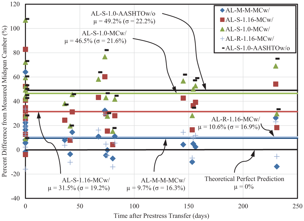
Comparison between measured and predicted camber for selected prediction procedures.
A candidate prediction model implementing the recommended regional calibrations of Equations 1-5 (AL-R-1.16-MCw/) resulted in an average camber prediction accuracy (μ =+10.6%) approximately equal to the best possible prediction model (AL-M-M-MCw/). For comparison, a metric of current design practice (reflecting material models not calibrated to regional results) is provided (AL-S-1.0-AASHTOw/o) and demonstrates that current design practice based only on specified concrete compressive strength tends to generate camber predictions that, on average, exceeded measured values by almost 50%, even with the use of an incremental time-step analysis procedure. In this study, the use of regionally calibrated material models or in-plant measured properties in lieu of current design practice reduced the average prediction error from +49.2% to the best possible value of +10.6%, representing a removal of nearly 80% of the prediction error associated with current design practice.
The use of commercial software (which relied on the PCI multiplier method) tended to overestimate initial girder camber (at prestress transfer) of +68.3% when material models not calibrated to regional results were used, reducing to +25.6% when the concrete material calibrations of Equations 1, 2, and 3 were used. Predictions of time-dependent camber within commercial software resulted in net overprediction of time-dependent camber at erection (assumed 60 days after prestress release) approaching +40% as compared with the best incremental time-step prediction (AL-M-M-MCw/) accuracy of approximately +10%.
Summary and Recommendations
In this study, use of regionally calibrated prediction models for material properties intrinsic to the camber prediction problem was able to eliminate nearly 80% of the girder camber prediction error associated with current design practice. For the nine normalweight girder production cycles monitored in this study, the use of calibrated prediction models to better predict expected concrete compressive strength, modulus of elasticity, creep, and shrinkage jointly resulted in a net overprediction of girder camber of only +10% as compared with the +50% to +68% overprediction typical of current design practices. The use of an incremental time-step analysis procedure, such as the one incorporated into ALCAMBER v1.0, is most appropriate for time-dependent predictions of girder camber in precast, prestressed concrete girders.
Designers of precast, prestressed concrete girders seeking to improve camber prediction accuracy should consider implementing the following strategies (in descending order of effectiveness):
Rely on the expected concrete compressive strength (as estimated by design experience, producer feedback, or regionally-calibrated model) rather than specified concrete compressive strength, particularly at time of prestress transfer;
Rely on a modulus of elasticity prediction equation that includes an appropriate aggregate correction factor (as estimated by design experience, producer feedback, or regionally-calibrated model);
Implement an incremental time-step analytical method that includes AASHTO LRFD or fib Model Code 2010 creep and shrinkage prediction equations and a reasonable estimate of girder age at erection; and
Pursue further refinements of the AASHTO creep and shrinkage prediction models to better match time-dependent deformational properties of regional concretes.
Footnotes
Acknowledgements
Material contained herein was obtained in connection with the research project titled Improving Camber Predictions for Precast, Prestressed Concrete Bridge Girders, conducted by AUHRC. Funding for this project was provided by ALDOT. The funding, cooperation, and assistance of many people from this organization are gratefully acknowledged. Additional organizational support provided by Forterra (Pelham, AL), and Gulf Coast Prestress (Pass Christian, MS and Jonesboro, GA) is gratefully acknowledged as are material donations in support of this effort by: CEMEX; BASF Corporation; Holcim; Elkem Materials; and the Abbvie PAF. Administrative and laboratory assistance from: J. Matthews; R. Nylen; E. Gross; J. Browne; D. Cartin; P. Warden; B. Wilson; and S. Smith are also gratefully acknowledged.
Author Contributions
The authors confirm contributions to the paper as follows—study conception and design: R.W. Barnes, A.K. Schindler, D.M. Mante; data collection: D.M. Mante, L. Isbiliroglu, A. Hofrichter; analysis and interpretation of results: D.M. Mante, L. Isbiliroglu, A. Hofrichter, R. W Barnes, A.K. Schindler; draft manuscript preparation: D. M. Mante, R.W. Barnes, A.K. Schindler. All authors reviewed the results and approved the final version of the manuscript.
The Standing Committee on Concrete Bridges (AFF30) peer-reviewed this paper (19-03878).
The contents of this paper reflect the views of the authors who are responsible for the facts and accuracy of the data presented. The contents do not necessary reflect the official views or policies of ALDOT.