
Abstract
Airport pavement structures experience heavy aircraft tire loading through a localized contact area. Distributed three-dimensionally and non-uniformly, tire-pavement contact stresses directly influence the near-surface behavior of flexible airfield pavements. The resulting high shear stress levels induced by aircraft tire loading may lead to instability through shoving or slippage cracking. As the tire turns during taxiing, the risk of near-surface damage is exacerbated. In this study, numerical modeling of an inverted pavement system and a conventional flexible pavement structure loaded with a single tire from the A-380 landing gear was developed. The analysis matrix included two tire-inflation pressures, two speeds, and rolling conditions that varied from free-rolling to two turning maneuvers. Two analysis approaches were performed: 1) use of traditional critical point strains, and 2) domain analysis, which characterizes bulk pavement behavior using multiaxial stresses and strains. The critical strains, which are used as inputs for airfield pavement design, changed negligibly under varying tire turning conditions despite the asymmetric contact stress distribution. On the other hand, domain analysis not only captured the asymmetric pavement behavior, but also identified that altering the tire movement from a free-rolling condition to turning could induce a significant increase in the potential damage.
In flexible airfield pavement design, two critical distresses are considered: asphalt fatigue cracking and subgrade rutting ( 1 ). These distresses are linked to strain responses at the bottom of the asphalt concrete (AC) layer and the top of the subgrade, respectively. Using transfer functions, pavement damage evolves over the prescribed design life. The output provides the number of loading repetitions to failure before structural capacity is reached; however, the accuracy of the prediction is limited by the scope of the data for the transfer functions. New tire designs, new pavement technologies, aircraft load and configurations, and other innovative solutions may not be appropriately considered in the current design approach. In a recent study on flexible highway pavements with truck tires, a change in the tire-inflation pressure revealed a minimal change in the critical strains ( 2 ). Therefore, without differences in strains, the same level of pavement damage would be reached by two distinct loading conditions.
High magnitudes of applied loads are transferred to the pavement from aircraft tires through tire-pavement contact. At this localized interface, three-dimensional (3D) and nonuniform contact stresses govern the response within the near-surface region. In particular, a fully loaded aircraft induces high levels of shear, typically within 50 to 100 mm from the surface during taxiing. Furthermore, the current airfield pavement design scheme inadequately accounts for potential near-surface damage, including shoving and slippage cracking. According to the Federal Aviation Administration (FAA) Advisory Circular 150/5380-6C, slippage cracks within flexible pavements arise because of high shear stresses imposed by braking or the turning maneuvers of aircraft tires. The combination of high shear tire-pavement contact stresses and low shear resistance (or the poor interfacial bond) of pavement materials may lead to slippage and the formation of crescent-moon-shaped cracks with ends pointing away from the traffic direction ( 3 ).
In 2002, a high-speed exit on a landing runway (4R-22L) at the Newark International Airport experienced slippage failures caused by high trafficking of airplanes, landing and traversing the runway during the summer months ( 4 ). With increased ambient temperature, AC deforms more severely and this directly impacts the shear resistance of the layer. Song and Garg found that increased aircraft tire-inflation pressure and high temperature conditions further exacerbated potential damage at the near-surface ( 5 ). Observations of slippage cracking at the Newark International Airport runway were verified by a recent instrumentation project (on the lead line from runway to high-speed exit) by Cook et al. ( 6 ). The authors reported that areas experiencing high repetitions of braking and turning exhibited interfacial delamination and rapid deterioration. Exceeding the AC shear strength at the near-surface region may pose a major safety concern. To reduce the risk of slippage at the near-surface, appropriate pavement and lift designs must be adequate to dissipate high shear forces ( 4 , 7 ). Therefore, it is imperative to understand the critical combination of loading and environmental conditions that affect near-surface damage.
Objective
The main objective of this research is to quantify the near-surface response of airfield pavements induced by aircraft tire turning conditions using advanced numerical modeling. The analysis included comparison of critical strains according to the FAA flexible pavement design procedure. In addition, domain analysis, a new post-processing method recently developed at the University of Illinois at Urbana-Champaign, was implemented to evaluate the 3D pavement responses. Recent implementations have revealed that domain analysis can adequately distinguish the influence of free-rolling tire-pavement contact stresses within the near-surface region and address the shortcomings of developing a failure criterion based on single-point strain responses.
Analysis Matrix
Tire-Pavement Contact Stresses under Turning Conditions
Tire-pavement contact stresses for a single tire of an A-380 aircraft landing gear were represented in 3D and non-uniformly distributed within a predefined contact area ( 8 – 11 ). Following the protocol previously reported by Hernandez and Al-Qadi, aircraft tire-pavement contact stresses under free-rolling conditions were generated ( 10 ). For the contact area, the tire width and length dimensions were assumed to be 320 and 560 mm, respectively. A total of five ribs were considered: two 70-mm outer ribs, one 90-mm middle rib, and two intermediate 45-mm ribs.
As the aircraft tire turns, the slip angle defines the difference between the actual direction of the rolling tire and the direction toward which the tire is pointing. Inherently, the maneuver results in a lateral shift of forces toward the inner edge of the turn. Therefore, contact stress distributions become asymmetric as an inherent result of the shift in loading. Utilizing the relationship found between contact stresses under various rolling conditions of a validated truck tire model ( 12 ), the turning ratios were generated. Figure 1 presents the influence of turning on the sample transverse contact stresses within the rib nearest to the point of turn.
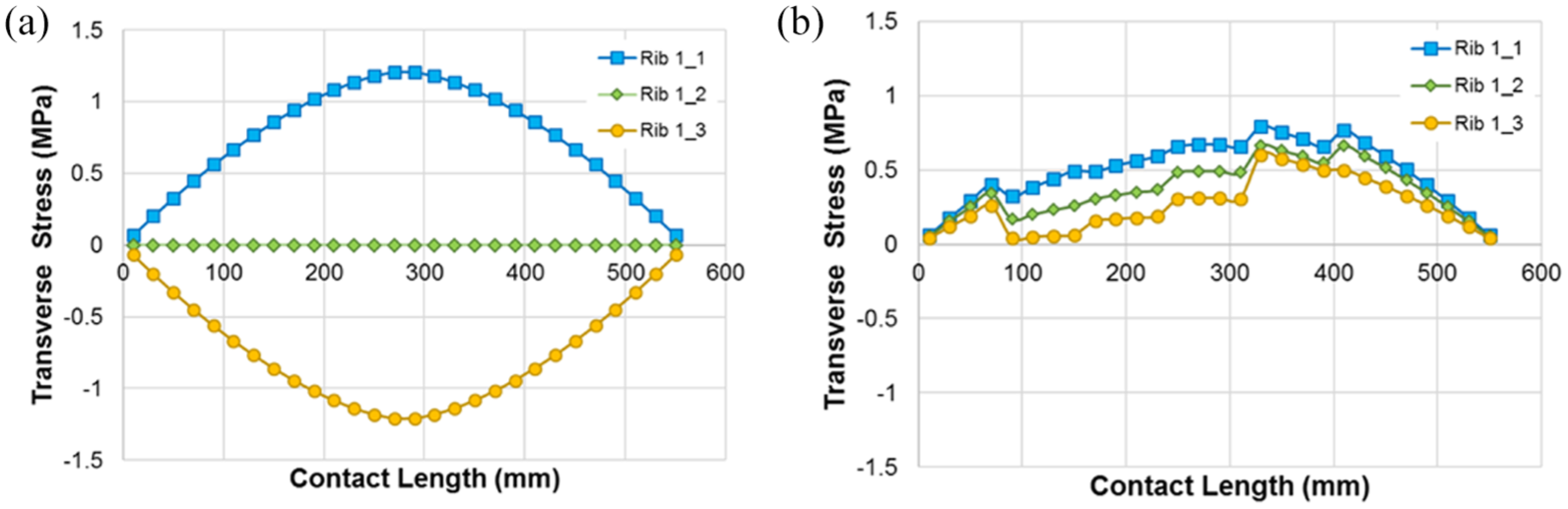
Sample transverse contact stresses: (a) free-rolling; and (b) turning maneuver.
It was imperative to ensure that the equilibrium was maintained during maneuvering; so that the summation of the resultant load within the footprint equates to the applied load. The following figures present the load distribution within each tire rib as the tire rolling condition is altered from free-rolling (FR) to turning (with slip angles of 2°, 4°, and 6°). Figure 2a illustrates the transfer of load from one rib to another, while achieving equilibrium. Not only is the lateral shift in the load evident along the vertical direction, but also along the transverse and longitudinal directions. Figures 2b and 2c reveal the lateral shift of the cumulative shear contact stresses toward the inner edge of turning. It is worth noting that the cumulative transverse contact stresses under FR are zero owing to symmetry. However, under the turning maneuver, the contact stresses increase asymmetrically as the slip angle increases.
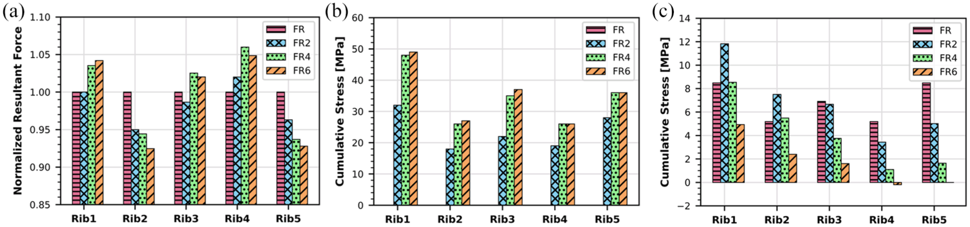
Overall influence of turning on aircraft tire-pavement contact stresses: (a) normalized resultant vertical load; (b) cumulative transverse contact stresses; and (c) cumulative longitudinal contact stresses.
In this study, 12 loading scenarios were used to consider an applied tire load of 262 kN with varying tire-inflation pressures, velocities, and slip angles. The nomenclature used to identify each load case is as follows:
Tire-inflation pressure (
Velocity (
Slip angle (
Given that the free-rolling condition is defined by a slip angle of 0°, the
Airfield Pavement Structures
A database of a continuously moving A-380 single tire load was generated and simulated over two airfield pavements structures. First, a National Airport Pavement Test Facility (NAPTF) flexible pavement (previously constructed in the high tire pressure [HTP] test area) consisted of 125 mm AC (P401), 200 mm crushed stone base (P209), 150 mm Econocrete (P306), and 810 mm uncrushed stone (P154) over subgrade ( 5 ). For consistency, the material designations used in this study follow FAA design guidelines ( 1 ). It is worth noting that the HTP section is prohibited from being constructed at airport facilities according to FAA regulations; however, it was built at NAPTF to allow high temperature testing. Secondly, from the recent NAPTF Construction Cycle 7 (CC7), the LFP4-N test section was considered to represent a conventional, flexible airfield pavement in which a select number of load cases were simulated onto the LFP4-N pavement structure ( 13 ). The LFP4-N pavement consisted of 200 mm AC and 1025 mm uncrushed stone base over subgrade.
The AC was assumed to be linear viscoelastic, while the supporting layers below the crushed stone base were characterized as being linear elastic. On the contrary, a nonlinear, isotropic, and stress-dependent material model was considered for the crushed stone base layer to account for the influence of high stress levels induced by the A-380 landing gear tire. It is noteworthy that for the LFP4-N test section, stress-dependent material properties for the subgrade, provided by FAA, were utilized within the pavement finite element (FE) model. Additionally, the developed FE model considered a continuously moving load, temperature profile within the AC layer, interface properties, and infinite boundary elements to represent far-field behavior ( 14 – 19 ). Details of the pavement model for the HTP test section, including the material characteristics and mesh sensitivity analysis can be found elsewhere ( 11 ). The same model preparation scheme was implemented in the LFP4-N pavement structure to ensure an optimum mesh configuration while balancing the computational effort and accuracy.
Results and Discussion
To determine the influence of the turning maneuver of an A-380 aircraft tire on pavement responses, two analysis approaches were completed. The first approach coincides with the conventional use of critical strains at predetermined locations: a tensile strain at the bottom of the AC and a vertical strain on top of the subgrade. According to FAA design methodology, these responses control bottom-up fatigue cracking and secondary rutting, respectively. In addition, a new post-processing technique, domain analysis, was used. The second approach accounts for the multiaxial stress and strain states within the pavement model via a single scalar parameter. Recent applications of domain analysis include truck and aircraft tire loading under FR conditions ( 2 , 20 ).
Point Responses
Congruent to traditional pavement analysis, maximum strains at critical locations were extracted from the pavement model output database, including, tensile strains within the surface and bottom regions of the AC layer, shear strains within each pavement layer, and vertical strains within each pavement layer. In particular, the tensile strain at the bottom of the AC (
Figure 3 illustrates the effect of the turning maneuver of an aircraft tire on critical strains. Note that each bar type represents a combination of pavement structure (HTP or LFP4-N), tire-inflation pressure, speed, and slip angle. For example,
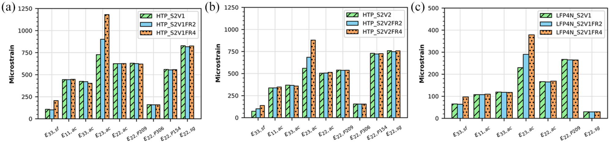
Critical strains at point locations of HTP and LFP4-N pavement simulations: (a) HTP with
Domain Analysis
In lieu of point strains, domain analysis quantifies the full influence of tire-pavement contact stresses within a loaded pavement model by considering multiaxial stresses and strains. Realistically, pavement damage is driven by the combined influence of shear and hydrostatic, whereas point strains describe pavement behavior at specific locations and directions.
The recently developed analysis scheme includes four main steps: 1) calculation of multiaxial stress and strain states; 2) discretization of the pavement to identify critical zones; 3) comparison of stress and strain states relative to the failure criteria; and 4) combination of the damage potential from selected critical regions to generate a unitless scalar called the cumulative ratio. Extensive details of domain analysis can be found elsewhere ( 2 ). A brief description of the new method follows.
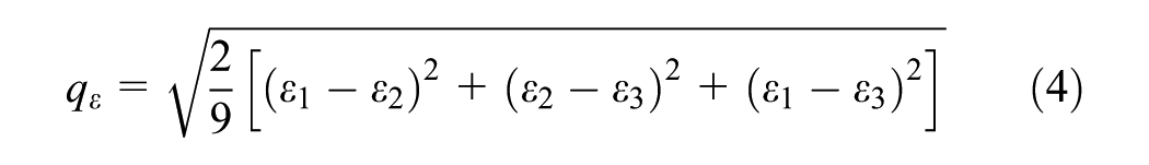
The initial steps of domain analysis involve determining the principal stresses and strains within a 3D subdomain of the pavement FE model by calculating the hydrostatic stress or strain, and the shear stress or strain indicator using the following equations:

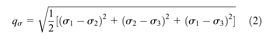
In which

In which
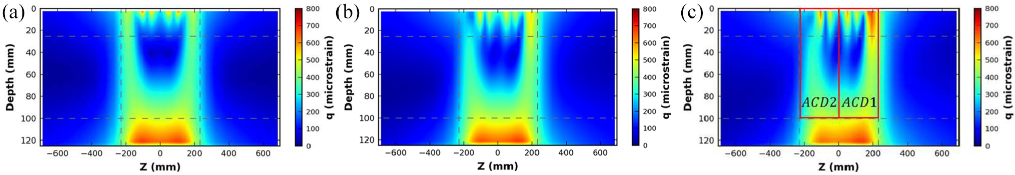
Partitioning the subdomain into nine zones along the vertical cross-section allows the user to define critical zones within each pavement layer, in which damage may be expected to nucleate. Zones 1 through 9 are designated starting from the top-left to the right, then downwards (Figure 4). On the one hand, the vertical zone limits are defined by the tire-pavement contact width and an additional 50 mm to the left and right sides of the tire. On the other hand, the horizontal limits require knowledge of pavements, specifically with respect to the location where near-surface distress typically arises, that is 50 to 100 mm from AC surface. It is worth noting that the contour plot presents the distribution of 3D pavement responses, in this case the mean strains, along the layer cross-section.
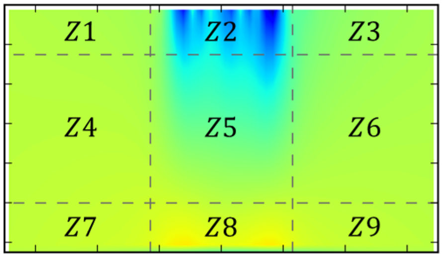
Zone partitioning along the layer depth.
The highest levels of shear and compression are observed within the near-surface region (
The next step in domain analysis relates the combined influence of the shear and hydrostatic stress to the failure criteria to penalize
To account for any geometric difference (e. g., increase in contact width and length induced by the loading condition), homogenizing factors are applied to normalize the cases along each orthogonal direction. Using the vector magnitude of each
In which
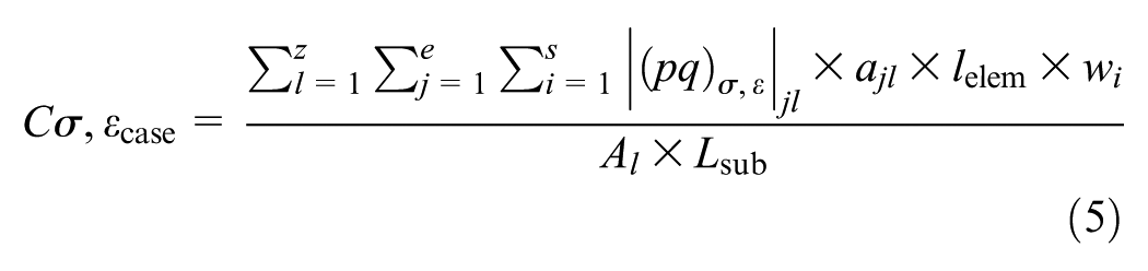
The cumulative ratio is calculated as follows:


In which
Domain Analysis Ratios
For each critical zone, the cumulative ratios,
HTP Test Section
Considering a high tire-inflation pressure (
Furthermore, the asymmetric behavior propagates deeper into the AC layer within the middle zone
Expanding the analysis into the 3D domain, the resulting
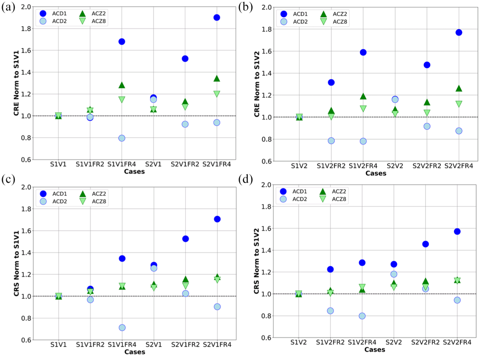
Domain analysis ratios for HTP pavement simulations: (a)
The corresponding
As the depth of analysis increased, the turning maneuver induced
CC7 LFP4-N Test Section
A select number of loading cases within the numerical matrix were applied to a conventional flexible pavement structure, LFP4-N, to understand the implications of tire turning maneuvers on a realistic airfield pavement. As anticipated, the near-surface region (
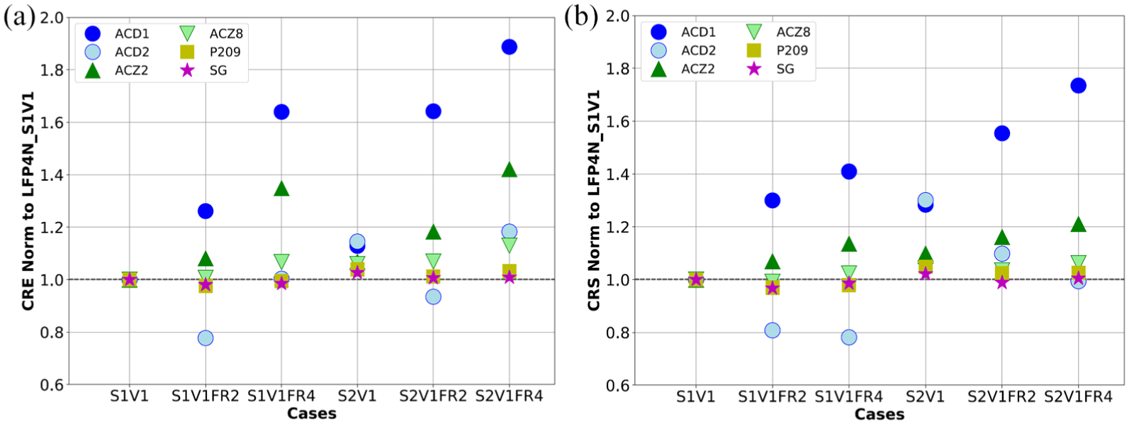
Domain analysis ratios for the LFP4-N pavement simulations (a)
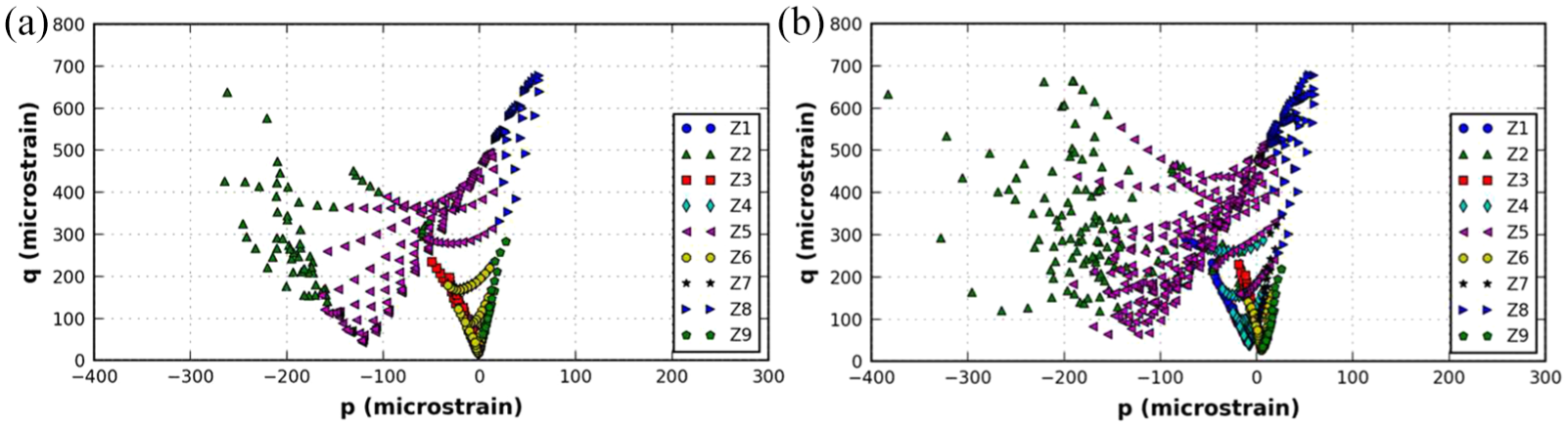
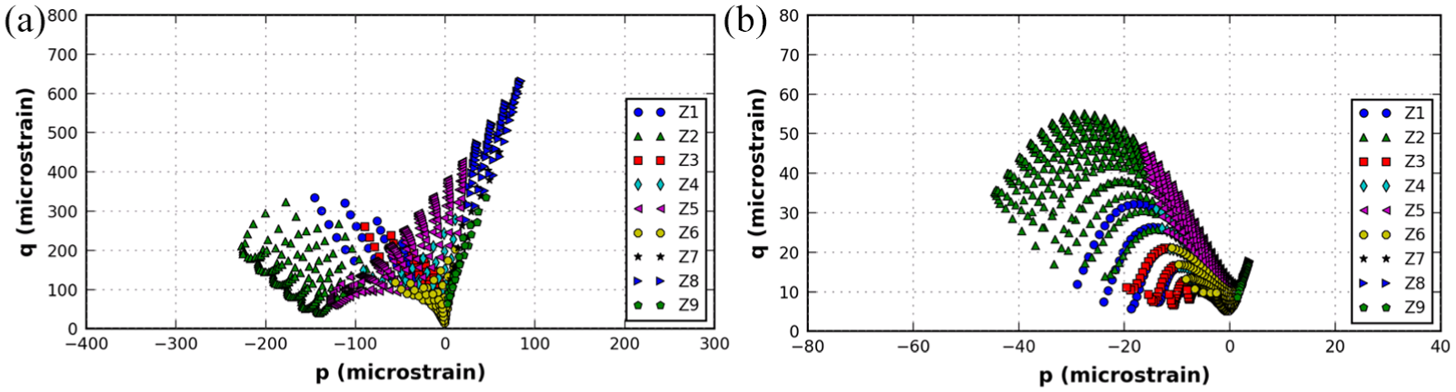
Although the ratios for the critical zones of the granular base layer and the subgrade remained close to unity in Figure 8, their multiaxial behavior significantly differed from the HTP pavement structure. Figure 9 illustrates the disparity in point cloud behavior of the stress-dependent granular base, directly underneath the AC layer, between the two pavement structures. Figure 9a illustrates the higher sensitivity to tension for the HTP section, whereas Figure 9b reveals the more significant combination of shear and compression for the LFP4-N section. The domain analysis provided a more in-depth investigation of pavement behavior using the
Summary and Conclusions
Bottom-up cracking within the AC layer and rutting within the subgrade layer govern airfield pavement design and analysis. Surface tensile and shear strains within the near-surface region of the AC layer, for inverted and conventional airfield flexible pavements, are highly affected by the turning maneuvers of aircraft tires. Given the current design protocol, any potential near-surface damage may not be quantified or analyzed. For instance, cases of slippage cracking, driven by high levels of near-surface shear, impose significant safety issues for an active airport. One of the major drawbacks of relying on single-point strains is that structural evaluation is narrowed down to represent bulk behavior via a specific location and direction.
Pavement damage generally nucleates within a given region of influence and not solely from a single point. Therefore, in lieu of point strains, near-surface damage warrants a more extensive analysis to quantify the full impact of tire-pavement contact stresses. Domain analysis, developed by the University of Illinois at Urbana-Champaign, characterizes the damage potential by accounting for multiaxial stresses and strains. One of the useful applications of domain analysis is quantifying damage potential at the near-surface, where tire-pavement contact stresses have the highest consequence.
The turning maneuvers of the A-380 tire did not change the total load applied onto the pavement structure. However, the distribution of the contact stresses changed significantly and had a direct implication on pavement responses. Domain analysis outputs, including the
Footnotes
Acknowledgements
This work was sponsored by the Airport Cooperative Research Program through a Graduate Research Award. The authors are indebted to Navneet Garg, Larry Goldstein, Dominique Pittenger, and Mary Sandy for their guidance and investment in this research. Special thanks are also given to Sarah Pauls for her help throughout the research program timeline. This study used the Extreme Science and Engineering Discovery Environment (XSEDE), which is supported by National Science Foundation grant number ACI-1548562.
Author Contributions
The authors confirm contribution to the paper as follows: study conception and design: AG and ILA-Q; data collection: AG; analysis and interpretation of results: AG and ILA-Q; draft manuscript preparation: AG and ILA-Q. Both authors reviewed the results and approved the final version of the manuscript.
The ACRP Selection Panel for the Graduate Research Award Program on Public-Sector Aviation Issues peer-reviewed this paper (19-06122).