
Abstract
The wide deployment of vehicle automation and communication systems (VACS) in the next decade is expected to influence traffic performance on freeways. Apart from safety and comfort, one of the goals is the alleviation of traffic congestion which is a major and challenging problem for modern societies. The paper investigates the combined use of two feedback control strategies utilizing VACS at different penetration rates, aiming to maximize throughput at bottleneck locations. The first control strategy employs mainstream traffic flow control using appropriate variable speed limits as an actuator. The second control strategy delivers appropriate lane-changing actions to selected connected vehicles using a feedback-feedforward control law. Investigations of the proposed integrated scheme have been conducted using a microscopic simulation model for a hypothetical freeway featuring a lane-drop bottleneck. The results demonstrate significant improvements even for low penetration rates of connected vehicles.
Freeway traffic congestion, typically initiated at bottleneck locations, is a major problem for modern societies, causing serious infrastructure degradation and underutilization especially during high-demand periods. Increased travel times, lower speeds, and extended congestion in the network, are only a few of the immediate consequences. An efficient way to mitigate this problem is the development and implementation of proper traffic control strategies.
Bottleneck locations can be freeway merge areas, areas with a particular infrastructure layout (such as lane drops, strong grade or curvature, tunnels or bridges, etc.), areas with specific traffic conditions (e.g., strong weaving of traffic streams) or areas with external capacity-reducing events (e.g., work-zones, incidents). If the arriving demand is greater than the bottleneck capacity, then the bottleneck is activated, that is, congestion is formed upstream of the bottleneck location. It should be emphasized, however, that, according to empirical investigations ( 1 ), capacity flow in conventional traffic is not reached simultaneously at all lanes. Thus, traffic breakdown may occur on one lane, while capacity reserves are still available on other lanes. This implies that the potentially achievable cross-lane capacity is not fully exploited. Naturally, once congestion appears on one lane, it spreads fast to the other lanes as well, as drivers on the affected lane attempt to escape the speed drop via lane changing. After congestion has occurred, retarded and different vehicle acceleration at the congestion head causes the so-called capacity drop phenomenon, which breeds a reduction in the mainstream flow of a freeway, while congestion is forming upstream of the bottleneck location.
In the near future, vehicle automation and communication systems (VACS) are expected to revolutionize the features and capabilities of individual vehicles ( 2 ). The new features can be exploited via recommending, supporting, or even executing appropriately designed traffic control tasks. Vehicles equipped with VACS may act both as sensors (providing information on traffic conditions) and as actuators, permitting the deployment of strategies like variable speed limits (VSL) ( 3 ) and lane-changing control (LCC) (4, 5). Note that while VSL control is also feasible by means of conventional control infrastructure, employing variable message signs (VMSs), LCC is not feasible with conventional means, because it calls for the possibility to communicate with a few individual vehicles, rather than with the whole vehicle population as by use of VMSs. Results from trials with cooperative vehicle-to-infrastructure systems, supported by the U.S. Federal Highway Administration, can be found in Hale et al. ( 6 ).
Two feedback control strategies are investigated in combination in this study, aiming at mitigating congestion at bottlenecks. Specifically, LCC is used to achieve appropriate lane assignment of vehicles upstream of the bottleneck so as to increase the bottleneck capacity. On the other hand, mainstream traffic flow control (MTFC) via VSL guarantees that the flow approaching the bottleneck location is not exceeding the overall (possibly increased) capacity of the bottleneck. To test and evaluate the effectiveness of these strategies, four different scenarios are considered and 10 replications are conducted for each scenario using a microscopic simulator for a lane-drop motorway infrastructure. To focus attention on the control methodologies employed, we assume full compliance of the connected vehicles and no communication delays with equipped vehicles. In the following, the detrimental effects of congestion at bottleneck locations are first discussed, then, the feedback control strategies for MTFC via VSL and for LCC are outlined. The simulation setup is presented together with a discussion of the produced results. Finally, some conclusions are drawn.
Motorway Bottleneck Activation
Consider a hypothetical freeway stretch featuring a lane-drop bottleneck, as in Figure 1, or any other kind of bottleneck mentioned above. As long as the arriving demand
Capacity drop at the congestion head: Bottleneck activation leads to a speed breakdown at the bottleneck location. As a result, limited, different, and retarded vehicle accelerations from lower (within the congestion) to higher speeds (downstream of the bottleneck), are deemed to lead to a capacity drop which breeds a reduction in the mainstream flow and consequently an active bottleneck outflow
Blocking of off-ramps: The congestion tail is covering ramps, as it moves upstream of the bottleneck location over several kilometers on the mainstream. As a result, the off-ramp flow drops as well, and vehicles bound for the off-ramps are trapped within the congestion, thus accelerating its spillback further upstream.
Note that the blocking of off-ramps effect is independent of the capacity drop effect and leads to an additional reduction of the freeway throughput, that is, it reflects an additional source of genuine infrastructure degradation ( 7 ).
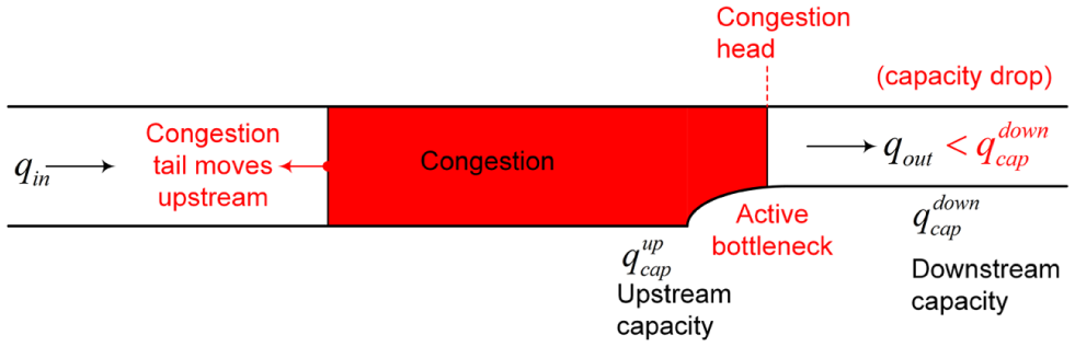
Representation of lane-drop bottleneck.
MTFC
VSL displayed on roadside or overhead VMS in response to prevailing traffic conditions is an increasingly popular freeway traffic control measure ( 7 ). One of the main targets of VSL is enhanced traffic safety as a result of the homogenization of speeds of individual vehicles and of the mean speeds of different freeway lanes which reduce the risk of accident ( 8 ). In this work, VSLs are applied to connected vehicles which may directly receive the value of the speed limit that is delivered by the control strategy, according to their current location in the network, and it is expected that, for sufficient penetration of equipped vehicles, this will be sufficient to impose the speed limit onto non-equipped vehicles as well; hence, no VMS gantries would be necessary.
The basic idea of MTFC is to enable the mainstream traffic flow approaching areas with particular infrastructure, for example, lane-drop or other bottlenecks, to take values ordered by an appropriate control strategy to establish optimal traffic conditions for any appearing demand (
9
). The MTFC concept used in this paper is illustrated in Figure 2. MTFC actions using VSL as an actuator are employed to regulate the mainstream flow upstream of the bottleneck location to be equal to the nominal capacity of the bottleneck
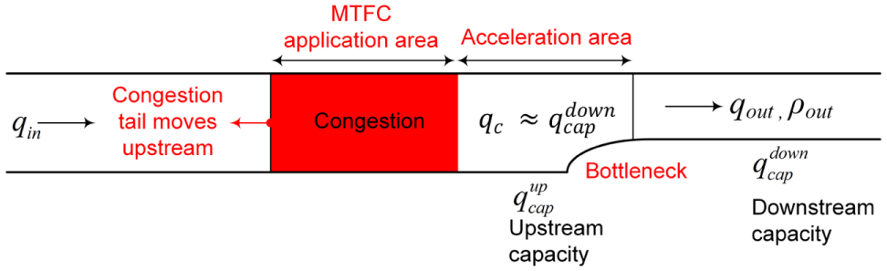
Representation of the MTFC concept.
MTFC Feedback Control Strategy
A proportional-integral (PI) feedback regulator is employed for MTFC, keeping the bottleneck density
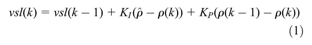
with k (=1,2,3,…) defined as the discrete time index. The time period T for updating decisions according to Equation 1 is 60s. Proportional and integral gains of the controller are denoted by
Some aspects of the practical implementation of VSL are then taken into account. VSL obtained from Equation 1 are rounded to the closest value of a set of predefined discrete values (e.g., 90, 80, 70, … km/h). Furthermore, the difference between two consecutive VSL values received by connected vehicles in a segment of the freeway is limited (e.g., to ± 10 km/h), so as to avoid abrupt speed changes. The difference between two VSL values at consecutive segments at the same control period is also limited (e.g., to 10 km/h), as often required in practice, to achieve a safe approach of vehicles within the safety areas.
LCC
LCC is a promising new strategy that can be exploited for traffic management (4, 5). The basic goal of LCC is to achieve a desired distribution of vehicles among the lanes in the immediate proximity of a bottleneck, so as to exploit the capacity of each and every lane, thus increasing the overall (cross-lane) capacity. To this end, a linear state-feedback control law, resulting from an appropriate linear-quadratic regulator problem formulation, is developed. The considered system under control comprises a number of interacting segment-lanes upstream of the bottleneck; while the feedback control law computes adequate lateral (lane-changing) flows for each segment-lane to be implemented by equipped vehicles, thus enabling an opportune, pre-specified distribution of traffic flow among the lanes. More specifically, the feedback control law uses real-time measurements (or estimates) of the state of the system, that is, of all segment-lane densities, and targets appropriate pre-specified set-points of lane-based traffic densities.
LCC Regulator Design
The problem of manipulating the lateral flows upstream of a bottleneck location to increase capacity and hence retard or avoid the creation of congestion, is formulated as a linear quadratic (LQ) optimal control problem. Based on a linear multi-lane traffic flow model proposed by Roncoli et al. (
4
), consider a multi-lane freeway stretch subdivided into
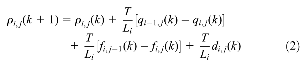
where:
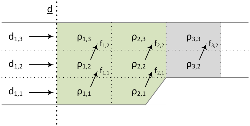
Model formulation.
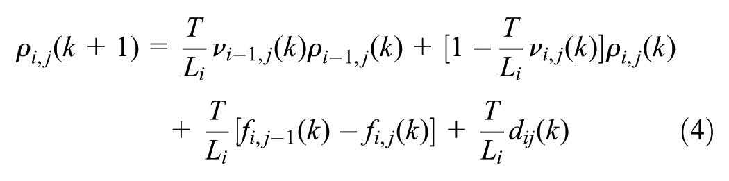
Depending on the network topology, some terms of Equation 2 may not be present for specific cells. Particularly, the inflow
Consider the well-known relationship:

Using Equation 3 and the conservation law in Equation 2, the following is obtained:
Treating speeds

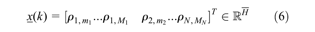
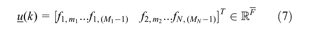
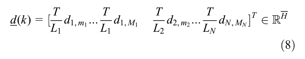
where the vectors of state, control, and external disturbances, respectively, are as follows:
Matrix
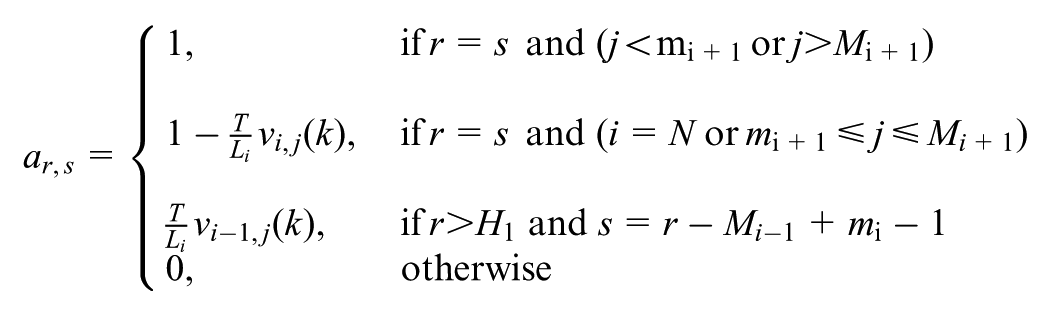
Matrix
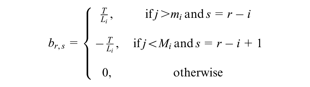
where
Assuming that the inflow arriving upstream of the bottleneck location is not exceeding the maximum capacity of the bottleneck (e.g., because of MTFC measures), and hence any formation of congestion can be avoided, the system can be treated as a linear time invariant (LTI) system. Specifically, in free flow conditions, it is assumed that speed

To achieve a desired distribution of vehicles among the lanes downstream of the lane-drop area (see gray area in Figure 3), a quadratic cost function is defined, which penalizes the difference between the cell densities at this area and pre-specified (constant) set-point values. A penalty term is also included, intended to maintained small control inputs, that is, small lateral flows (4, 5). The matrix form of the quadratic cost function reads:
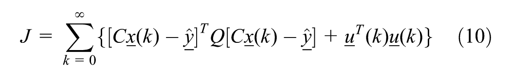
where:
the time horizon is infinite to enable a time-invariant feedback controller.
Note that
LCC Linear State Feedback-Feedforward Control Law
The solution to the formulated optimal control problem is given through a linear quadratic regulator (LQR) in the form of a linear state feedback-feedforward control law. To ensure a stabilizing feedback-feedforward control law, the system must be at least stabilizable and detectable; see Roncoli et al. (4, 5) for all the related details. The linear feedback-feedforward control law is given by:

where:


Note that the feedback gain matrix


where
The LCC law delivers “macroscopic” lane-changing flows for each cell. These lateral flows are translated to corresponding vehicle numbers that should change lane in each cell, and related messages are submitted to a corresponding number of equipped vehicles. Note that the control design model is only used for deriving the LCC feedback law, which is robust, that is, similarly efficient for changing speed values (corresponding to different “parameter” values in the control design model). Thus, although these assumptions of course do not hold true in a microscopic simulation model, the investigations reported in the following verify and demonstrate the effectiveness of the strategy with the controller being robust enough.
Simulation Investigations
Network Description
A hypothetical freeway stretch featuring a lane-drop bottleneck is considered in this paper for investigating the integrated use of the two feedback control strategies. Four scenarios are defined: no-control scenario, variable speed limits scenario, lane changing control scenario, and integrated control scenario. The freeway stretch illustrated in Figure 4 consists of 10 segments each of 0.5 km, resulting in a total length of 5.0 km. The biggest part of the network features three lanes starting from the entrance until reaching 4.0 km of freeway where the right-most lane (lane 1) drops, after which the last km has two lanes. Lane 2 is the middle lane and lane 3 is the left lane of the network (fast lane). When no VSL values are applied, the nominal speed limit is 100 km/h for all sections except for the two consecutive segments upstream of the bottleneck where the speed limit is 80 km/h.
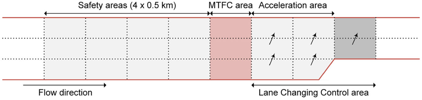
Freeway stretch used in simulations with the corresponding strategies.
Configuration of the Microscopic Model
The infrastructure layout for the investigation of the proposed strategies was developed and tested using an Aimsun Microscopic Simulator ( 11 ). AIMSUN includes AAPI and microSDK tools, which allows the replacement of the default models used by the simulator. The MTFC and the LCC strategies were implemented using the AAPI tool; while the microSDK tool was used to overwrite Aimsun’s default behavioral models.
The MTFC strategy utilizes density measurements aggregated over lanes for the lane-drop area and produces as an output the VSL values to be applied in the MTFC application area by all equipped vehicles in that area. Full compliance is assumed. The LCC strategy utilizes segment-lane density measurements for all cells in the controlled area as well as measurements of the external demand per lane to produce as an output the lateral flows to be implemented by a corresponding number of equipped vehicles within each segment-lane. In case of low penetration rates it may be necessary to use all equipped vehicles within a segment-lane, while in high penetration rates it may be enough to use just some of them which are picked randomly. Note that some ordered lane changes may not materialize, because they would violate some safety conditions set by the simulator. This leads factually to a limited “compliance” with the LCC commands, whose impact, however, is largely rejected because of the feedback nature of the controller. In all cases, non-equipped vehicles are allowed to change lanes as usual, and their actions are just a disturbance for the LCC controller, which is, however, rejected because of the feedback nature of the regulator used.
Aimsun uses the Gipps car following model ( 12 ) to represent the movement of vehicles, however, this model does not reproduce the capacity drop phenomena in critical regimes ( 13 ). For this reason, it was replaced with the intelligent driver model (IDM) car-following model ( 14 ), which reflects significant aspects of the traffic flow dynamics and features crash-free collective dynamics ( 15 ). In relation to lateral movements, Aimsun uses the Gipps lane changing model ( 16 ). The main limitation of this model is that it cannot capture realistically the merging behavior in a critical flow regime ( 17 ), and therefore it is complemented at critical merging locations (i.e., bottleneck area) with the addition of some heuristic rules ( 18 ) while for the rest of the freeway the original Gipps model is used. Ten replications are conducted for each scenario for a simulation horizon of 60 minutes. Each replication has the same average demand profile and the same mean values for all vehicle-related parameters. For each scenario, one replication close to the average of the 10 replications is selected for presentation in the following sections. The traffic demand profile for one of the replications is depicted in Figure 5. It can be observed that the demand is increasing for about 10 minutes, reaching values ( ~ 4,200 veh/h) well above the capacity of the bottleneck (3,600 veh/h). The demand remains high for about 15 minutes and then it is decreasing and staying at low values so as to allow for free flowing conditions at the end of the simulation horizon for all scenarios considered and, as a result, allow also the comparison of performance indexes between different scenarios.
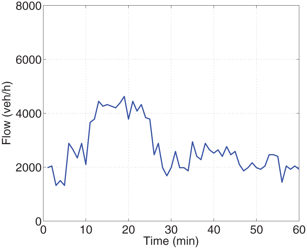
Traffic demand profile.
Simulation Results
No-Control Scenario
In the no-control scenario congestion starts at
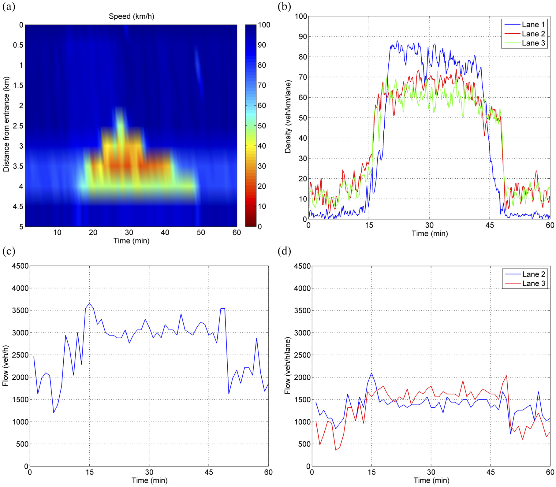
No-control scenario: (a) speed contour plot; (b) per lane density trajectories; (c) total outflow trajectory; and (d) per lane outflow trajectories at the lane-drop area.
Variable Speed Limits Scenario
The main goal of MTFC is to regulate the mainstream flow upstream of the bottleneck, that is, at the MTFC application area indicated in Figure 4, to maximize throughput. The penetration rate of connected vehicles that receive and apply VSL values is initially set to 20%. The speed contour plot resulting from MTFC application in the present investigation is presented in Figure 7a. All actions are delivered by the PI controller (Equation 1) every 60 seconds with a set-point equal to the critical density of 25 veh/km/lane, for which capacity flow is reached at the no-control scenario. Minimum and maximum values of VSL are set to 20 km/h and 100 km/h, respectively. No MTFC action is necessary up to
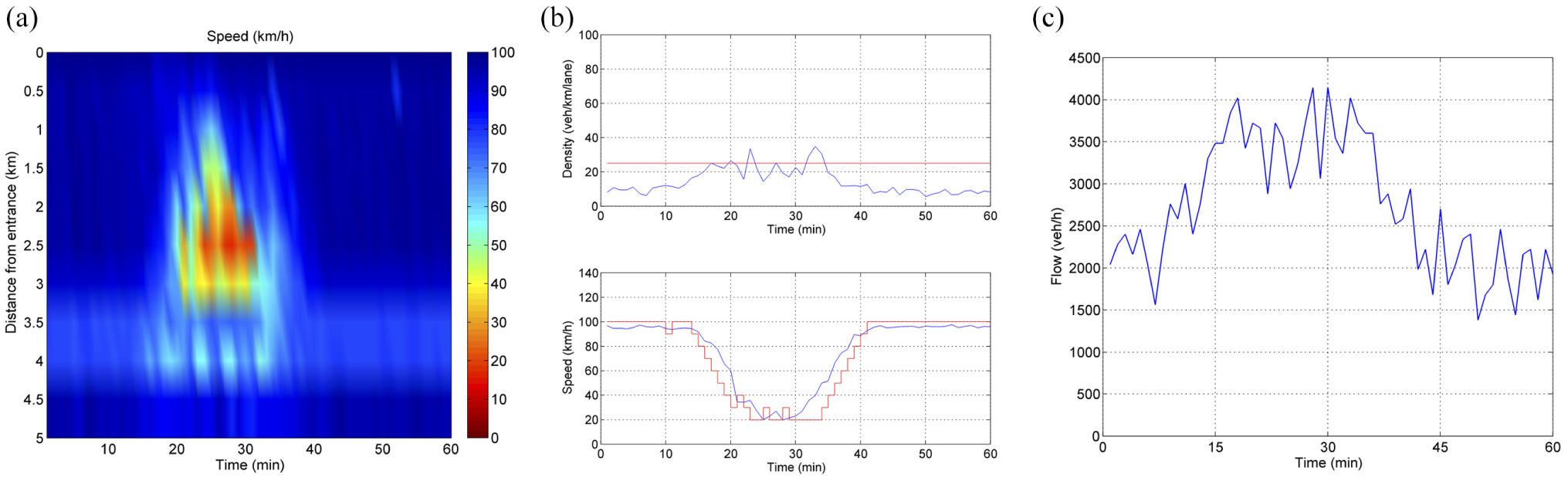
VSL scenario: (a) speed contour plot; (b) density measurements (blue line) at the bottleneck area (lane-drop area) with the corresponding critical density value (red line) and speed measurements at the MTFC application area with the corresponding speed limits (red line); and (c) total outflow trajectory at the lane-drop area.
As demonstrated in Figure 8, higher penetration rates of connected vehicles result in greater improvement of the average TTT value, approaching the value that corresponds to the case of VSL values displayed on VMS gantries, which corresponds to 100% penetration.
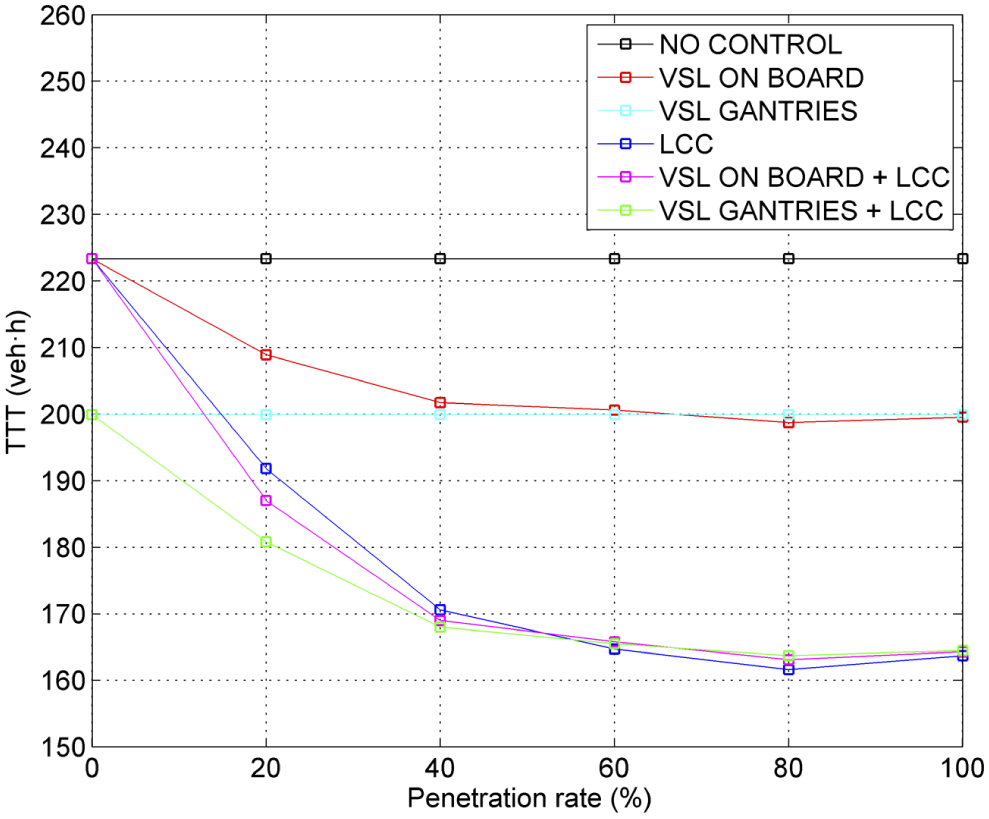
Average TTT per penetration rate of connected vehicles for the no-control case and control cases.
LCC Scenario
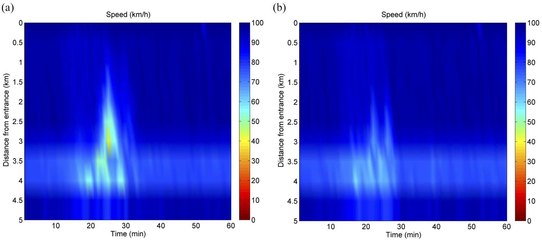
In this scenario, the goal of the controller is to achieve a density distribution at the area downstream of the lane drop that allows the full exploitation of capacity of each lane. This is done by delivering appropriate lateral flows by the linear feedback-feedforward control law (Equation 16) every 10 seconds. Speed contour plots resulting from the application of LCC in the present investigation are provided in Figure 9. The set-points used are 28 veh/km/lane for lane 2 and 33 veh/km/lane for lane 3 downstream of the lane-drop area.
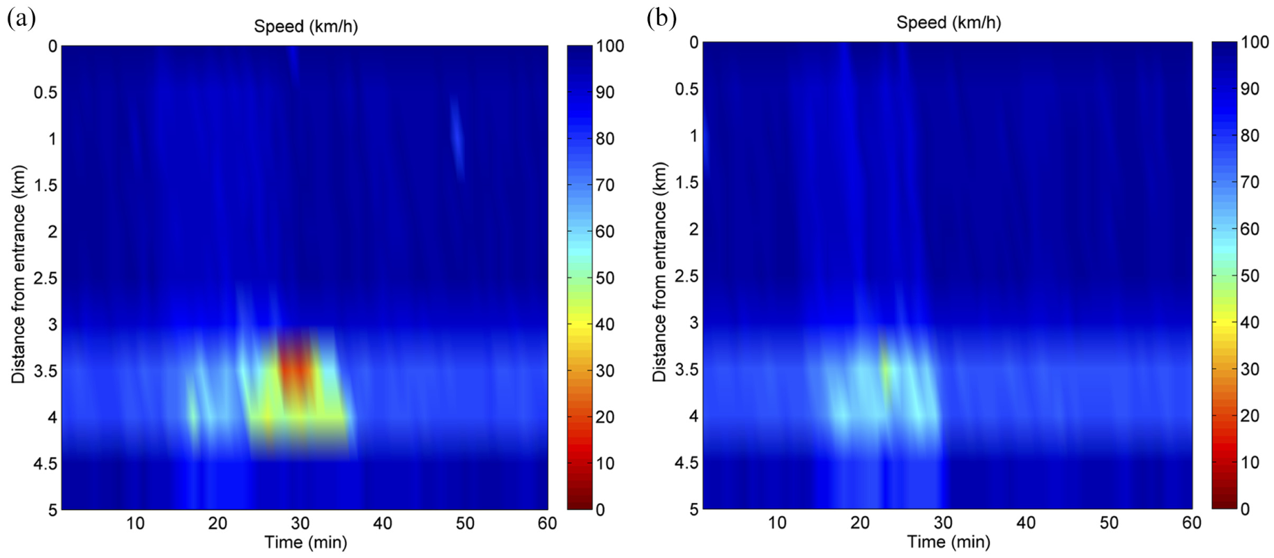
LCC scenario: speed contour plots for (a) 20% and (b) 80% of connected vehicles.
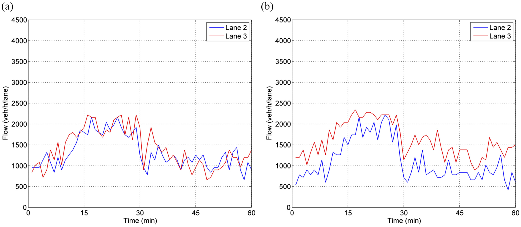
For a penetration rate of connected vehicles equal to 20% it can be seen from Figure 10a (when also compared with Figure 6d) that a higher outflow is achieved for lane 3 and that both lane 2 and lane 3 have a capacity around 2,100 veh/h which is maintained for about 8 minutes. However, the lateral flows ordered by LCC cannot be fully realized and the goal of the controller is not achieved for lane 3 (see Figure 11a). Congestion is then created because of further increasing demand, a capacity drop appears, and spillback of the congestion covers almost 1 km upstream of the lane drop area. Nevertheless, a 14.6% improvement of the average TTT is obtained compared with the no-control case. As observed in Figure 8, the achieved improvement in TTT increases for higher penetration rates reaching 27%.
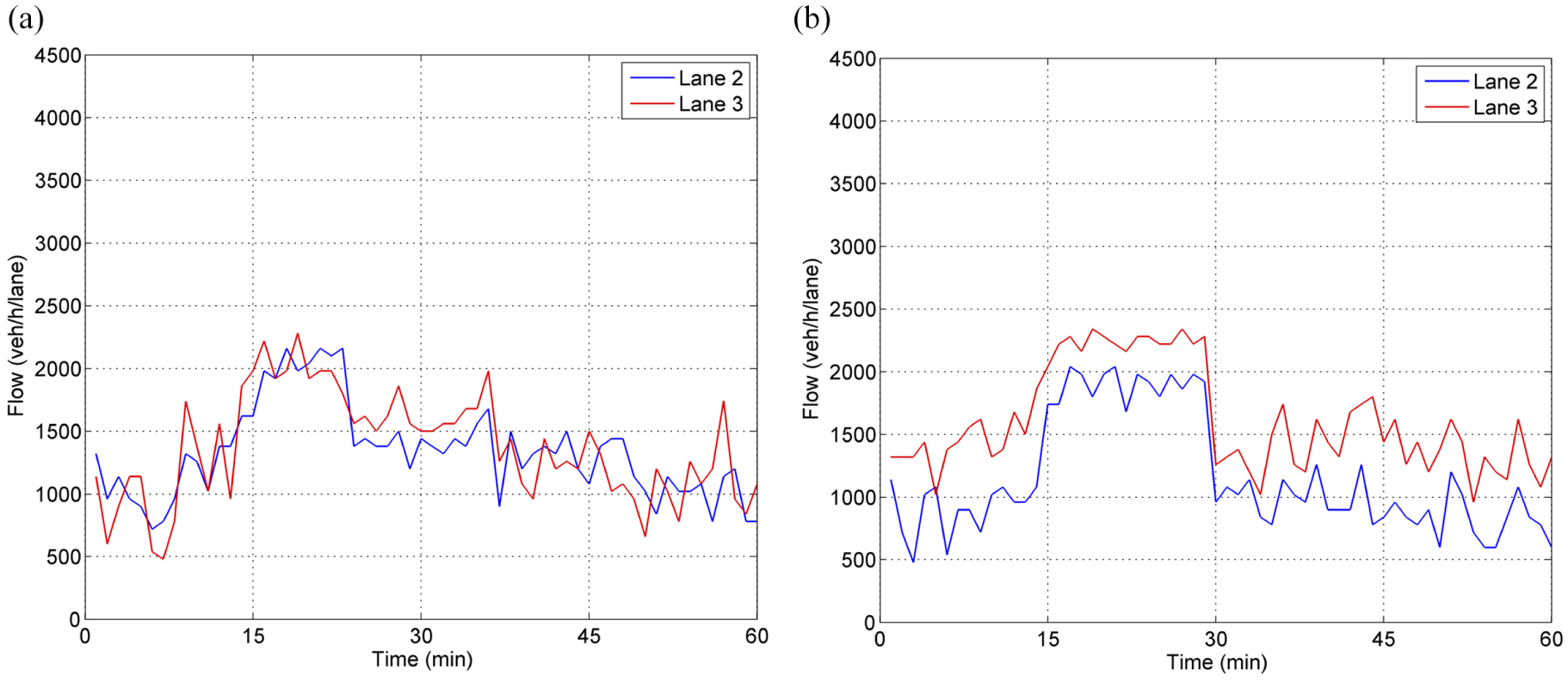
LCC scenario: per lane outflow trajectories at the bottleneck area (lane-drop area) for (a) 20% and (b) 80% of connected vehicles.
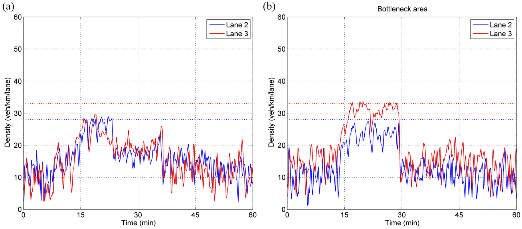
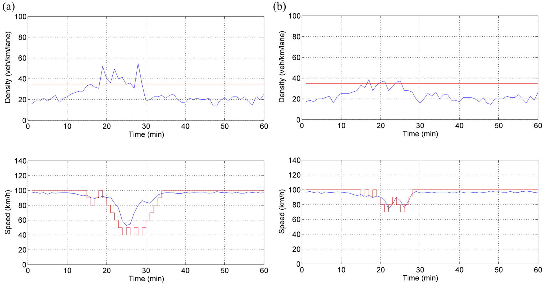
LCC scenario: per lane density trajectories (continuous lines) and corresponding set-points (dotted lines) downstream of the bottleneck area (lane-drop area) for (a) 20% and (b) 80% of connected vehicles.
For a penetration rate of connected vehicles equal to 80%, it can be observed (Figure 10b) that even higher outflow values can be achieved for lane 3. This is because the lateral flows ordered by LCC can be realized, and the goal of the controller is virtually achieved for a long period of time (see also Figure 11b). No congestion is created because of higher capacity values. The flow drop observed at
Integrated Control Scenario
In this case, MTFC is applied in addition to LCC to ensure that no congestion is created at the bottleneck and that the increased capacity because of LCC actions is maintained for longer periods of time. Speed contour plots are provided in Figure 12. Because of the increased capacity, higher set-points (35 veh/km/lane) are used in Equation 1 for the density values. For a penetration rate of connected vehicles equal to 20%, there is an increased improvement compared with both previous non-integrated scenarios. As observed in Figure 13a, VSL actions are still strong, without however reaching the minimum admissible value of 20 km/h. For a penetration rate of connected vehicles equal to 80%, VSL actions are moderate (Figure 13b) and TTT values are virtually equal to the ones obtained for the corresponding LCC scenario (see Figure 8). Figure 14a demonstrates that for a penetration rate of 20% the increased capacity achieved for lane 3 is maintained for a longer period of time compared with the non-integrated (LCC only) scenario (see also Figure 10a). For a penetration rate of 80% the capacity values achieved (Figure 14b) are similar to the non-integrated LCC scenario (Figure 10b).
Integrated control scenario: speed contour plots for (a) 20% and (b) 80% of connected vehicles.
Integrated control scenario: density measurements (blue line) at the bottleneck area (lane-drop area) with the corresponding critical density value (red line) and speed measurements at the MTFC application area with the corresponding speed limits (red line) for (a) 20% and (b) 80% of connected vehicles.
Integrated control scenario: per lane outflow trajectories at the bottleneck area for (a) 20% and (b) 80% of connected vehicles.
Conclusion
This paper presented the combined deployment and evaluation of previously proposed control strategies, namely MTFC via VSL and LCC, using a microscopic simulation model for a lane-drop infrastructure. VSL, even for low penetration rates, has proved successful in avoiding capacity drop. LCC is able to achieve an appropriate lane assignment of vehicles upstream of the bottleneck and as a result to increase capacity. For low penetration rates of connected vehicles, the integrated use of the two strategies is demonstrated to be highly beneficial. The reported results were obtained assuming full compliance and no communication delays. In the frame of the EU H2020 project INFRAMIX (https://www.inframix.eu/), the authors plan to investigate issues related to partial relaxation of such assumptions, utilizing more realistic models for connected and automated vehicles, related communications, and so forth, for some more bottleneck types and infrastructure layouts. Within the same project, it is also planned to test some aspects of the presented concepts in real field tests.
Footnotes
Acknowledgements
The research leading to these results has received funding partially from the European Research Council under the European Union’s Seventh Framework Programme (FP/2007-2013) / ERC Grant Agreement no. 321132, project TRAMAN21, and partially from the European Union’s Horizon 2020 research and innovation program under grant agreement no. 723016, project INFRAMIX. The authors thank all partners within INFRAMIX for their cooperation and valuable contributions.
Author Contributions
The authors confirm contribution to the paper as follows: study conception and design: IP, MP; data collection and analysis: VM, DIS; interpretation of results: VM, IP; draft manuscript preparation: VM, IP, MP. All authors reviewed the results and approved the final version of the manuscript.
The Standing Committee on Freeway Operations (AHB20) peer-reviewed this paper (19-03865).
The opinions expressed in this paper are those of the authors. The Innovation and Networks Executive Agency (INEA) is not responsible for any use that may be made of the information contained in this paper.