
Abstract
3D printed cement composites with and without carbon nanofiber (CNF) and microfiber (CF) reinforcement within the cement ink were evaluated at seven days and compared with their traditionally cast counterparts. A liquid lubrication layer at the extrusion nozzle was noted. The reinforcement type influenced the formation of the extruded filament, with underextrusion seen during 3D printing with the CNF cement ink while sudden discontinuation of extrusion was experienced during 3D printing with the CF cement ink. No noticeable interfacial region between printed filaments was observed in the 3D printed cement composites, with the exception of air cavities between printed filaments of the composite fabricated with the CNF cement ink. Lower compressive strengths were seen in the direction orthogonal to the print path for the 3D printed composites compared with the cast composites. The addition of CFs within the cement ink reduced this strength difference and led to strain softening in the post peak behavior.
3D printing is a process by which structures are built layer-by-layer, progressively adding material (filaments) to create a three-dimensional object from a digital file via robotic placement. It has lately received significant attention in the construction industry ( 1 – 8 ), specifically using cementitious material as the ink. Manufacturing via 3D printing provides greater design flexibility compared with traditional casting techniques and is expected to reduce construction time by eliminating the need for formwork and molds, decreasing waste, and increasing productivity ( 2 , 3 , 5 , 7 – 9 ). A review of the state-of-the-art of 3D printing with concrete can be found in Wangler et al. ( 8 ). In the transportation sector, it has the potential for new approaches to road and bridge repair, reducing traffic delays and minimizing disruption, as well as the design of new bridges and structures (e.g., tunnels, retaining wall, and bus shelters) with architectures that harmoniously blend into the urban environment and are not currently possible with traditional construction methods.
Cementitious materials have to fulfill certain requirements to be suitable as ink for 3D printing (cement ink): the cement ink needs to be flowable and sufficiently extrudable to be able to pass through a 3D printing nozzle while also having buildability to be able to hold its intended shape and not deform under the weight of successive layers. Meanwhile, the cement ink must have sufficient time before set (open time) to be able to be placed before the material hardens, and the hardened printed material must have sufficient qualities to be durable over the lifespan of its intended use ( 8 , 10 – 16 ).
Considering that cement-based materials need reinforcement to improve their load-carrying capacity and the practical difficulty of using traditional steel reinforcement (rebar) in conjunction with 3D printing, the use of discrete, short fiber reinforcements (e.g., microfibers) within the cement ink has been proposed as an alternative ( 8 , 16 – 26 ). An extensive discussion regarding reinforcement of 3D printed concrete can be found in Asprone et al. ( 19 ). Short fiber reinforcements have been shown to improve the strength and ductility of 3D printed cementitious materials and to be effective at mitigating shrinkage ( 1 , 16 , 18 , 20 – 24 , 27 – 33 ). Most of the focus to date has been on steel, glass, and polymeric microfibers. However, 3D printing of cement-based materials with carbon nano and microfibers has received little attention, despite the demonstrated benefits of carbon fibers in traditional cast concrete, including strength improvements and smart property capabilities ( 34 – 40 ). In addition, while the mechanical behavior of short fiber reinforced 3D printed cement-based materials has been shown to be influenced by the printing process and fiber alignment along the print direction ( 1 , 26 , 27 , 33 ), there is limited information on the effect of the fibers during the extrusion process and the resulting microstructure of the printed material. Yet, understanding the influence of the fibers on the filament formation is important for tailoring the properties of 3D printed cement-based materials.
This paper reports on the extrusion process of cement ink with carbon nano and microfibers during 3D printing and the resulting early-age material characteristics. The effect of the 3D printing process on the filament structure and microstructure of the extruded cement paste was examined, and the compressive strength of the 3D-printed cement composites with and without carbon nanofiber and microfiber reinforcements within the cement ink was compared with that of their traditionally cast counterparts at seven days.
Materials and Methods
Materials
Type I/II portland cement (LafargeHolcim, USA) was used as the binding agent. MasterGlenium 7700 (BASF, Germany), a polycarboxylate-based high-range water reducer, was used to lower the static viscosity and improve the workability to allow the cement pastes to pass freely, under pressure, through the extrusion nozzle. MasterMatrix VMA 362 (BASF, Germany), a viscosity-modifying admixture and MasterMatrix UW 450 (BASF, Germany), an anti-washout admixture, were used to minimize the movement of water and fines and help prevent segregation of the cement pastes under the pressure necessary for extrusion. Commercially available, vapor-grown Pyrograf-III PR-19-LHT carbon nanofibers (CNFs; Applied Sciences, Inc., Cedarville, OH, USA) and polyacrylonitrile carbon microfibers (CFs; Toho Tenax America, Inc., Rockwood, TN, USA) were used as reinforcement. Per the manufacturers, the CNFs ranged from 70 to 200 nm in diameter and from 30,000 to 100,000 nm in length, and the CFs were ca. 7 μm in diameter and 3 mm long.
Cement Composite Preparation
Cement Ink Designs
Three cement paste mixes were developed, with and without a single type of fiber reinforcement: a plain cement mix (reference cement ink), a cement mix with 0.2% CNF per mass of cement (CNF cement ink), and a cement mix with 0.1% CF per mass of cement (CF cement ink). A water-to-cement ratio of 0.3, a VMA 362 loading of 0.9% (per mass of cement), a Glenium 7700 loading of 0.4% (per mass of cement), and a UW 450 loading of 1.0% (per mass of cement) were used for all mixes. These admixture loadings were within the manufacturer’s recommended dosages for cementitious materials ( 41 – 43 ) and were found to provide adequate segregation prevention to allow for a cohesive and printable material based on preliminary testing.
All cement inks were prepared using a stainless-steel paddle bit in a mounted brushed DC motor attached to a DC power supply to control the rotation speed. For the cement ink containing CFs, the fibers were added to the cement powder and allowed to mix for 2 min at 400 rpm before the addition of water and admixtures. For the cement ink containing CNFs, the fibers were added to the water and admixtures and sonicated using a 500 W probe sonicator (Fisher Scientific Model 505 Sonic Dismembrator, Hampton, NH, USA) operating at 50% power amplitude with a 20 s on/off pulse for a total time of 10 min. Once the water, admixtures, and fibers (where applicable) were added to the cement powder, the cement inks were mixed for 3 min, with the first minute spent gradually increasing the rotation speed from 200 rpm to 1,000 rpm, and the remaining two minutes spent at 1,000 rpm.
Preparation of 3D Printed and Cast Cement Composites
All 3D printed cement composites were created using a Hydra 430 gantry model 3D printer with an EMO-XT modular 3D print head (Hyrel 3D, Norcross, GA, USA; Figure 1a, b). An .STL file for a cylinder with a diameter of 2.49 cm was generated, and a slicing recipe with a rectilinear infill pattern (such that each successive layer was printed in an orthogonal alignment from the previous layer; that is toolpath A followed by toolpath B, as shown in Figure 1e), no perimeter layers, and a layer height of 1 mm was used. After mixing, the cement ink was loaded into the 3D print head in three stages. After each stage, the cement ink was tamped 10 times with a 1.6 mm diameter stainless-steel rod to help mitigate air bubbles. The cement inks were extruded through a 14-gauge needle tip (inner diameter 1.6 mm) onto a glass substrate. Samples were 3D printed 25 layers high, which yielded a cylindrical sample that was ca. 2.5 cm in diameter and 2.5 cm in height (Figure 1c).
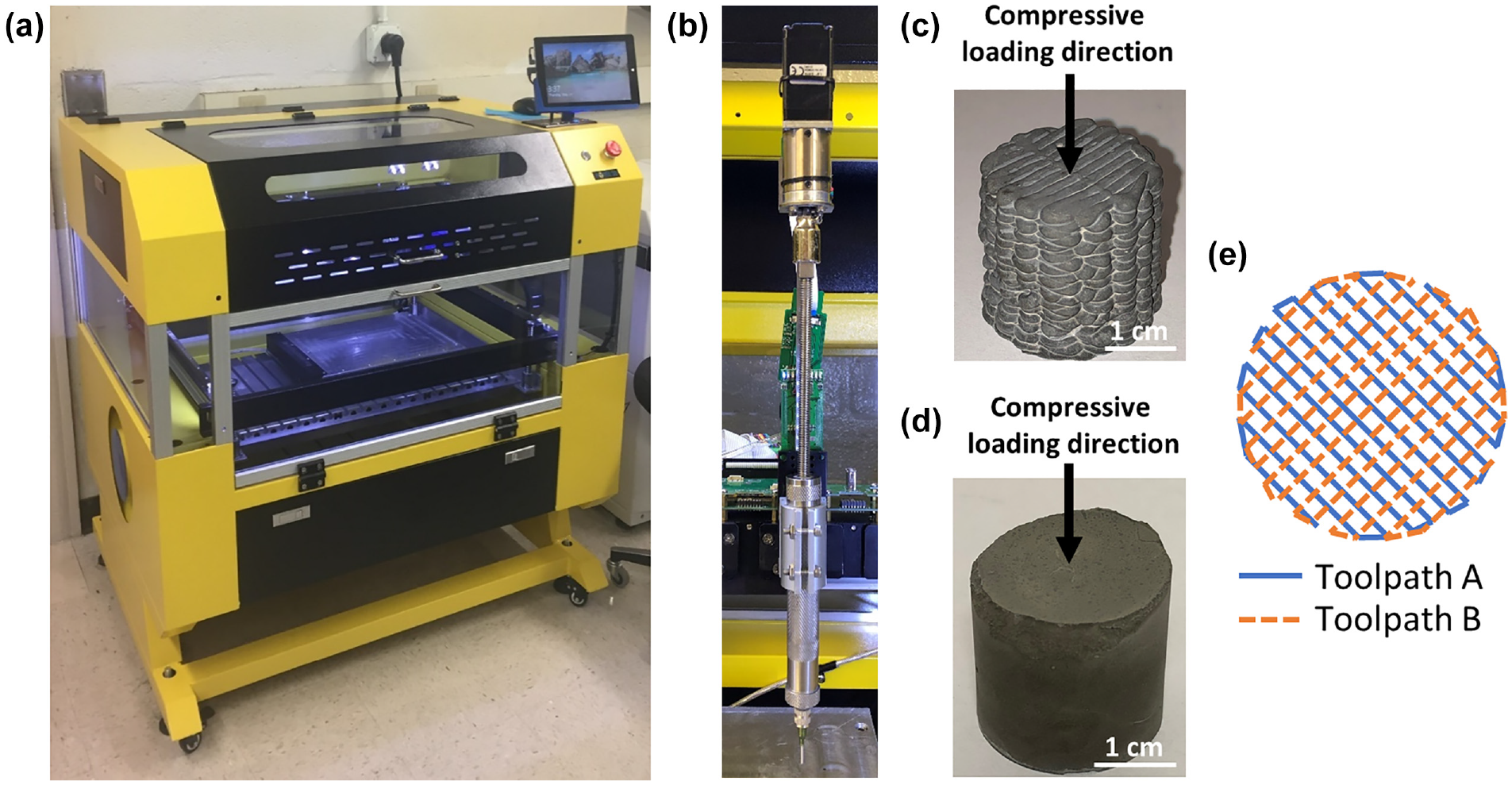
(a) Hydra 430 gantry model 3D printer used for printing cement composites, (b) EMO-XT print head assembly, (c) a 3D printed cement composite sample in a rectilinear pattern, (d) a cast cement composite sample, and (e) diagram of the toolpath used for 3D printing samples.
As a control, the cement composites were also cast into cylindrical molds such that the samples had a diameter of 2.54 cm and a height of ca. 2.5 cm (Figure 1d). Cast samples were then tamped 25 times with a 1.6 mm diameter stainless-steel rod. A minimum of five replicates of each cement composite type were made.
Characterization
Slump Test
Slump measurements were initially attempted with a miniature Abrams slump cone constructed from polytetrafluoroethylene ( 44 ). However, the cement inks tested were too viscous for this method and would not release from the cone under their own weight. Therefore, the cement inks were slump tested using a straight piece of polyvinyl chloride with an inner diameter of 4.1 cm and a height of 3.8 cm.
Scanning Electron Microscopy
An FEI Quanta FEG 650 environmental scanning electron microscope (SEM) (FEI Company, USA) equipped with a Schottky field emission gun and energy dispersive X-ray spectroscopy was used to collect SEM backscatter electron (BSE) images from the internal faces of fractured surfaces as well as polished samples recovered after material testing. Polished samples were epoxy mounted and polished in four steps, first with 320 grit and 600 grit silicon carbide paper, then with 6 µm and 1 µm diamond paste on a polishing cloth. An accelerating voltage of 15.0 keV, a chamber pressure of 130 Pa, and a working distance of 10.5 mm were used.
BSE images collected at 400x were thresholded using ImageJ (National Institute of Health, Bethesda, MD) to create a binary image that provided segmentation between unhydrated cement particles and all other phases. To prevent spurious results from microscale particles, only particles larger than 15 µm2 were included in the analysis. The final binary image was then analyzed for area coverage of the unhydrated cement particles. For each sample type, 50 images were analyzed. Similarly, large area BSE images of printed filaments of the 3D printed cement composite fabricated with the CF cement ink were analyzed using ImageJ software and in-house developed Matlab codes to determine the density and the average minimum CF-to-CF distance.
Compressive Testing
Before compressive testing, the top and bottom surfaces of the 3D printed and cast samples were ground using a 320 grit polishing cloth until each surface was within 0.5 degrees from perpendicularity to the axis according to the specifications in ASTM C39 ( 45 ). Compressive testing was conducted at seven days of age using an MTS 810 material testing system (MTS Systems Corporation, USA) in displacement-control mode with a loading rate of 5 µm/s according to a modified ASTM C39 ( 45 ). The load was applied along the build direction from the top surface of the 3D printed samples, such that it was orthogonal to both directions of the rectilinear print path (Figure 1c, d and Figure 4b, c). The load direction with respect to the print path was selected to account for the anisotropic nature of 3D printed materials. The literature has shown that the orientation of the print pattern with regard to the compressive loading direction can have a direct influence on the material compressive properties with the highest strengths expected when the load is applied orthogonally to the print path ( 1 , 12 , 23 , 46 ). A minimum of five rectilinear 3D printed and five cast samples of each cement ink type were tested. Testing was allowed to proceed until the load dropped to 25% of the maximum load.
Results and Discussion
Extrusion and Filament Formation
The early-age behavior of the tested cement inks was characterized by their stiff consistency and minimal slump (Figure 2a). The low slump of the cement inks was necessary to allow each printed filament to support the weight of subsequent layers without deformation and to preserve the shape integrity of the overall structure. No significant difference in the slump behavior was seen between the different cement inks.
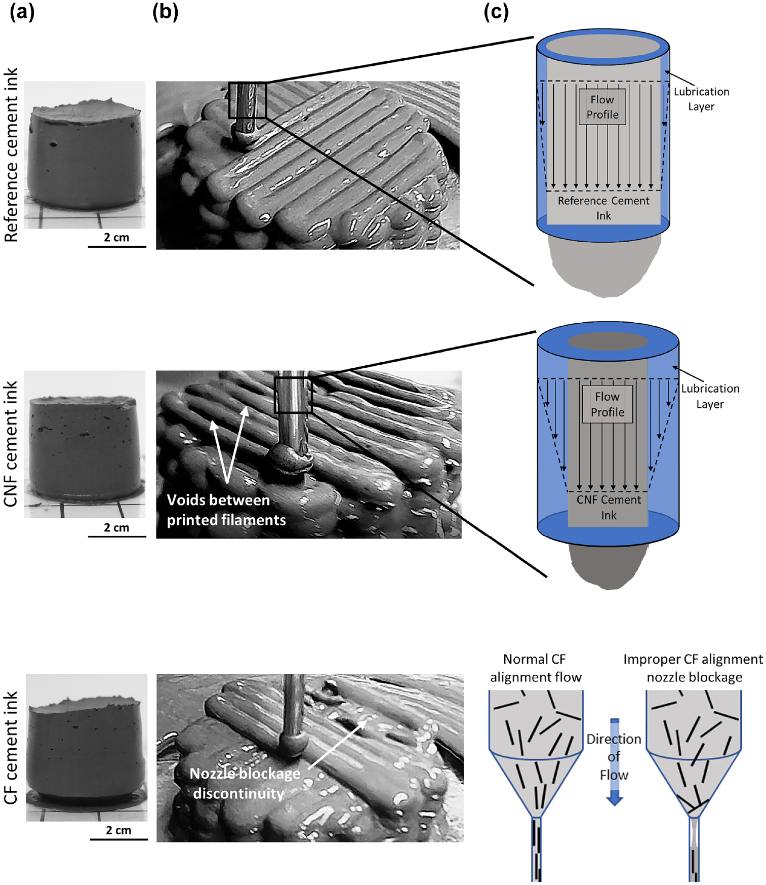
(a) Slump, (b) filament extrusion, and (c) nozzle flow schematics for the 3D printed cement composites fabricated with the reference cement ink, CNF cement ink, and CF cement ink.
During the extrusion process, a layer of water could be observed at the surface of the printed filaments with all cement inks (Figure 2b). This layer of water was thought to be the result of water being driven from the bulk cement ink into the extruded filament because of the extrusion pressure inside the 3D print head (liquid phase filtration), which resulted in the formation of a lubrication layer along the wall of the nozzle (drainage) that facilitated the flow of the cement ink. Consequently, the remaining cement ink in the 3D print head after completion of the print appeared considerably dryer and more consolidated than the extruded cement ink. The sensitivity of cement pastes during extrusion to drainage and liquid phase filtration through the granular solid has been previously reported in the literature ( 47 ). These observations further indicated the heterogeneous evolution of the cement ink inside the 3D print head with the formation of a consolidated, low-water content zone and the presence of a high-water content, shearing zone at the extrusion nozzle.
The reinforcement type was found to influence the mechanism of the extrusion process. The cement ink with CNFs tended to underextrude, producing a printed filament with a smaller diameter compared with that obtained using the reference cement ink, while the cement ink with CFs tended to be subjected to sudden discontinuation of extrusion and occasionally resulted in a failed print (Figure 2c). The underextrusion seen with the CNF cement ink was thought to be caused by the hydrophobicity of the CNFs, which, locally, repelled water into the bulk of the cement ink and under the extrusion pressure drove some of the water out of the cement ink, resulting in a thicker lubrication layer (i.e., more drainage). This led to a thinner diameter printed filament compared with that of the reference cement ink printed under the same conditions. The discontinuation in the filament extrusion with the CF cement ink was thought to be because of a combination of blockages caused by the CFs that were transverse to the printing nozzle and were not able to pass through (1.6 mm nozzle diameter versus average CF length of 3–6 mm) and an increased viscosity of the cement ink in the presence of CFs that limited the migration of paste water through the print head and thus liquid phase filtration. Short carbon fiber additions have been shown in the literature to increase the viscosity of fresh cementitious materials ( 48 ).
Microstructural analysis of the 3D printed and cast cement composites further revealed that the 3D printing process influenced the level of unhydrated cement particles in the composites at seven days, as shown from the differences in their percentage of surface coverage in the composite cross section (Figure 3). The presence of unhydrated cement particles in the 3D printed cement composites was further influenced by the effect of the fibers on the extruded filament formation during the extrusion process in the case of the CFs. The 3D printed cement composites fabricated with the reference and CNF cement inks exhibited overall a lower percentage of surface coverage of unhydrated cement particles compared with their cast counterparts (ca. 13–14% versus ca. 15–17%), while the 3D printed cement composite fabricated with the CF cement ink had a higher percentage (ca. 21% versus ca. 17%).
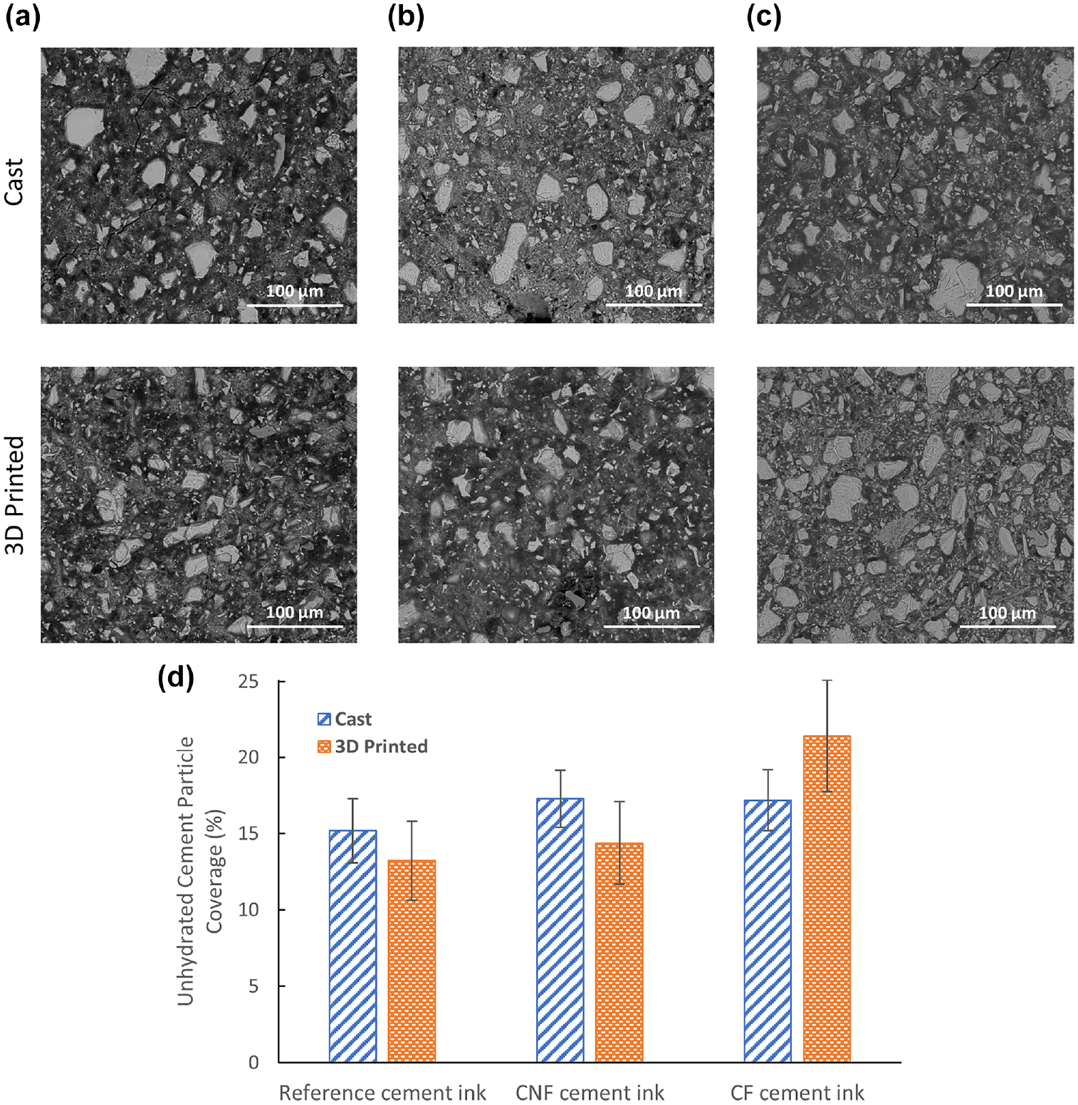
Backscatter electron (BSE) images of the cast and 3D printed cement composites fabricated with (a) the reference cement ink, (b) the CNF cement ink, and (c) the CF cement ink, showing unhydrated cement particles, and (d) percentage of unhydrated cement particle surface coverage for each cast and printed cement composite type.
The lower surface coverage of unhydrated cement particles (i.e., greater hydration) for the reference and CNF cement inks was in agreement with the presence of the liquid phase filtration during extrusion. The liquid phase filtration pushed water from the bulk cement ink inside the print head into the extruded filament, thus yielding a greater effective water-to-cement ratio in the printed filament compared with that of a cast cement paste. This greater effective water-to-cement ratio resulted in a lower surface coverage of unhydrated cement particles. In contrast, the higher surface coverage of unhydrated cement particles (i.e., lower hydration) for the CF cement ink was consistent with a lower liquid phase filtration because of the increased viscosity of the CF cement paste, which resulted in less water being pushed into the extruded filament and thus in a lower effective water-to-cement ratio in the printed filament.
Filament Morphology and Fiber Distribution
SEM images evidenced a heterogeneous distribution of the CNFs and CFs along the filaments in the 3D printed cement composites. For the 3D printed cement composite fabricated with CNF cement ink, a non-uniform distribution of individually embedded and clustered CNFs was found throughout the composites similar to that of the cast cement composite. Furthermore, no apparent preferential alignment of the individual CNFs or CNF clusters was seen in the 3D printed filaments, suggesting a limited influence of the 3D printing process on the distribution of the CNFs. The CNF clusters were randomly distributed within the cement composites and were of various sizes and shapes with a diameter of 50 µm or less. It was thought that the low slump of the tested cement inks mitigated the presence of bleed-water for both the cast and the printed cement composites, limiting the movement of the CNFs through the hydrating cement paste and thus their reagglomeration. CNF clustering has been shown in the literature to be influenced by bleed-water with an increasing gradient in cluster size in the direction of bleed-water migration ( 49 , 50 ) and to be reduced by hindering the movement of the CNFs in the fresh cement paste ( 40 , 51 ). Studies and methods of quantification of CNFs in cement pastes can be found elsewhere ( 40 , 50 ).
In contrast, the 3D printed cement composite fabricated with CF cement ink exhibited a preferential alignment of the CFs, which was consistent with the directionality along the print path of the extrusion nozzle (Figure 4c). Nozzle induced preferential alignment of fibers has been previously reported in the literature ( 1 , 33 , 52 ). Additionally, the rectilinear printing pattern provided a layering effect in the CF alignment whereby fibers in each layer were oriented orthogonally to fibers in adjacent layers. Variations in CF distribution within a given layer were seen, with some areas having a high density of CFs and others having a low density (Figure 4d). As an example, for the filament shown in Figure 4d, the high CF density zone had a density of 24 fibers/mm2 and a CF-to-CF average minimum distance of ca. 0.10 mm while the low CF density zone had a density of seven fibers per mm2 and a CF-to-CF average minimum distance of ca. 0.15 mm. This non-uniformity in fiber distribution within a printed layer was thought to be because of the partial blockage of the extrusion nozzle with CFs during printing, which led to a sporadic release of the CFs with, in some cases, a lower density of CFs being released from the extrusion nozzle and in others a higher density of CFs being suddenly released. In contrast, the CFs in the cast cement composite had a more random orientation, which was consistent with the lack of extrusion pressure and lower confinement seen in traditional casting (Figure 4b).
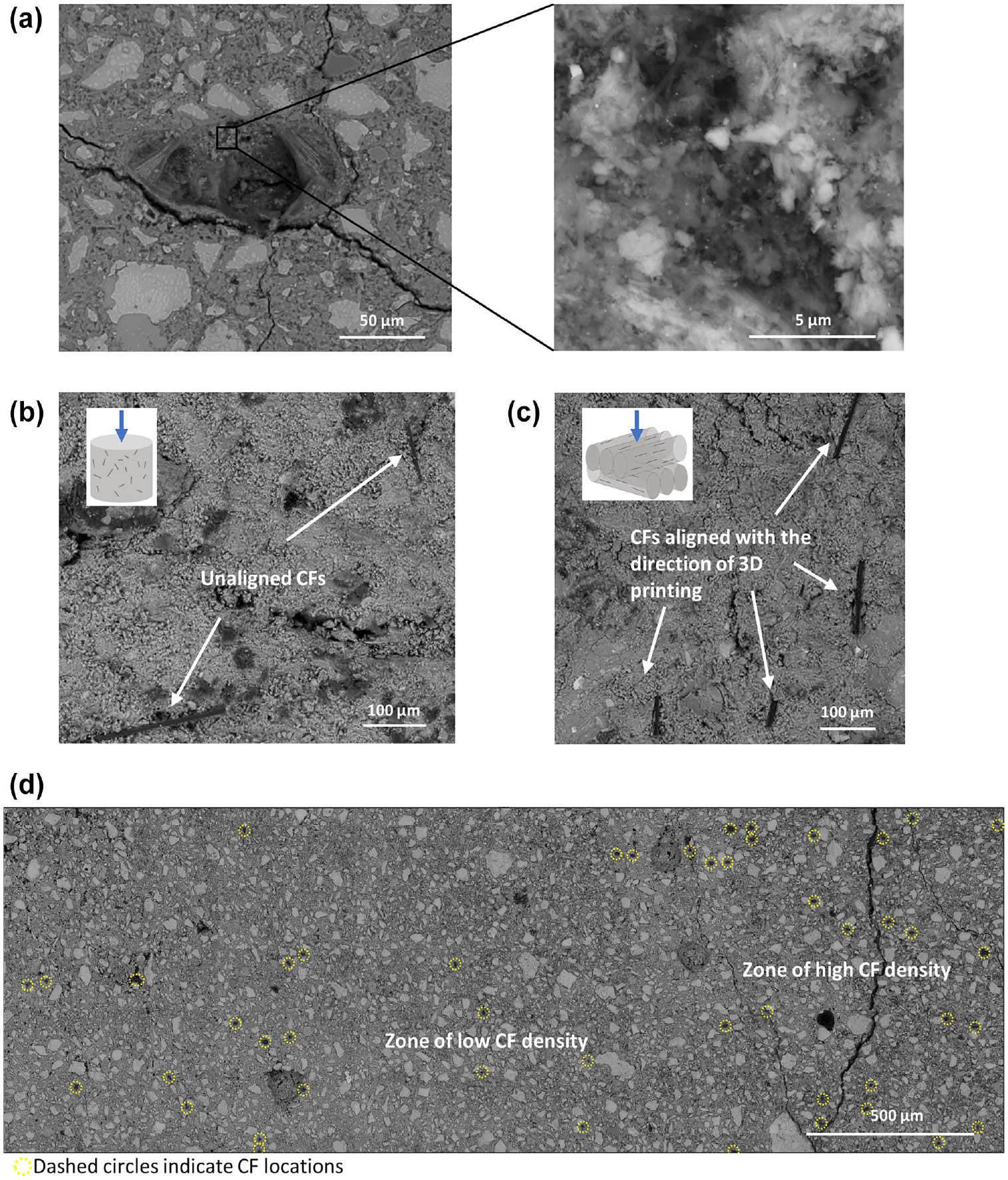
Backscatter electron (BSE) images showing (a) a CNF cluster with a closeup of the fiber entanglement, (b) unaligned CFs in a cast specimen and corresponding schematic for compressive loading direction, (c) aligned CFs in a 3D printed specimen and corresponding schematics for fiber alignment with respect to compressive loading direction, and (d) large area BSE image of a filament layer in the 3D printed cement composite fabricated with the CF cement ink.
Boundary Interface between Printed Filaments
Inspection using SEM analysis of the 3D printed cement composites generally did not show any distinctive change in microstructure that was characteristic of interfacial boundaries between printed filaments, with the exception of air cavities seen between printed filaments of the composite fabricated with the CNF cement ink (Figure 5). These cavities were consistent with the phenomenon of underextrusion observed with this cement ink. Examination of the mechanically tested 3D printed cement composite fabricated with the CNF cement ink indicated the presence of preferential cracking at the edges of the air cavities that coincided with the filament boundaries. This indicated a weaker interfacial bond between the filaments at the location of underextrusion. There did not seem to be, however, a notable difference in the microstructure composition between the areas surrounding the cavities and the other parts of the composite, with unhydrated cement particles being present up to the edge of the cavities (Figure 5b). For the 3D printed cement composite fabricated with the CF cement ink, there was no significant microstructural change indicative of the presence of an interfacial region between filaments. However, layers of alternating CF orientations within adjacent filaments could be seen, indicative of the rectilinear printing pattern (Figure 5c).
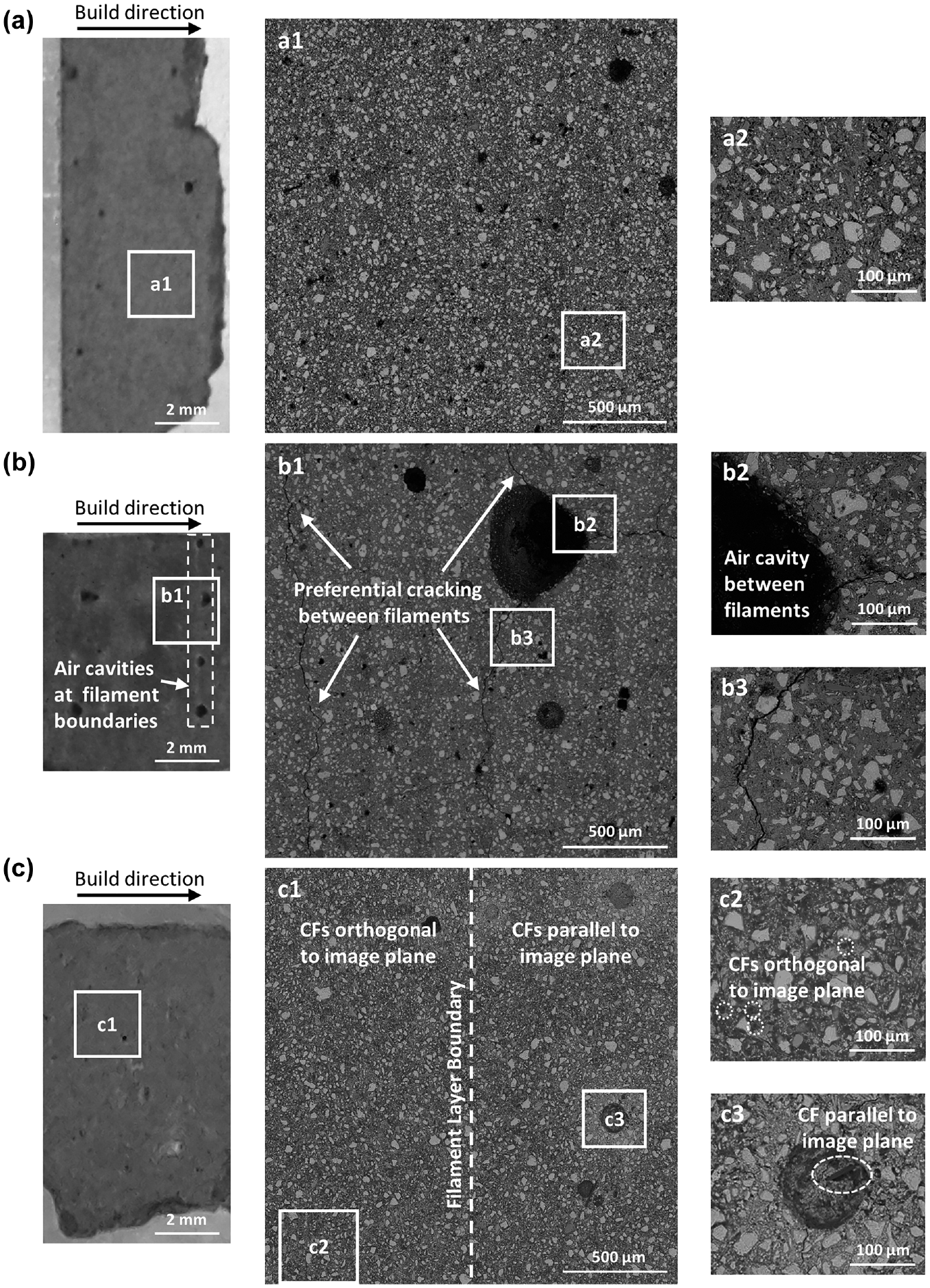
Photographs of representative specimens (left), backscatter electron (BSE) large area map (middle), and BSE images (right) of the 3D printed cement composites fabricated with (a) the reference cement ink, (b) the CNF cement ink, showing air cavities between printed filaments and preferential cracking, and (c) the CF cement ink, showing CF orientation in adjacent filament layers.
Compressive Strength at Seven Days
Overall 3D printing resulted in lower average compressive strengths of the 3D printed cement composites compared with their cast counterparts (Figure 6a). It was thought that load transfer differences between the cast and 3D printed cement composites contributed to the lower overall strength of the 3D printed specimens, with load being preferentially transferred in the 3D printed specimens along the boundary interface between the printed filaments.
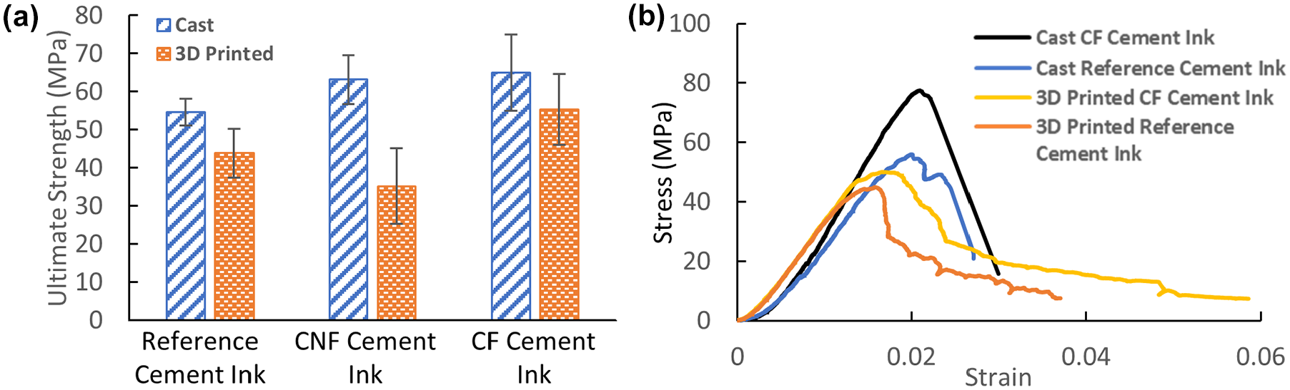
(a) Average ultimate compressive strength of each cement composite type and (b) typical stress-strain curves for the 3D printed cement composites fabricated with the reference and CF cement inks.
The type of fiber reinforcement (CNF versus CF) in the cement ink further affected the compressive strength behavior of the 3D printed cement composites. The cement composites fabricated with the CNF cement ink had a more drastic reduction in average compressive strength from cast to 3D printed (44%) as compared with those fabricated with the reference cement ink (20%) or with the CF cement ink (15%). The underextrusion seen in the 3D printing process for the CNF cement ink likely weakened the interfacial bonds between filaments, further reducing the load transfer capabilities of this 3D printed cement composite (Figure 5b). The smaller strength reduction of the 3D printed cement composite with CF cement ink was attributed to the compressive loading direction that was orthogonal to the aligned CFs along the direction of the print path, leading to a fiber loading condition that more closely mimicked flexural behavior. This unidirectional loading with respect to the fibers and print path was in contrast to that of the cast cement composite with CFs for which the CFs were in a random orientation. Embedded short fibers have been shown in the literature to provide the most benefit to the mechanical properties of the material when they are oriented orthogonally to the direction of the load ( 20 , 53 – 56 ).
The effect of the nozzle induced CF alignment and filament layering because of 3D printing was visible on the post yield stress behavior with the continued resistance to compression after the maximum yield stress had been reached. This was characterized in the compressive stress-strain curves (Figure 6b) by a continued increase in strain capacity with a tapering of the stress retained by the composite until final rupture (i.e., strain-softening behavior). A similar post peak stress behavior has been recently reported in the literature for 3D printed mortars with short straight steel fibers during flexural testing ( 25 ).
Conclusions
Cement inks with CNFs and CFs were developed and used to fabricate internally reinforced 3D printed cement composites. The extrusion process resulted in a heterogeneous evolution of the cement ink inside the 3D print head with the presence of a high-water content, shearing zone at the extrusion nozzle as a result of liquid phase filtration inside the 3D print head. The CNF cement ink tended to underextrude (thinner printed filaments) because of the hydrophobic character of the CNFs, while the CF cement ink led to sudden discontinuation of extrusion and occasionally failed prints because of transverse orientation of CFs with respect to the nozzle. The underextrusion seen with the CNF cement ink led to regularly spaced air cavities between the printed filaments, likely weakening the bond between the filaments and reducing the load transfer capability of the 3D printed cement composite. In contrast, no notable interfacial regions between printed filaments in the 3D printed cement composites were found with the other cement inks. For the CF cement ink, the extrusion resulted in a nozzle induced preferential alignment of the CFs along the print path because of the greater length of the fibers relative to the diameter of the nozzle. While 3D printing resulted in lower compressive strength of the composites in the direction orthogonal to the print path compared with traditional casting, the addition of CFs within the cement ink reduced the strength difference between the cast and 3D printed cement composites and provided a strain softening in the post peak behavior. Further research is needed to better understand the implication of the liquid phase filtration and lubrication layer and the effect of a larger extrusion nozzle. Additionally, the orthotropic mechanical response of 3D printed cement composites as a result of fiber alignment at the microscale should be further investigated to design components with locally controlled mechanical properties.
Footnotes
Acknowledgements
The authors thank the BASF chemicals company and LafargeHolcim for providing materials.
Author Contributions
The authors confirm contribution to the paper as follows: study conception and design: M. Kosson, L. Brown, and F. Sanchez; data collection: M. Kosson and L. Brown; analysis and interpretation of results: M. Kosson, L. Brown, and F. Sanchez; draft manuscript preparation: M. Kosson, L. Brown, and F. Sanchez. All authors reviewed the results and approved the final version of the manuscript.
Declaration of Conflicting Interests
The author(s) declared no potential conflicts of interest with respect to the research, authorship, and/or publication of this article.
Funding
The author(s) disclosed receipt of the following financial support for the research, authorship, and/or publication of this article: This research was supported by the National Science Foundation under NSF CMMI 1563389 and is part of a collaborative research between Purdue University (Profs. Zavattieri, Olek, Youngblood) and Tennessee Technological University (Prof. Biernacki).