
Abstract
Compaction is one of the most critical steps in asphalt pavement construction. Traditional compaction relies heavily on engineering experience and post-construction quality control and can lead to under/over compaction problems. The emerging intelligent compaction technology has improved compaction quality but is still not successful in obtaining mixture properties of a single pavement layer. Besides, very few studies have discussed the internal material responses during field and laboratory compaction to explain the meso-scale (i.e., particle scale) compaction mechanism. Knowledge in those areas may greatly promote the development of smart compaction. Therefore, this study aims to investigate the kinematic behavior of the asphalt mixture particles (translation and rotation) under six types of field and laboratory compaction methods and establish the relationship between the field and the laboratory compaction by using a real-time particle motion sensor, SmartRock. It was found that particle movement pattern was mainly affected by the compaction mode. At the meso-scale where particle behavior is the focus, the kneading effects of a pneumatic-tire roller can be simulated by laboratory gyratory and rolling wheel compaction, and the vibrating effects of a vibratory roller can be simulated by Marshall compaction. However, none of those laboratory compaction methods can completely simulate the field compaction. Under vibratory rolling, particle acceleration decreased fast in the breakdown rolling stage. Under pneumatic-tire rolling, particle angular position change was related to aggregate skeleton, and particle relative rotation showed a decreasing trend that was consistent with the laboratory gyratory compaction results. Those kinematic responses can potentially be used to monitor density change in field compaction.
Compaction is one of the most critical steps during the construction of asphalt pavement. It is a process during which asphalt mixture particles continuously move, rotate, and interact with each other under external compactive efforts to eventually achieve a stable structure ( 1 , 2 ). The quality of compaction controls pavement density (air void content, size, and distribution), the smoothness, the uniformity, and the volumetric and mechanical properties of materials, and is ultimately related to the performance and durability of the pavement.
Field asphalt pavement compaction is usually a combination of static rolling, vibratory rolling, and sometimes pneumatic-tire rolling as well. At present, the control of asphalt pavement field compaction still relies heavily on the knowledge and experience of field personnel, although many factors like subbase stiffness, ambient temperature, and wind speed can affect the compaction process together with the material properties ( 3 ). Traditional methods, including nuclear and non-nuclear density gauge, coring, ground penetrating radar, and so on, have been used for compaction quality control (QC). Although effective, they can only provide density information after compaction, which may increase the probability of under/over compaction and low pavement uniformity. Intelligent compaction (IC) technology has rapidly developed in recent years as a potential supplement to the traditional compaction method which could improve this situation. IC uses vibratory rollers equipped with an integrated measurement system, global position system (GPS), infrared temperature sensors, and onboard reporting system. Researchers have reported the benefits of IC, including improved compaction uniformity, real-time display of roller passes, pavement surface temperature, accurate identification of weak spots, and so forth ( 4 ). But technical difficulties still exist that prevent IC from further popularization. For example, IC measurement values (ICMV) showed inconsistent correlations with densities, which was partially attributed to the complex vehicle-surface interactions and the effect of asphalt binder viscosity on the rebound behavior of the roller drum ( 5 ). Also, the ICMV represented the overall stiffness of the entire pavement system instead of a single layer ( 6 ). Also, the depth of compaction that can be achieved by various IC roller for various soils remains unknown ( 6 ). It is hypothesized that enhanced understanding of internal asphalt mixture responses during compaction could contribute to a more reliable and accurate IC technology.
In the meantime, several laboratory compaction methods have been utilized to mold specimens similar to the field compacted mixtures so that the design and engineering properties of the road material can be conveniently researched through laboratory testing setups. The most commonly used laboratory compaction methods include gyratory compaction, Marshall impact compaction, rolling wheel compaction, and so forth. Many researchers found that the gyratory compaction method can simulate the field more closely because it applied both shear and compression simultaneously to the mixture ( 7 , 8 ). The Superpave gyratory compactor (SGC) was developed as a practical device to be implemented in Superpave mix design ( 2 ). Further, studies were conducted to investigate the internal structure of compacted asphalt mixture. Tashman et al. and Masad et al. applied x-ray computed tomography (CT) technology in their studies to look into the inside of field cores and laboratory compacted specimens ( 9 – 11 ). The air void distribution, aggregate orientation, contact number, and so forth. were quantified. Discrete element method (DEM) was also used to investigate the effect of compaction on specimen air void distribution ( 12 ). Results showed that compaction methods had significant effects on air void distribution in both vertical and lateral directions.
During the compaction process, individual particles move and interact with each other, which can affect the volumetric properties of the final asphalt mixture product and can have direct impact on the mechanical performance of the mixture ( 13 ). The previous analyses were mostly based on several compacting moments instead of a continuous process. A recent study solved this problem by using a prototype particle scale wireless sensor, the SmartRock sensor, to analyze particle movement characteristics in SGC compaction. It was found that particle rotation was closely related to asphalt mixture density change ( 1 ). Further field pavement compaction study presented particle response patterns under the effects of different types of rollers. Results showed that the pneumatic-tire roller could well simulate the kneading effects of the SGC ( 14 ). Compared with other sensors, such as the fiber Bragg grating sensor, the SmartRock sensor is easy to install and has minimal disturbance to the surrounding asphalt mixture ( 15 ). It has the advantage and potential to be applied in field asphalt pavement compaction monitoring.
The final property of the mixture, theoretically determined by the design of the asphalt mixture, is, however, affected by the compaction method and the conditions ( 12 , 16 , 17 ). Current experience-based asphalt pavement field compaction and its post-construction QC methods bring many compaction-related issues, such as under/over compaction and low uniformity. The emerging IC technology has been developed to improve compaction in the field, yet it still has a long way to go before realizing an accurate automatic QC for the asphalt pavements. On the other hand, the mechanical properties of the laboratory specimens and the field cores were still very different ( 18 – 20 ). Their compaction mechanisms of different types of compaction methods need to be further investigated. It is believed that the lack of fundamental understanding of the material response during field and laboratory compaction at the meso-scale has been a major knowledge gap within the existing asphalt mixture compaction field. The meso-scale is an intermediate scale between macro-scale and micro-scale, and refers to particle units in this study. Knowledge in those areas may promote the realization of smart compaction as a three-step process: (1) enhance the fundamental understanding of compaction mechanisms, (2) develop/improve innovative methodologies for pavement compaction and QC, and (3) modify laboratory compaction methods for more reliable laboratory-based asphalt mixture research and mixture design. This study mainly focuses on steps 1 and 2, and step 3 will be studied in the future.
Research Objectives
The overall objective of this study is to investigate the distinctive characteristics of asphalt mixture under each type of compactive effort, both in the field and in the laboratory, and establish the relationship between laboratory compaction and field compaction modes based on the mixture’s meso-scale kinematic behavior. This paper will start with analyzing particle movement in different types of asphalt mixture and compaction modes, explain how the laboratory compaction can simulate the field at particle scale, and discuss the particle movement changing characteristics in field compaction. The real-time particle sensor, called SmartRock, was employed in this study to obtain the particle movement results in all the tests.
SmartRock Sensing
SmartRock is a prototype wireless particle sensor first developed and implemented in the railroad industry to study the movement and kinematics of ballast material ( 21 – 23 ). Now, it has been successfully expanded to the area of bridge deflection detection, tunnel deformation measurement, building settlement monitoring, asphalt pavement/base course compaction, traffic information perception, and so forth. To be used in asphalt mixture study, it is modified to a reduced size with an outside shell size of 27 mm (Figure 1d). The 3D printed external shell of SmartRock uses high-strength, high-temperature resistant thermoplastic polymer material, acrylonitrile butadiene styrene (ABS) with nylon, so that SmartRock can survive high temperature (up to 150°C) and heavy roller compacting force. As shown in Figure 1c, the external shell has good compatibility and cohesion with asphalt material. The size, shape, and edge angle of the SmartRock can be made to be similar to real stones if needed (Figure 1, a and b). The inside of SmartRock is equipped with a tri-axial accelerometer, a tri-axial gyroscope, a tri-axial magnetometer, three directional stress gages, and a temperature sensor, which can record three-axial particle translation, rotation, orientation, normal stress, and environment temperature. The data can be submitted to a portable receiver or remote-control field receivers through Bluetooth Low Energy technology or other communication protocols. Compared with many conventional sensors used in asphalt pavement, SmartRock is stable, durable, and convenient to be used practically because of its special internal and external design.
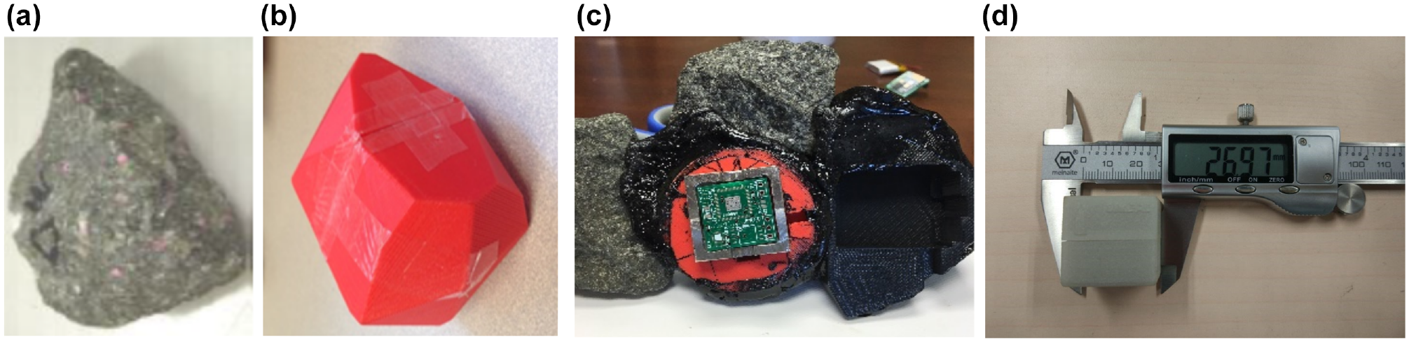
SmartRock sensors: (a) Granular aggregate, (b) 3D printer printed SmartRock shell, (c) SmartRock coated with asphalt, and (d) size of SmartRock.
Material and Experiments
Field Projects
The field project was a newly built lane-widening asphalt pavement with cement stabilized macadam base in China. SmartRock was embedded at the bottom asphalt mixture layer with a design thickness of 11 cm. The mixture was asphalt concrete (AC)-25 designed following Superpave mix design method using SGC, and the nominal maximum size of aggregate was 25 mm. Aggregates were limestone. The design asphalt content was 3.9%, and the voids in the mineral aggregate (VMA) and voids filled with asphalt (VFA) of the mixture were 12.4% and 67.5%, respectively. The asphalt binder was PEN 70 with no polymer modification. Field core test results showed an average pavement air void of 3.9% with a 1.3% standard deviation.
As shown in Figure 2, two SmartRock sensors were embedded at the bottom of the layer under the wheel path, with a longitudinal distance of 3 m apart from each other. The main consideration for SmartRock placement included sensor survival rate, reduction of boundary effect, and practicality of achieving longer-term performance monitoring. It was found that the method of SmartRock placement was reasonable and SmartRock responded actively toward different rollers. The coordinates and paving direction were also shown in Figure 2. This coordinate was the local coordinate determined in the initialization process before the compaction project started. Collected data was transformed to this coordinate for analysis. The detailed information of the initialization process and transformation method can be found in reference ( 1 , 14 ).
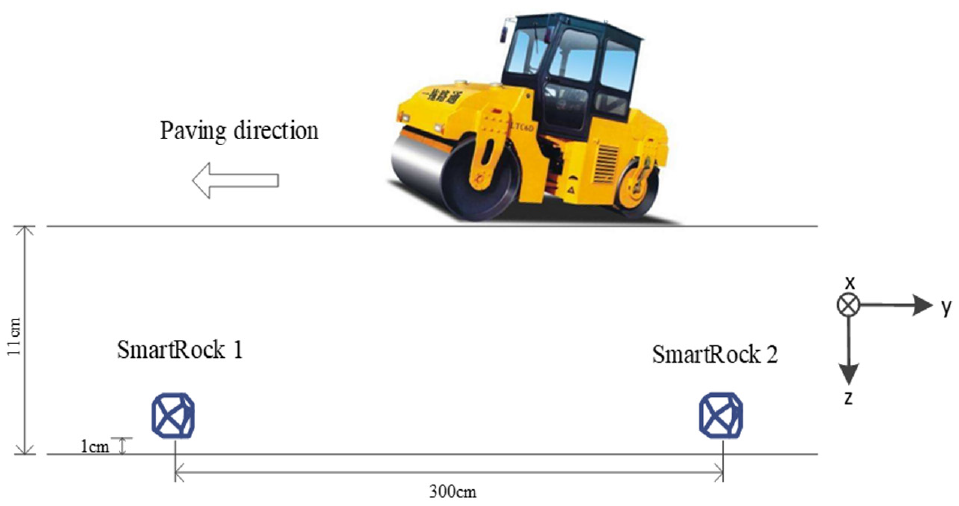
SmartRock layout in the field.
Three types of rolling methods were used in this project: the static rolling, vibratory rolling, and pneumatic-tire rolling. The rollers used were HAMM HD138 32 kg/cm tandem drum roller and XCMG XP302 pneumatic-tire roller with four wheels at front and five wheels at back. The pneumatic-tire roller was the main type of roller used in this project. Three types of rolling methods worked together in the 2 min long breakdown rolling stage to improve the stability of the asphalt mixture. The intermediate compaction stage was mainly composed of pneumatic-tire rolling and vibrating rolling for about 25 min. In the last 5 min long finish rolling stage, an additional three to four passes of a lighter weight pneumatic-tire roller were utilized for roller marks removal. The compaction ambient temperature was 10°C–15°C from recorded SmartRock data. The detailed information of this field project has been introduced in a previous study by the authors ( 14 ).
Laboratory Experiments
Three types of laboratory compaction methods, gyratory compaction, Marshall compaction, and rolling wheel compaction were tested with SmartRock inside to record particle responses. The compaction equipment was an AFG2 gyratory compactor from Pine Company, an LX-MDJ-I Marshall compactor from Nanjing Lingxian Pavement Instrument Manufacturing Company, and an advanced asphalt slab roller compactor from Controlsgroup. The gyratory compactor calibrated internal angle was 1.15°, and the compaction pressure was 600 Kpa. A 150 mm diameter mold was used in gyratory compaction. The Marshall compaction frequency was 1 Hz, and the mold diameter was 101.6 mm. The roller compactor was set at a rolling speed of 20 passes/min, and the load threshold value was 10 KN. The mold dimension was 400 mm × 300 mm. As for the SmartRock sensor placement location, it should be placed at a position that could represent the compaction method. Based on the previous study, mid-center position was a representative location for SGC compaction with minimal boundary effect ( 3 ). Therefore, the other two compaction methods also set the SmartRock in the mid-center position (as shown in Figure 3). By placing half the quantity of the asphalt mixture into the mold first, SmartRock was then set on the surface and the remaining half of the mixture was placed in the mold last. The whole process was quick and easy to handle. Particle motion data during the entire compaction was recorded and stored in a computer through Bluetooth. Compaction stopped when the mixture reached the target air void 4% ± 0.5%. The experiment was repeated at least three times for each compaction method to evaluate the repeatability of the results.
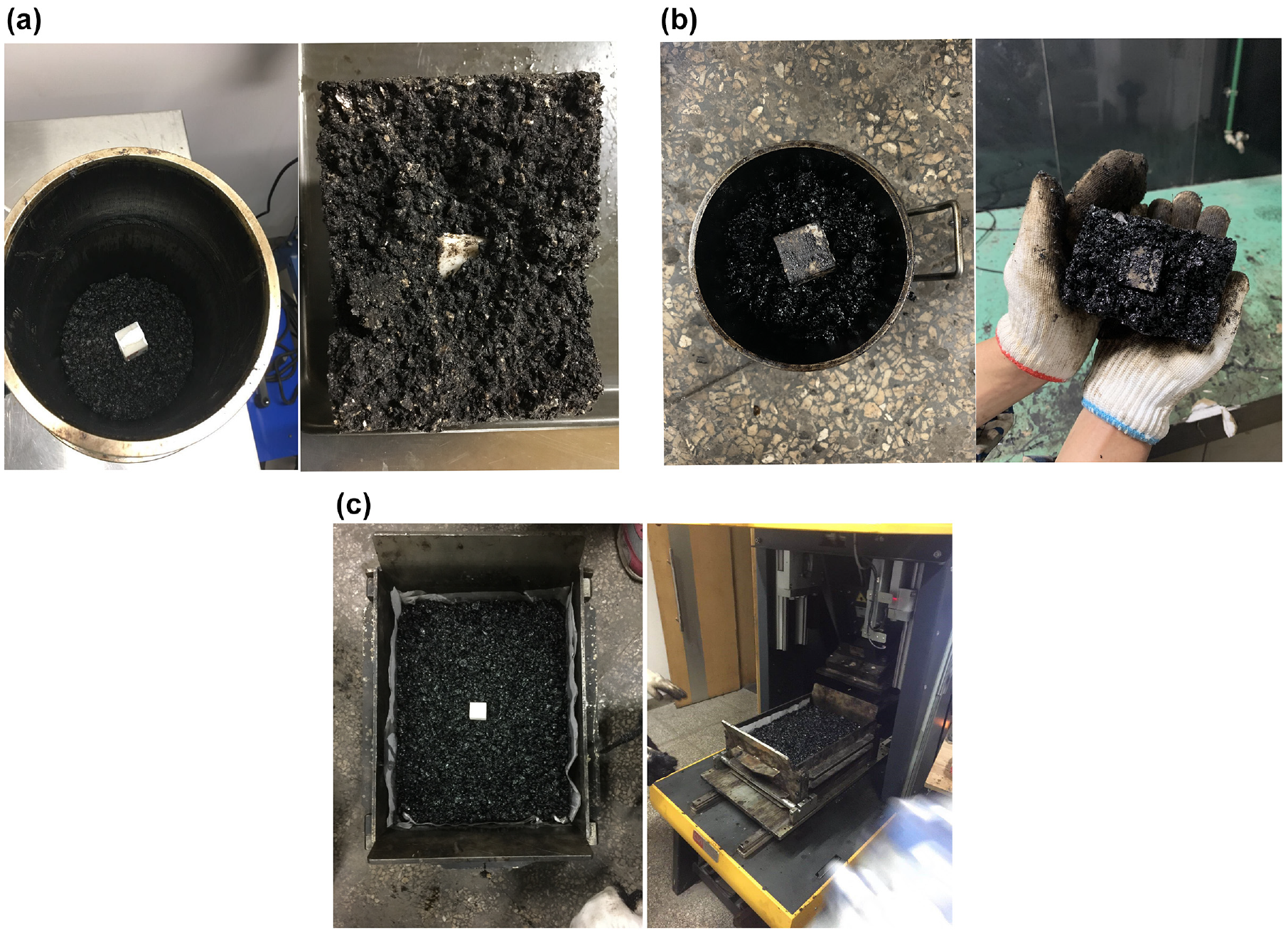
SmartRock in laboratory compaction: (a) Superpave gyratory compactor (SGC), (b) Marshall compaction, and (c) rolling wheel compaction.
The mixture used in the laboratory was asphalt concrete (AC)-12.5 with a nominal maximum aggregate size of 12.5 mm. This mixture is different from the field experiment because of practical limitations. To address the effect of mixture type on the compaction behaviors, a separate analysis was conducted and detailed in the section “Effect of Mixture Type on Particle Movement.” The mixture had an asphalt content of 5.8% and the asphalt binder was PG 64-22. The uncompacted void content of the fine aggregate is 48.4%. The percentages of one-face crush and two-face crush particles in the coarse aggregate are both 100%. The percentage of flat and elongated particles in the coarse aggregate is 8.4%. Field and laboratory asphalt mix design information is summarized in Table 1. Details of the experimental procedures can be found in Wang et al. ( 1 ).
Asphalt Mixture Design Information
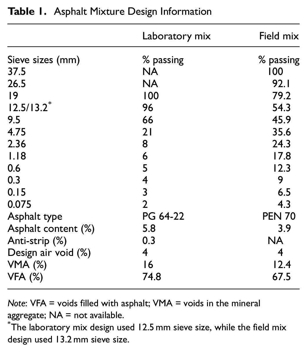
Note: VFA = voids filled with asphalt; VMA = voids in the mineral aggregate; NA = not available.
The laboratory mix design used 12.5 mm sieve size, while the field mix design used 13.2 mm sieve size.
It is worth noting that the size of the SmartRock used in this study is 27 mm in cubic shape (less than 1/5 of the gyratory mold diameter and less than 1/3 of the Marshall mold). Although larger than the coarse aggregate, its good compatibility and cohesion with the nearby asphalt particles allowed it to move (rotate and translate) collectively with the nearby asphalt particles. Therefore, it is believed that it can be used to study the motion characteristics of the particulate asphalt mixtures.
Real-Time Particle Responses to Compaction
Effect of Mixture Type on Particle Movement
Investigation of particle movement characteristics will help to explain asphalt mixture compaction mechanism at the meso-scale. How a particle moves during compaction can be represented by its translation and rotation, and rotation is particularly important under shear loading ( 1 ).
Because the asphalt mixture in field and laboratory compaction was different, a comparison test was designed using the field AC-25 mixture and the laboratory AC-12.5 mixture in SGC compaction to study the effect of mixture type on particle movement. The particle movement results as one of the three repetitions are shown in Figure 4. Other repetitions show similar results. It can be seen that, for both particle rotation and acceleration, there were some differences in their responding magnitude, but the pattern did not change with asphalt mixture type. The difference between particle response magnitude was small and would not have significant effects on the further comparison of particle movement in different types of compaction mode. Overall, the type of mixture had no fundamental effects on the asphalt mixture’s response results (both rotation and translation) under a particular compaction effort. It is hypothesized that particle movement characteristics were mainly affected by the compactor/roller working mechanism.
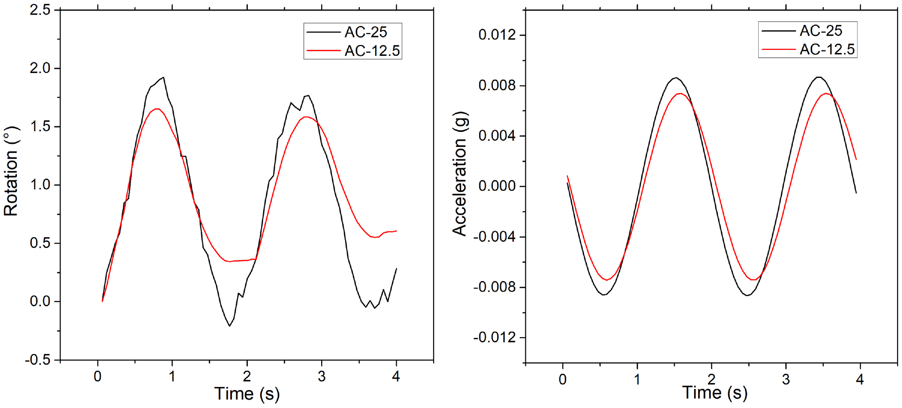
Particle movement in Superpave gyratory compactor (SGC) using different asphalt mixtures.
Effect of Compaction Mode on Particle Movement
In this section, particle movement under the effects of different compaction modes/efforts is presented. Table 2 summarizes the particle movement responses under a total of six types of compaction methods for both field and laboratory compaction. The replicate tests showed similar results, and the result of one test was used to show the typical particle responses. Particle translation and rotation are represented in the form of real-time SmartRock acceleration and rotation angle. Because the raw acceleration data was noisy as a result of electromechanical imperfections, environment disturbance, and geometric surface irregularities, the band-pass filtering technique was first adopted to process the raw data. All the particle acceleration results shown in this study were processed data. The laboratory results were in coordinates, with x-axis and y-axis on the horizontal plane, and z-axis in the vertical direction. For the rolling wheel compaction, the y-axis was in the wheel rolling direction, and the x-axis was perpendicular to it. How the particle moved in the three directions is briefly explained in Table 2. For example, the “x-, y-direction dominant” of particle rotation in gyratory compaction means that the particle had similar rotation pattern in three directions, but the rotation magnitude was larger in x- and y-directions than in z-direction.
Particle Movement in Different Types of Compaction Method
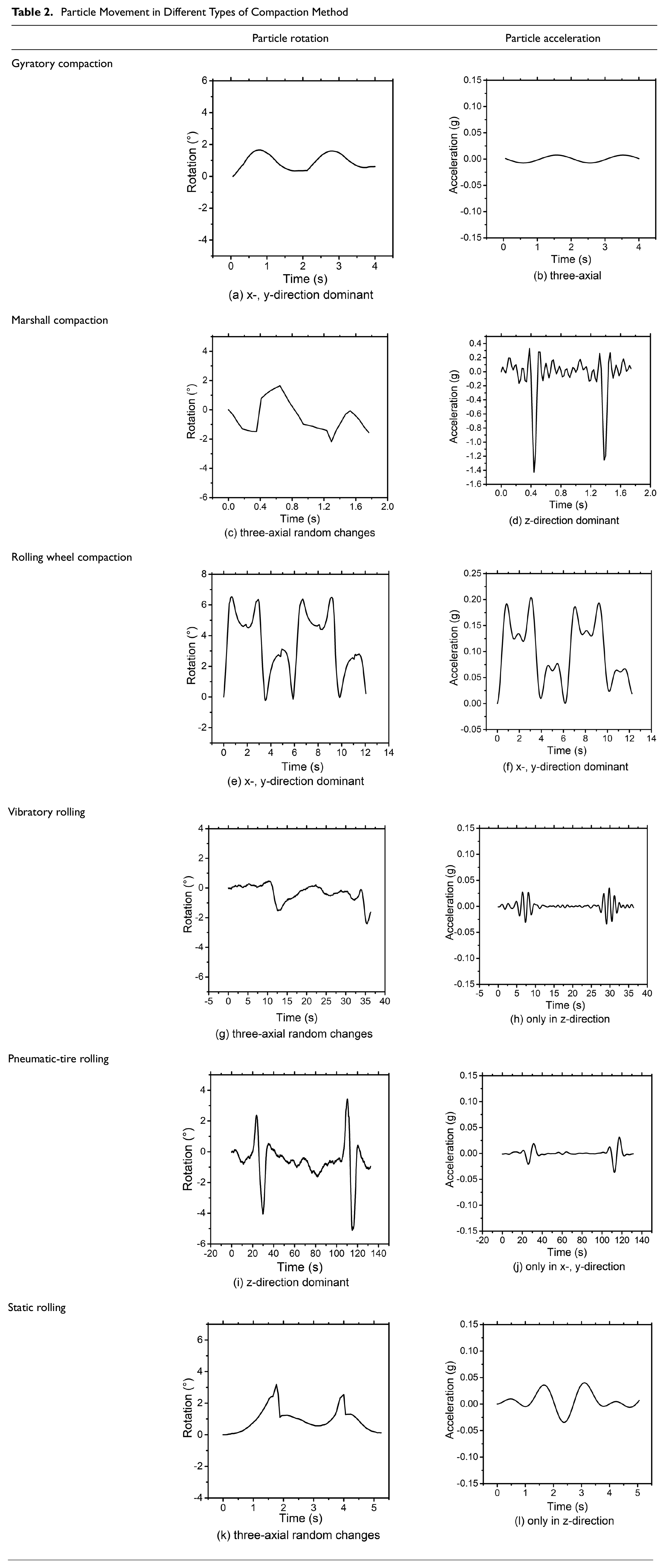
Generally, the particle had cyclic wave-shaped rotation and acceleration response curves in gyratory compaction, rolling wheel compaction, and pneumatic-tire rolling. This can be explained by the kneading effects of those three compaction methods on particle movement. Marshall compaction and vibratory rolling mainly contributed to particle vibration in the z-direction, and could only produce random particle rotation. For static rolling, the particle had no obvious vibrating translation or regular rotation.
Relationship between Field and Laboratory Compaction
Based on the information provided in Table 2, the particle-scale field and laboratory compaction characteristics and their relationship can be summarized as:
(1) For the field compaction, only the pneumatic-tire roller has kneading effects on the asphalt mixture, reflecting its regular particle rotation pattern. The horizontal particle translation along with particle rotation is also one of the unique characteristics of the pneumatic-tire roller. The static and vibratory roller mainly contribute to particle translation in the vertical direction, resulting in layer thickness reduction and mixture densification.
(2) For the laboratory compaction, both the gyratory and rolling wheel compaction have kneading effects on the asphalt mixture because of the shear forces applied to the mixture. The rolling wheel compaction has a more significant kneading effect with a larger particle rotation angle (6°) than the gyratory compaction (2°). The Marshall compaction mainly results in vertical particle translation for mixture densification.
(3) The laboratory gyratory compaction and rolling wheel compaction can simulate the kneading effects of the field pneumatic-tire roller. The gyratory compaction can simulate the particle rotation pattern of the pneumatic-tire roller, while the rolling wheel compaction can better simulate its magnitude. However, how they kneaded the particle was still different. It can be seen in Table 2, graphs a, e, and i, that the pneumatic-tire roller kneaded the particle mainly in the z-direction, but the gyratory and rolling wheel compaction kneaded the particle mainly in the x-and y-direction. The reason could be that the laboratory specimen size was limited, and the laboratory loading plate/rolling wheel was directly on top of the particle.
(4) The laboratory Marshall compaction can simulate the vibrating effects of the field vibratory roller, as showed by their particle acceleration results. However, the impact effects by the Marshall compaction was much more dramatic than the vibratory roller.
To summarize, from the particle movement perspective, different field compaction rollers can be simulated by different laboratory compaction methods. The kneading effects of pneumatic-tire roller and the vibrating effects of the vibratory roller in the field can be simulated by the laboratory gyratory/rolling wheel compaction and Marshall compaction, respectively. However, none of these three laboratory compaction methods can completely simulate field compaction. This explains the existing differences between laboratory specimen and field cores.
Particle Movement Characteristics in Field Compaction
It has been found that particle relative rotation was related to mixture density change in the laboratory gyratory compaction ( 1 ). As shown in Figure 4 and detailed in Wang et al., the particle followed a cyclic rotation pattern that repeated every 2 s during SGC compaction ( 1 ). The difference between the maximum and minimum rotation angle in each gyration cycle was defined as relative rotation. The particle relative rotation along the x- and y-direction in SGC compaction had a decreasing trend that correlated with the mixture density increasing trend. The z-direction particle relative rotation remained stable throughout the compaction process. In the field pneumatic-tire rolling, the particle had a wave-shaped rotation angle change during each time of roller pass (as shown in graph i in Table 2). The difference between the maximum and minimum value of the rotation angle change curve was the relative rotation for pneumatic-tire rolling, as indicated in Figure 5a. Also shown in Figure 5a is that the particle rotation angle did not return back to zero, indicating there was an angular position change after the roller drove away. Such angular position change could be related to the mixture densification process.
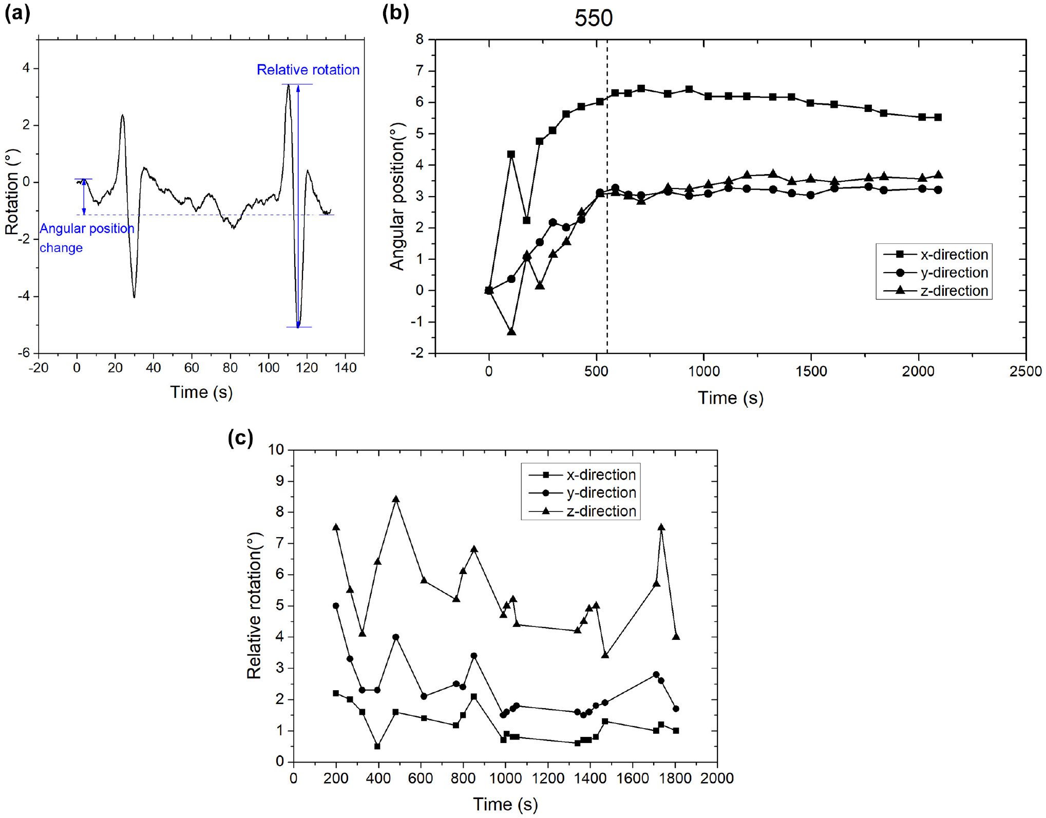
Particle movement characteristics changing trend in field pneumatic-tire rolling: (a) particle rotation characteristics, (b) particle’s angular position change, and (c) particle’s relative rotation change.
Figure 5b plotted the particle angular position change during compaction. It can be seen that the particle’s three-axial angular position changed continuously in the initial compaction stage and this process lasted for about 550 s in this specific project. After this, the particle remained at a stable angular position. This phenomenon was related to the particle interlocking characteristics during compaction, which can be used to explain the compaction process. In the compaction stage before this transition point, the particle was effectively interacting with other particles, and adjusting its position for a more stable and interlocked aggregate skeleton. However, there were hardly any aggregate skeleton adjustments after this transition point. Thus, the particle angular position changing curve can potentially be used to indicate the effectiveness of mixture compaction from the perspective of aggregate skeleton changes.
The particle’s relative rotation during the pneumatic-tire rolling process is shown in Figure 5c. It generally had a decreasing trend. The decreasing trend was more evident in the z- and y-direction than the x-direction, which was different from the laboratory SGC results. The difference could be explained by their different kneading mechanism. However, the decreasing trend of the particle’s relative rotation in the field was still consistent with that in the laboratory. The decrease of particle relative rotation can be used to indicate mixture density increase. In addition, the possible reasons for the changing curve instability could be attributed to the uncertain factors in field compaction, for example, the changing relative position of SmartRock and the roller.
For vibratory rolling, only z-direction acceleration presented a clear pattern and the particle’s rotation only had random responses. As shown in Figure 6, the particle’s maximum acceleration under the effects of the vibratory roller had a decreasing trend during compaction. The first two passes of vibratory rolling were in the 2-min-long breakdown rolling stage, and the latter five times of vibratory rolling were in the intermediate rolling stage. It can be found that the particle had a relatively large acceleration magnitude for the first two vibratory roller passes in the breakdown rolling stage, 0.9 g and 0.5 g, respectively. However, it quickly decreased to and remained in the range of 0.2 g to 0.3 g in the intermediate rolling process. This trend showed that the particle would have large translation under the vibratory roller when the asphalt mixture was quite loose. On the other hand, the role of the vibratory roller was especially critical in the breakdown rolling stage for effective asphalt mixture densification. After entering the intermediate rolling stage, the effects of the vibratory roller on particle acceleration became limited, indicating that the material deformation ability was reduced.
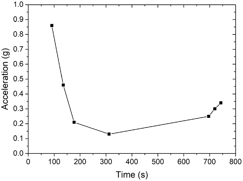
Particle’s acceleration magnitude in field vibratory rolling.
Conclusions
This study used SmartRock sensors in both field compaction project and laboratory compaction tests to investigate their particle movement behavior. Particle rotation and translation under different compaction methods were analyzed to explain the compaction mechanism, and discuss how laboratory compaction could simulate the field. The particle movement changing characteristics during field compaction were also analyzed.
It was found that the type of mixture had no fundamental effects on the asphalt mixture’s response pattern (both rotation and translation) under a particular compaction effort. The movement pattern of the particle was mainly affected by the compaction mode.
Generally, the laboratory gyratory compaction and rolling wheel compaction can simulate the kneading effects of the field pneumatic-tire roller. Also, the laboratory Marshall compaction can simulate the vibrating effects of the field vibratory roller. However, none of these three laboratory compaction methods can completely simulate the field compaction, which could be the reason for the existing differences between field cores and laboratory specimens. The understanding of the relationship between the laboratory and field compaction is of great significance to the improvement of the consistency between laboratory and field compaction, which will help to improve both the field pavement QC and reliability of laboratory tests.
The characteristics of the particle movement during the field compaction were analyzed. Under the effects of the pneumatic-tire roller, the particle’s three-axial angular position would change continuously at the beginning of the compaction (about 550 s in this project) and remain stable in the later compaction stage, which could represent the effectiveness of the aggregate skeleton adjustment. The field particle relative rotation showed a decreasing trend that was consistent with the laboratory SGC results. With the increase of the mixture density, the relative rotation of the particle would decrease. The real-time SmartRock rotation data during compaction can be potentially used as a critical parameter to monitor asphalt mixture density change. As for the vibratory roller, particle acceleration had a large value in the breakdown rolling stage, but quickly decreased to a small value in the intermediate compaction stage. The role of the vibratory roller in the breakdown rolling stage was critical for mixture densification.
Future Work
The findings in this study demonstrated the feasibility of using SmartRock sensors in asphalt mixture compaction monitoring, both in field projects and in laboratory tests. Because of the limitations of the field project, only one type of dense-graded asphalt mixture and the limited effect of SmartRock location were discussed in this study. Other mixtures and materials, as well as different lift thickness, could all follow different compaction characteristics and must be specifically studied. Along this path, a schematic plan for smart compaction can be proposed. IC can provide accurate information, such as roller pass number and pavement temperature, to improve the field compaction QC process. It also indirectly monitors the resultant responses of the pavement layers under compaction through external accelerometer measurement. The introduction of SmartRock can monitor the internal mixture kinematics of a specific pavement layer that was supplementary to the IC results. By combining IC and SmartRock technology, a quantitative relationship between the materials’ kinematic behavior under compaction and material property can be established so that real-time and accurate density/stiffness tracking can be realized. In addition, since SmartRock can track the particle motion characteristics under various types of compaction modes, it can be used as a convenient tool to improve laboratory compaction by simulating the field compaction mechanism from the perspective of particle-scale responses.
Footnotes
Acknowledgements
The authors would like to thank the technical support from the Sensor Technology Research Development and Application Laboratory (STRDAL) in Nanjing, Jiangsu Province, China. The authors also thank Cheng Zhang, Bin Shi, Zhidong Zhang, and Honglei Wang for their assistance in experiments and data collection.
Author Contributions
The authors confirm contribution to the paper as follows: study conception and design: S. Shen, H. Huang, X. Wang; data collection: X. Wang; analysis and interpretation of results: X. Wang, S. Shen; draft manuscript preparation: X. Wang, S. Shen. All authors reviewed the results and approved the final version of the manuscript.
Declaration of Conflicting Interests
The author(s) declared no potential conflicts of interest with respect to the research, authorship, and/or publication of this article.
Funding
The author(s) received no financial support for the research, authorship, and/or publication of this article.
Data Accessibility Statement
All data generated or analyzed during this study are included in this published article.