
Abstract
Steel-reinforced elastomeric bearing pads are widely used in bridge construction to vertically support girders on piers while also accommodating translational and rotational girder deformations caused by live loads and temperature changes. To support sloped girders, flat bearing pads of uniform thicknesses are typically used with either tapered steel shim plates or an inclined concrete bearing seat. The use of tapered pads has the potential to reduce both construction time and cost by eliminating the need for tapered plates or seats to match the girder slope. However, limited research has been performed to investigate the effect of introducing taper on relevant design properties of bearing pads. In this paper, results are presented from experimental testing that was performed to quantify the effect of taper on shear stiffnesses of pads having varied geometric characteristics (plan view dimensions, elastomer thicknesses, and slope angles). An experimental bearing pad test device was designed and utilized to impose shear loads in accordance with ASTM standards, while simultaneously maintaining a constant axial load. Bearing pads chosen for testing were tapered variations of standard flat bridge bearing pads used in the state of Florida, U.S. Results obtained from the study revealed that shear stiffness was not significantly influenced by the introduction of taper angle, the direction of shear along the length of pads, or axial load level. The shear stiffness of tapered pads remained within approximately 10% of the shear stiffness of corresponding flat pads.
Bridge girders and associated supporting elements, including bearing pads and substructures, are regularly subjected to combined vertical and horizontal forces. Self-weight of bridge components (girders, road deck, barriers, etc.) and weight of vehicles (trucks and cars) are primarily responsible for the vertical forces. On the other hand, thermal expansion and contraction of bridge components, as well as vehicle braking forces, are responsible for horizontal forces. Environmental loads such as wind and earthquake forces also impose vertical and horizontal forces on bridge structures. Structural demands caused by combinations of vertical and horizontal forces need to be considered during design to ensure bridge safety and serviceability.
At each girder support location, one or more bearings are placed between the bridge girders and the underlying substructure elements (abutments, piers) (Figure 1). The bearings serve both to distribute vertical forces from the bridge superstructure to the bridge substructure and to limit the transmission of horizontal forces that are caused by thermal movements. Consequently, bridge bearings must possess sufficient stiffness and strength to distribute large vertical loads, but sufficient flexibility to allow the superstructure to undergo horizontal movements without diminishing the structural integrity of superstructure or substructure components.
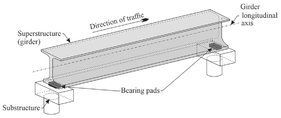
Location of bearing pads (not to scale).
Different types and shapes of bearings are available for use depending on the type of bridge and the expected deflection pattern. Different types of bearing pads include elastomeric bearing pads, pot and disc bearings, rocker and roller bearings, and spherical bearings. Elastomeric bearing pads are one of the most commonly used types of bearings for bridges because of their ease of installation and maintenance ( 1 , 2 ). Such pads generally consist of neoprene elastomer (a synthetic rubber-like material) with embedded steel reinforcing shim plates (Figure 2) that vary in thickness generally from 0.1 in. to 0.15 in. Neoprene is generally used in bearing pads because it has better resistance to heat, flames, and ozone attack compared with general-purpose elastomers; neoprene also has better adhesion to metals and resistance to weathering ( 3 ). Because bearing pads are designed to accommodate movements along the plane of the pad, the shear modulus of neoprene elastomer has a significant influence on the deformation behavior. The American Association of State Highway and Transportation Officials (AASHTO) permits the use of elastomer with shear modulus between 0.080 and 0.175 kips per square inch (ksi) ( 4 ). Elastomers with shear modulus greater than 0.175 ksi can reduce the ability of bearing pads to accommodate bridge movements. Given their low shear modulus, reinforced neoprene bearing pads may also be found to perform well under seismic loading ( 5 ).
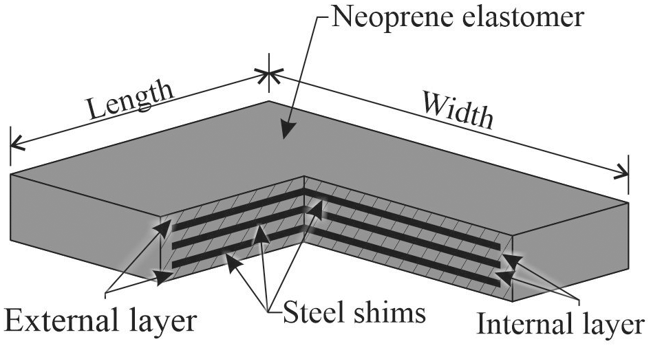
Rectangular steel-reinforced neoprene bearing pad.
The molecular structure of elastomers consists of strong and weak polymer chains. Under large shear strains, the weak polymer chains tend to break, which results in reduced shear stiffness of elastomers in subsequent cycles with smaller shear strains. This phenomenon is referred to as the Mullin’s effect ( 6 , 7 ). To remove the Mullin’s effect, standard testing methods for determining shear stiffness and modulus of bearing pads include conditioning procedures in which large shear strain cycles are imposed on the test specimen; this breaks the weak polymer chains that are found in newly fabricated bearing pads.
Elastomeric bearing pads are produced in varying geometric shapes and sizes, but rectangular and circular pads are the most common. For horizontal girders (Figure 3a), pads can be directly placed on the pier top surface to support the girder. In the case of girders at a slope, a leveling shim may be inserted between the girders and bearing pads (Figure 3b), or the bearing seat may be sloped to minimize the slope mismatch between girder bottom flange and bearing pad (Figure 3c). State departments of transportation dictate the requirements for use of either leveling shims or sloped bearing seats. For example, the Florida Department of Transportation (FDOT) permits the use of flat pads for beams with grade less than 0.5%, but requires the use of sloped bearing seats for beam grades between 0.5% and 2%. However, for beam grades greater than 2%, FDOT requires the use of leveling shims which introduce additional cost ( 8 ). For example, the leveling shim in Figure 3b can cost approximately the same as a bearing pad (based on the cost of 7/8 in. average thickness beveled plates purchased for the test setup used in this paper). However, slope mismatch can be more economically minimized by using tapered bearing pads (Figure 3d). Based on quotes obtained from three FDOT-approved bearing pad manufacturers, incorporating a slope of up to 5% into the manufacture of a tapered pad increases the cost by about 15%. Note that the theoretical shear stiffnesses of the flat bearing pads shown in Figure 3, a, b, and c, are same, and the shear stiffness of the tapered pad shown in Figure 3d is evaluated in this paper. Other practices used outside of Florida to match girder slope include the use of tapered sole plates vulcanized to flat elastomeric bearing pads.
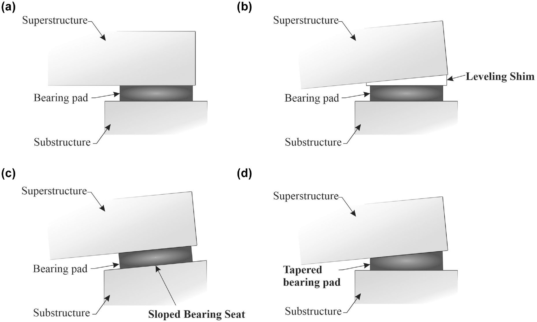
Bearing pad and bridge structure configurations using (a) Flat bearing pad; (b) Leveling shim and flat bearing pad; (c) Bearing pad and sloped seat; and (d) Tapered bearing pad.
AASHTO allowed the use of tapered bearing pads until 1992. However, after 1992, AASHTO restricted the use of tapered bearing pads because of potential issues identified such as increased shear strains in tapered elastomer layers compared with uniform thickness elastomer layers. As per AASHTO, section C14.7.5.1, increased shear strains can result in premature pad failure because of delamination or rupture of reinforcing steel shims ( 4 ).
A 1995 experimental study funded by the Texas Department of Transportation (TxDOT) demonstrated that tapered pads, with characteristics that are typical of pad design in Texas, can be successfully used in bridges ( 9 ). As a result, TxDOT continued to use tapered bearing pads for bridges in Texas. However, the conclusions from this research may not be directly applicable to pads used in other states, such as Florida, which employ pads with different elastomer thicknesses and shim orientations. FDOT requires the use of a 0.5 in. thick elastomer layer compared with 0.25 in. thickness required by TxDOT. Few published studies are available that have investigated the possibility of delamination or rupture of shims in bearing pads with different elastomer layer thicknesses. Further, bearing pad shear stiffness values, typically needed for bridge design, may also vary with changes in pad characteristics like taper, elastomer thickness, and shim orientation. However, limited guidelines are available for determining the effect of taper on shear stiffness of bearing pads. Consequently, tapered bearing pads are not employed in all U.S. states. The study discussed in this paper was, therefore, carried out to characterize the effect of taper on shear stiffness of bearing pads with different characteristics than those that were evaluated in the research funded by TxDOT.
Muscarella and Yura tested tapered bearing pads with two shim alignments as shown in Figure 4 ( 9 ). Marginal difference was found between the performances of these two shim alignments. However, on dissection of pads, radial alignment was found to result in more frequent shim misalignments (during pad manufacture) as compared with parallel alignment. Muscarella and Yura, therefore, recommended the use of a combination of parallel and radial alignments where the maximum possible number of shims were aligned in parallel to minimize shim misalignments, and the minimum number of shims were aligned radially to satisfy minimum and maximum elastomer layer thickness requirements ( 9 ). Tapered bearing pads can also be fabricated by using a tapered shim embedded in a flat bearing pad (Figure 5). However, as mentioned earlier, the high cost of manufacturing tapered steel plates can adversely affect the economics of this configuration. In addition, research on the performance of this configuration is not available in literature.
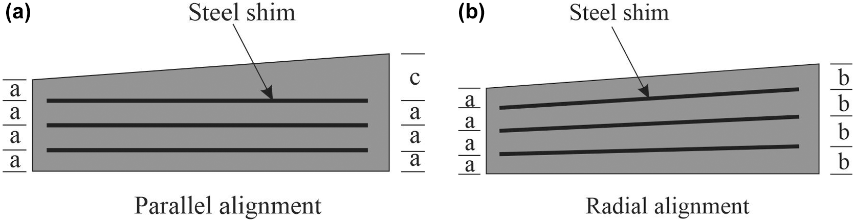
Steel shim alignments: (a) Parallel and (b) Radial ( 9 ).

Tapered bearing pad configuration using tapered shim ( 10 ).
In this present study, tapered bearing pads with different slopes were manufactured by modifying shim orientation and elastomer layer thicknesses of standard flat elastomeric bearing pads. The elastomer layer thicknesses were modified as per current manufacturing practices. Tapered pads and corresponding flat pads were tested to determine shear stiffness values by using an experimental test device that was designed and fabricated specifically for this study. This test device was designed to maintain a constant axial force while simultaneously imposing multiple cycles of shear displacement to the pad. A key objective was to evaluate the effect of slope on the shear stiffness of bearing pads. Note that other design checks required by AASHTO were not evaluated in this study. Test procedures for determining shear stiffness followed those described in ASTM D4014–03 Annex A1 and in the Florida Method 5-598 of Test for Evaluation of Bearing Pads (11, 12). Shear stiffness data collected for flat and tapered pads were then compared to quantify the effect of taper on shear stiffness of the pads.
Physical Description of Pads
Tapered pads used in testing were developed by modifying elastomer thicknesses and shim orientation of standard flat pads. In Florida, various standard flat pad types are available for use in bridge construction ( 13 ). Standard pads are labeled alphabetically (A, B, C, D, through K) and vary in relation to parameters including plan dimensions, thickness, shear modulus, number of shims, and load-carrying capacity. To evaluate the effect of taper on shear stiffness of pads with widely ranging parameters and to optimize this study, types E, F, and K (Table 1) were selected. After selection, tapered versions of pad types E, F, and K were developed.
Standard Bearing Pad Types Selected for Testing ( 13 )
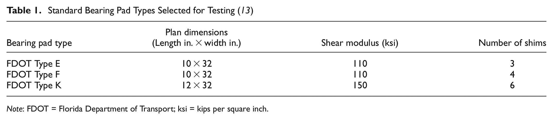
Note: FDOT = Florida Department of Transport; ksi = kips per square inch.
Three bearing pad manufacturers were contacted in relation to fabrication of tapered bearing pads. Each manufacturer responded that taper in pads can be introduced by varying pad thickness from end to end of the pad in multiples of 1/8 in. or 1/16 in.; manufacturers indicated a preference for 1/8 in. The manufacturers also mentioned that multiple layers of neoprene can be varied to create the desired tapered. Bearing pads that were used in the experimental program were able to be fabricated in accordance with AASHTO M251 and FDOT fabrication tolerances ( 14 , 15 ). Based on the earlier work of Muscarella and Yura, as well as discussions with current manufacturers of bearing pads, it was determined that taper could be incorporated into bearing geometry by changing the thickness of the pads in increments (N) of 1/8 in. (Figure 6) ( 9 ). Accordingly, tapered pads in this research were produced by incorporating taper in flat bearing pads along the length by changing bearing pad thickness in multiples of 1/8 in. such that the average thickness of each tapered pad was the same as the thickness of the original flat pad. Steel shims were aligned parallel to the bottom pad surface, except for the top shim which was inclined such that the elastomer thickness above and below the top shim was equal at any section transverse to the slope (Figure 6).
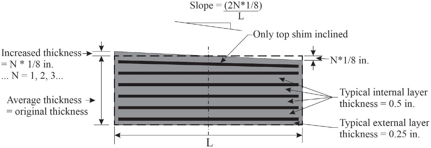
Bearing pad slope and shim configuration.
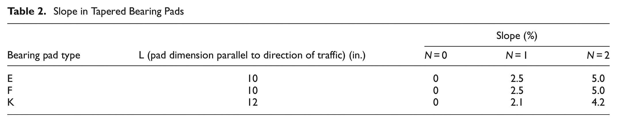
Proposed Guidelines for Pedestrian Facilities in the Public Right-of-Way, section R302.5, specifies a maximum slope of 5% for pedestrian access routes on highways ( 16 ). Further, Muscarella and Yura recommended that taper be limited to a maximum of 5% ( 9 ). Accordingly, for the present study, FDOT standard (flat) bearing pad types E, F, and K were modified to incorporate slopes with up to two increments (N) of 1/8 in. (maximum slope of 5%) as shown in Table 2. In the following text, each variation of pad is assigned a name of the form “pad type-slope%.” For example, FDOT pad type E with a taper slope of 2.5% is assigned the name “E-2.5%.” As per the material certificates provided by the manufacturer, the properties of the elastomer and steel shims satisfied the material-related requirements specified by Florida test method 5-598 and AASHTO M251 specification (12, 14).
Slope in Tapered Bearing Pads
Experimental Test Setup
An experimental test setup was designed to test a pair of matching bearing pads simultaneously and under different axial load levels. In general, the test setup consisted of a horizontally oriented hydraulic actuator connected to a wide flange (W) steel section support at one end and to a middle plate assembly at other end (Figure 7a). The test setup further consisted of a stack of two bearing pads (of identical type), each sandwiched between the middle plate assembly and two steel bearing plates. To simulate typical field conditions, the bearing pads, middle plate assembly, and steel plates were not mechanically connected, but instead relied solely on friction to transfer shear between the pads and plates. A vertically oriented hydraulic actuator was used to load the top bearing plate to compress the pads. A horizontal actuator—connected to the middle plate assembly—was used to shear the pads at the interface between the middle plate assembly and bearing pads. While shearing the pads, the axial load was maintained constant using a fine adjustment control on the vertical actuator operated by a technician. The axial load was maintained within approximately ±5 kip of the target load for each test. For tests involving tapered pads, the middle plate assembly was modified by inserting wedge plates with different slopes (Figure 7b). Four hollow square section (HSS) steel “arms” provided connections between the bearing plates (top and bottom) and the wide flange (W) section as shown in (Figure 7a). The assembly consisting of the four HSS sections and the horizontal actuator formed a self-reacting load frame in which the forces required to shear the pads remained internal to the load frame and did not generate horizontal reaction on the laboratory strong floor.
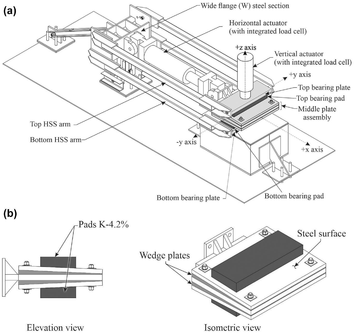
Test setup (configured for pad K-4.2%): (a) Isometric view and (b) Middle plate assembly.
The vertical elevations of the top and bottom HSS arms, along with the top and bottom bearing plates, were changed between tests to accommodate pads types with different thicknesses. The top and bottom arms had multiple connection points available on the wide flange section to accommodate for different pad types (Figure 8). The top arm was engaged in one hole at a time on the wide flange section to create a pinned connection, and the bottom arm was engaged in two holes at the same time to create a rigid connection. After connecting the arms to their respective connection points for a pad type, and applying axial load, the top arm and horizontal actuator rotated such that both the arms and the horizontal actuator were in horizontal alignment. At the same time, the top bearing plate and the middle plate assembly rotated to maintain the pads in horizontal alignment. The elevation of the bottom bearing plate was adjusted for different pad types by inserting steel plates of appropriate thicknesses underneath the plate.
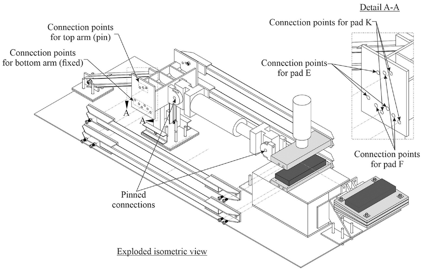
Exploded isometric view of the test setup (configured for pad K-4.2%).
Instrumentation involved the measurement of load and displacement at various locations. Load cells integrated into the vertical actuator (Enerpac, model RR-40018) and horizontal actuator (MTS, model 244.41) were used to measure axial and shear loads, respectively. Six laser displacement sensors (MTI Microtrak 3 Series, model LTS 300-200, labeled as “DX” in Figure 9) were used to measure shear displacements of the top and bottom bearing plates relative to the middle plate assembly, thus enabling determination of shear deformations in the bearing pads. Shear displacement of the top pad was calculated as the relative difference between the average displacement of the top plate and the average displacement of the middle plate. Similarly, shear displacement of the bottom pad was calculated as the relative difference between the average displacement of the bottom plate and average displacement of the middle plate.
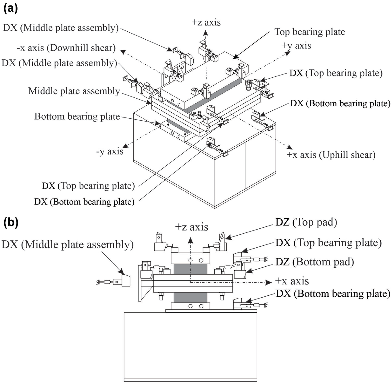
Laser sensors instrumentation plan: (a) Isometric view and (b) Elevation view.
Test Procedure
Each shear stiffness test was performed by shearing a stack of two identical pads at the interface with the middle plate assembly using the horizontal actuator. During each test, a pair of pads was shear loaded and released over six cycles in the negative shear direction, where the first five cycles of 0.7 shear strain were used to condition the pads, and the sixth cycle of 0.5 shear strain was used to determine the shear stiffness (Figure 10a). Note that, in this test setup, positive shear strain is the strain applied when the horizontal actuator piston was extended, and negative shear strain was produced when the piston was retracted. Select pairs of tapered bearing pads were also tested in the positive shear direction (Figure 10b) to investigate whether the direction of shear loading (and deformation) would result in differences of pad shear stiffness. The test procedure and selection of shear strain levels were performed in accordance with ASTM D4014–03 and Florida method 5-598 of Test for Evaluation of Bearing Pads ( 11 , 12 ). As per ASTM D4014–03, each cycle for testing shear stiffness was performed within a timeframe of 30 to 60 s ( 11 ). Figure 11 shows photos of pads K-0% and K-4.2% during shear testing.
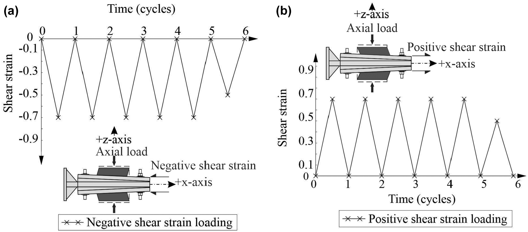
Shear strain loading and release cycles for shear stiffness testing: (a) Negative strain cycles and (b) Positive strain cycles.
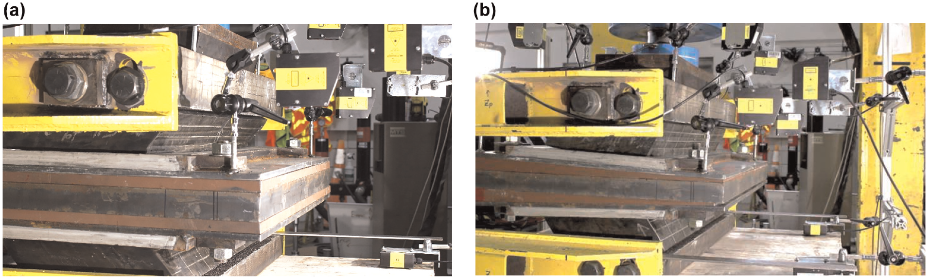
Pads under negative shear strain loading: (a) Pads K-0% and (b) Pads K-4.2%.
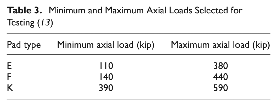
During the shear tests, a constant axial load was maintained on the pads by monitoring and adjusting the vertical actuator. A minimum and a maximum axial load level were established for each bearing pad type, where the minimum axial load represented dead load acting on the pads, and the maximum load represented the sum of dead and live loads on the pads. These axial load levels, shown in Table 3, were determined from the FDOT Instructions for Design Standards (IDS) Index no. 20510: Composite Elastomeric Bearing Pads - Prestressed Florida-I Beams ( 13 ). Shear stiffnesses were quantified at both minimum and maximum axial load levels.
Minimum and Maximum Axial Loads Selected for Testing ( 13 )
Shear Stiffness Results
Pad shear stiffness was determined as the linear curve fit (least square error) to the test data obtained from the last (sixth) shear strain loading cycle (Figure 12). As mentioned earlier, the first five shear strain cycles were used to condition the pads and remove the Mullin’s effect; data from these cycles were not used for shear stiffness analysis. Shear stiffness determined using a negative strain cycle was denoted the “downhill” shear stiffness, and stiffness determined using a positive strain cycle was denoted the “uphill” shear stiffness. These terms refer to the pad and girder combination presented in Figure 13 where girder motion to the left would be downhill shear, and girder motion to the right would be uphill shear. Shear stiffnesses were quantified for all tapered pads and corresponding flat pads. In Table 4, shear stiffness values are divided by (i.e., normalized with respect to) the downhill shear stiffness of the corresponding flat pad at each axial load level (denoted as the normalizing shear stiffness). The average difference between measured and theoretical shear stiffness for all pads was about 20%. The theoretical stiffness was calculated as (
Normalized Shear Stiffness Data
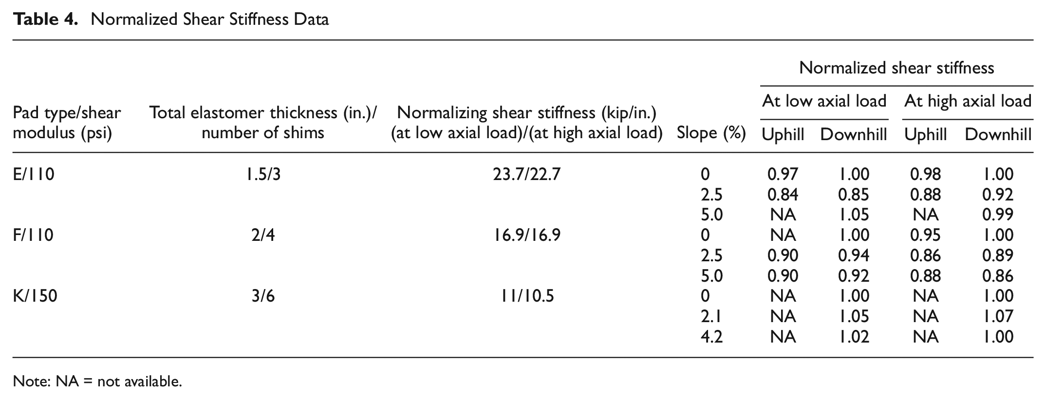
Note: NA = not available.
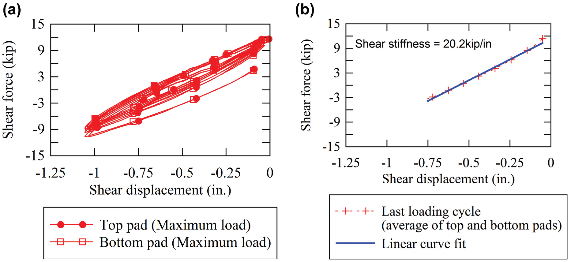
Example of processing data for downhill shear stiffness determination (pad E-2.50%): (a) original data and (b) data of only the last loading cycle and linear curve fit.
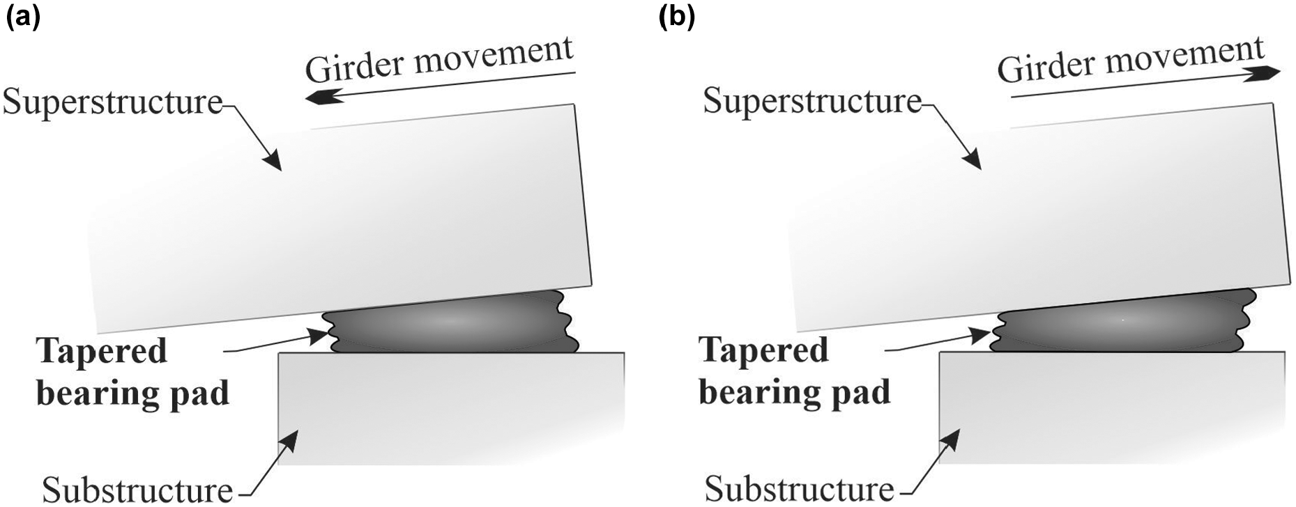
Shear direction: (a) Downhill and (b) Uphill.
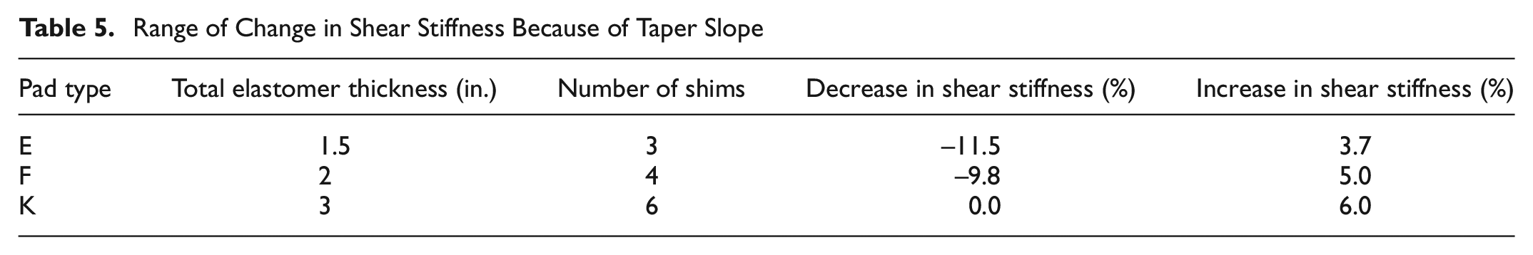
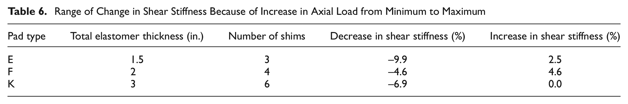
Figure 14 shows that the shear stiffness of pads, with taper slope between 0% and 5%, did not change significantly with the introduction of slope. Table 5 shows that the range of difference in shear stiffness of tapered pads compared with corresponding flat pads was between −11.5% and +6%. For tapered pads, the uphill shear stiffnesses were, in general, found to be smaller than the downhill shear stiffnesses, but differing by less than 4%. In Table 6, maximum decreases and increases in shear stiffness, produced by increase in axial load from minimum to maximum, are summarized. The minimum and maximum loads for each pad type are provided in Table 3. The results in Table 6 indicate that the shear stiffnesses of bearing pads at high axial load level did not differ significantly from the corresponding shear stiffnesses at low axial load level for each pad type tested. As expected, the shear stiffnesses of pads, both flat and tapered, were found to decrease as the average elastomer thickness increased. For example, shear stiffness decreased by a factor of 2.0 as the total elastomer thickness increased by a factor of 2.0 from pad E-0% to pad K-0%. Bearing pads were dissected after testing to inspect for delamination or rupture of steel shims. On dissection, no delamination was found (for example see Figure 15).
Range of Change in Shear Stiffness Because of Taper Slope
Range of Change in Shear Stiffness Because of Increase in Axial Load from Minimum to Maximum
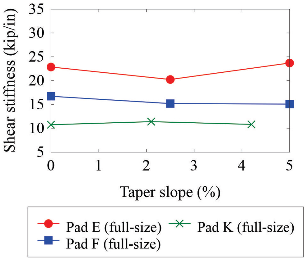
Effect of taper slope on shear stiffness.
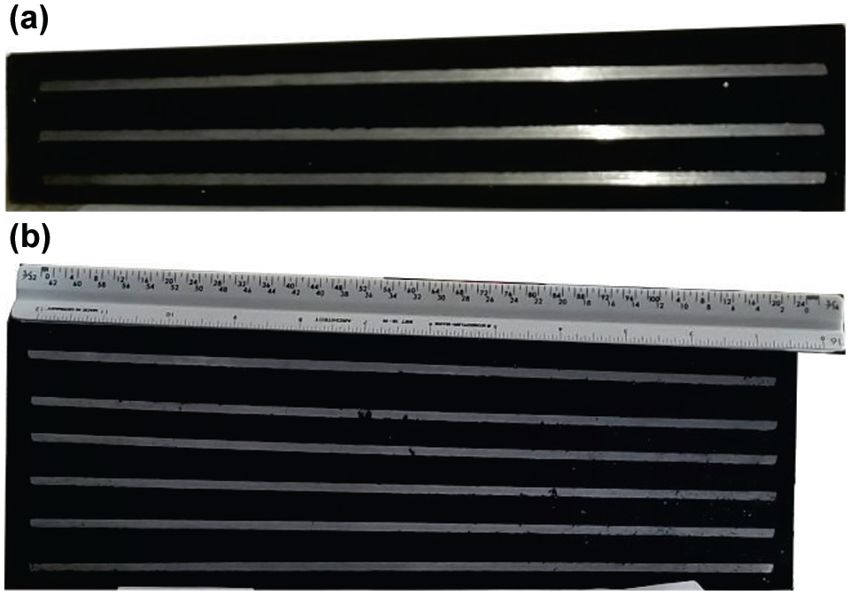
Dissected cross-sections of bearing pads: (a) E-5% and (b) K-4.2%.
Summary and Conclusions
Designers utilize shear stiffness values of bearing pads in the bridge design process, and limited guidelines are available for the determination of tapered pad shear stiffness. The goal of this study was, therefore, to quantify shear stiffnesses of flat and tapered bearing pads, and to determine the effect of taper on the shear stiffness of pads. An experimental test setup was designed and built to determine shear stiffnesses of flat and tapered pads with varying taper slope, total elastomer thickness, and plan dimensions under different axial load levels.
A key finding from this experimental study was that shear stiffness of tapered pads, with slope between 0% and 5%, was not significantly influenced by the taper angle or the direction of shear deformation. The shear stiffness of tapered pads was found to vary between −11.5% and +6% of the shear stiffness of corresponding flat pads. For tapered pads, the uphill shear stiffnesses were, in general, found to be smaller than the downhill shear stiffnesses, but differing by less than 4%. The results also indicated that the shear stiffnesses of bearing pads at high axial load level did not differ significantly from the corresponding shear stiffnesses at low axial load level for each type of pad. Therefore, the shear stiffness of a tapered pad may be estimated to differ by no more than approximately ±10% relative to the shear stiffness of the corresponding flat pad. Note that other design checks required by AASHTO, and the effects of temperature change, or cyclic and dynamic loading on shear stiffness, were not evaluated in this paper. Further, axial and rotational stiffnesses of tapered pads are outside the scope of this paper. Nevertheless, the tapered pads investigated in this paper performed similarly to flat pads in shear, with no observed delamination of the steel shim plates.
Footnotes
Author Contributions
The authors confirm contribution to the paper as follows: study conception and design: S. Patil, G. Consolazio, H. Hamilton; data collection: S. Patil; analysis and interpretation of results: S. Patil, G. Consolazio, H. Hamilton; draft manuscript preparation: S. Patil, G. Consolazio, H. Hamilton. All authors reviewed the results and approved the final version of the manuscript.
Declaration of Conflicting Interests
The author(s) declared no potential conflicts of interest with respect to the research, authorship, and/or publication of this article.
Funding
The author(s) disclosed receipt of the following financial support for the research, authorship, and/or publication of this article: Funding for the work presented in this paper was provided by the Florida Department of Transportation (FDOT) under contract BDV31 977-95.
The opinions, findings and conclusions expressed in this publication are those of the author(s) and not necessarily those of the Florida Department of Transportation or the U.S. Department of Transportation.