
Abstract
In the United States, highway bridge design practice is based on the LRFD method developed by AASHTO. In AASHTO LRFD, which is based on the concept of limit states, the effect of foundation movements on structural elements is expressed as a force effect rather than a geotechnical resistance. In fact, all design codes worldwide recognize this observation by including a representation of structural effects of foundation movements as a force. AASHTO LRFD uses the designation “SE” for the geotechnical demands to be considered. An associated load factor, γ SE , is specified for each load combination where SE is applicable. The product of γ SE and SE is the factored demand, or factored force. The structural effect of foundation movements is manifested in the form of additional force effects such as induced torques, moments, and shears in a bridge structure that can lead to adverse consequences such as cracking. In AASHTO LRFD, the SE load factor occurs in four out of the five load combinations for Strength Limit State and three out of the four load combinations for Service Limit State. This paper presents a study that explores the structural considerations and implications related to use of SE load factor and the effects of foundation movements in AASHTO LRFD.
In the United States, highway bridge design practice is based on the LRFD method developed by AASHTO. In AASHTO LRFD ( 1 ), which is based on the concept of limit states, the effect of foundation movements on structural elements is expressed as a force effect rather than a geotechnical resistance. In fact, all design codes worldwide recognize this observation by including a representation of structural effects of foundation movements as a force. AASHTO LRFD uses the designation “SE” for the geotechnical demands to be considered. An associated load factor, γ SE , is specified for each load combination where SE is applicable. The product of γ SE and SE is the factored demand, or factored force. The structural effect of foundation movements is manifested in the form of additional force effects such as induced torques, moments, and shears in a bridge structure that can lead to adverse consequences such as cracking. In AASHTO LRFD, γ SE occurs in four out of the five load combinations for Strength Limit State and three out of the four load combinations for Service Limit State.
In the 8th Edition of AASHTO LRFD (“2017 provisions” in this paper) and all previous editions of AASHTO LRFD, γ SE = 1.00 is used regardless of the type of foundation movement and the method used to predict the value of the movement. To assess the validity of this provision, a reliability-based procedure for calibrating γ SE based on consideration of structural limit states was developed during the Second Strategic Highway Research Program (SHRP2) Project R19B ( 2 ). Work during Project R19B examined the uncertainty in predicted settlements from various analytical methods and developed procedures to calibrate γ SE values for different methods commonly used by bridge designers to predict foundation movements. Calibrated γ SE values based on Project R19B procedures are included in the 9th Edition of AASHTO LRFD issued in 2020 (“2020 provisions” in this paper).
Under the 2017 provisions most designers predict total foundation movements assuming the foundations support the loads on the completed structure. This implies a scenario in which a bridge structure is instantaneously set into place and all the loads are applied at the same time. Of course, foundation movements occur as the structure is assembled, and loads are applied sequentially during various construction stages. Thus, foundation movements predicted to occur before placement of the superstructure may not be relevant to the design or performance of the superstructure. For example, depending on the type of superstructure and the construction sequence implemented, the immediate settlement between the construction stage at which the stresses in the superstructure elements are affected by differential settlements and the end-of-construction can be between 25% and 75% of the total settlement (2–4). Thus, the predicted relevant settlement that may affect a bridge structure can be much less than the predicted total settlement. Consideration of the construction sequence to determine the relevant foundation movements is referenced as the construction-point concept (2–4). To ensure more realistic designs, the 2020 provisions recommend use of the construction-point concept. Guidance for consideration of long-term (consolidation) settlements is included in Samtani and Kulicki ( 3 ).
Need for Study
As part of the review and balloting processes for the 2020 provisions by AASHTO T-15 (Substructures and Retaining Walls) and T-5 (Loads and Load Distribution) technical committees, the following items were noted:
Bridge designers do not consider foundation settlements in a consistent manner in the bridge design process or in accordance with 2017 provisions. The need to demonstrate correct procedures for consideration of settlements in bridge design process was identified and acknowledged.
Most bridge designers who did consider settlement in bridge design tended to limit settlements to arbitrary and small values of settlement, for example, less than 0.5 or 1 in. Assumptions like this can result in costlier and inefficient foundation systems and in some cases necessitate un-needed ground improvement.
The effect of proposed γ SE values in conjunction with the implementation of the construction-point concept on the bridge design process needed to be assessed by the design team.
To address these items, the need for a study with the following goals was identified: (a) demonstration of the correct implementation of foundation movements in bridge design process, (b) evaluation of the structural implications of the 2020 provisions on the bridge design process, and (c) evaluation of the effects of using other values of γ SE to help understand the potential impacts of a range of factors that could come from future regional calibrations.
Data and Scope for Study
To achieve the study goals, data from several continuous span steel girder constructed bridges were collected and evaluated for a range of foundation settlements and γ SE values. Table 1 provides characteristics of the bridges that were evaluated ( 3 ):
Bridge Characteristics ( 3 )
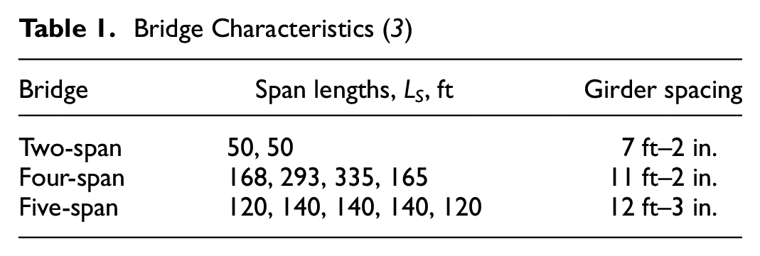
Thus, three bridge configurations with short, medium, and long spans and different girder spacings were evaluated. Structural computations for incorporation of calibrated values of a range of foundation settlements and γ SE values are demonstrated in this paper using the four-span bridge example. The computations for the two-span and five-span bridges were performed in a similar manner ( 3 ).
Tables 2 and 3 provide the unfactored moment and unfactored shear values, respectively, for a typical interior girder based on dead load (DL), live load (LL), and unit (1 in.) settlement at each of the supports for the four-span bridge example. The top row in these two tables gives the force effect (moment and shear) values from the DL only. The second row, and the two subset rows labeled +ve (for positive) and −ve (for negative), provides values of force effects generated by LL. Following the common structural convention, the positive moment causes tension on the bottom of a flexural member and the negative moment causes tension of the top. Maximum +ve moments caused by LL typically occur within the span, whereas maximum −ve moments caused by LL occur at or near a support element (e.g., pier). Values of maximum +ve moment and minimum (i.e., maximum −ve) within each span and at each intermediate support are shown in Table 2. These locations along the bridge were selected for illustration purposes because they are, or are near, the locations of peak structural demands in most bridges. In an actual design the effect of settlement would be evaluated at all design points along the length of the bridge just as would be done for all other structural demands. Table 3 provides values of maximum shear at each abutment and maximum and minimum shear on both sides of intermediate supports. The last four rows in Tables 2 and 3 show the values of induced force effects when individual substructure elements experience foundation settlement of 1 in. These values were developed by imposing a 1 in. downward movement at one support at a time and noting its effect at the locations noted in the tables. The term “unfactored” indicates that a nominal value or a value of 1.00 is used for the load factor for the considered load type. The moment and shear values were developed using of a commercially available bridge analysis program ( 3 ).
Unfactored Moment Values ( 3 )
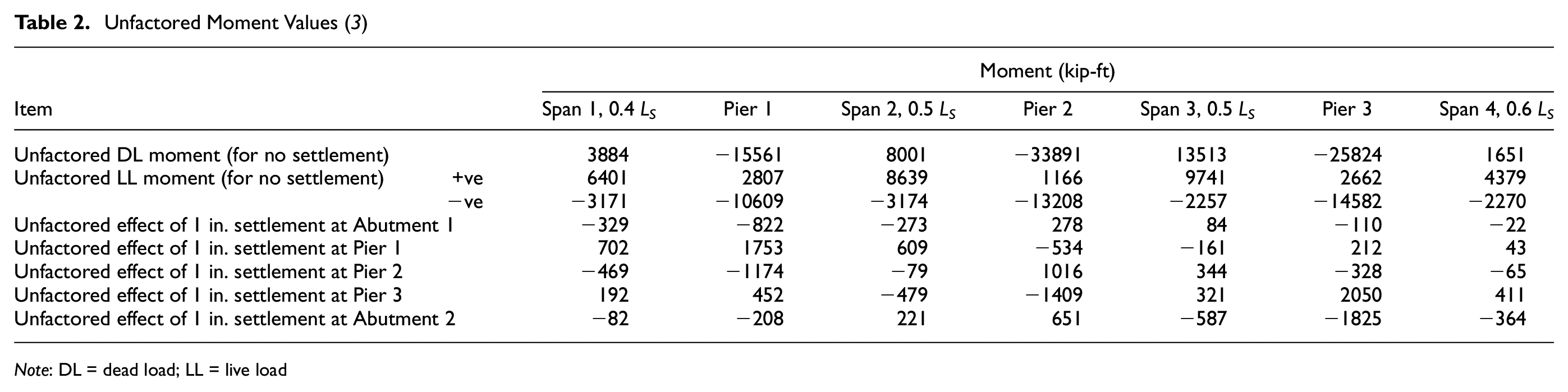
Note: DL = dead load; LL = live load
Unfactored Shear Values ( 3 )
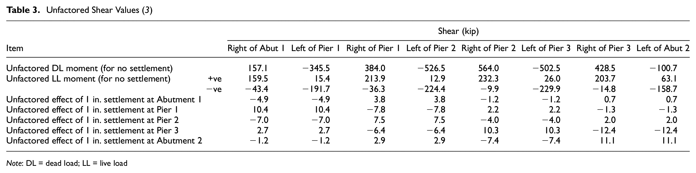
Note: DL = dead load; LL = live load
Values of γ SE adopted by AASHTO for the 2020 provisions range from 1.00 to 1.40. As part of the study to investigate the effects of foundation settlements on the bridge design process, AASHTO decided to consider values of γ SE = 1.00, 1.25, and 1.75 to evaluate the structural implications on the bridge design practice based on γ SE = 1.00 in 2017 and all previous editions of the AASHTO LRFD provisions. The value of γ SE = 1.75 was chosen to explore the effect of a large increase in γ SE in bridge design and to account for any future values of γ SE which may be in the range of 1.75 based on regional (i.e., local) calibrations that are encouraged by AASHTO and FHWA ( 3 ). The value of γ SE = 1.25 which was developed for a regional database from the northeast United States (2–4) was chosen as an intermediate value. Thus, the examples to follow have more variations than would be required for a typical design. In addition, the parametric study involved evaluation of the following:
Use total settlement, St, because it is the value selected by most designers based on the 2017 provisions. Total settlements ranging from 0.50 in to 4.80 in. were considered
Use total relevant settlement, Str, which is based on the construction-point concept, to demonstrate the concept’s potential as a rational, cost-saving alternative to using St for design.
The wide range of total settlement values coupled with the wide range of γ SE values explore most of the possibilities that might be encountered in practice. The two-span and five-span bridge configurations were also evaluated in a similar manner ( 3 ).
Settlement Values for Four-Span Bridge
In Table 4, which presents the settlement data for the four-span bridge, the St values represent the predicted unfactored total settlement at each support element. The term “unfactored” indicates a value of γ SE = 1.00 was used as recommended in the 2017 provisions. The Str values represent the unfactored estimated total relevant settlement at each of the support elements. Although values of Str can range from 25% to 75% of St, Str = 50% was used for this example. The SFR values represent the factored relevant settlements at each support element using the values of γ SE = 1.25 and γ SE = 1.75. These values are computed by multiplying the Str values by the applicable γ SE value. For γ SE = 1.00, SFR = Str.
Unfactored and Factored Total and Relevant Settlements ( 3 )
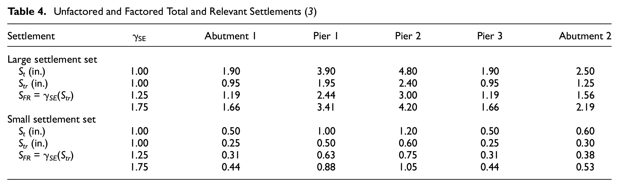
For illustration purposes only, two sets of settlement values were evaluated for the four-span bridge example. These sets are here referred to as “large settlement” and “small settlement.”Table 4 presents the values of St, Str, and SFR, values for both sets. Figure 1 shows the settlement profiles for the two sets. In both sets the maximum settlement occurs at Pier 2. The data in Tables 2 and 3 indicate that for this specific four-span bridge example larger values of moments and shears occur in spans 2 and 3 and at Pier 2. This is not necessarily the case of all bridges, as the values of settlement and the induced moments and shears will vary based on specific subsurface conditions, loads, and bridge configurations.
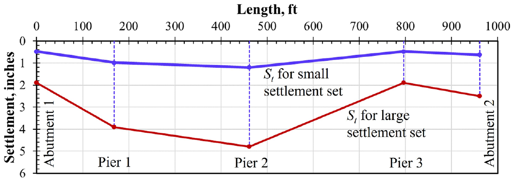
Profiles of total settlement (St) for small and large settlement sets.
AASHTO Provisions for Consideration of Settlements
AASHTO LRFD Article 3.12.6 states “Force effects due to extreme values of differential settlement among substructures and within individual substructure units shall be considered.” The commentary to this article states “Force effects due to settlement may be reduced by considering creep. Analysis for the load combinations in Tables 3.4.1-1 and 3.1.4-2 which include settlement should be repeated for settlement of each possible substructure unit settling individually, as well as combinations of substructure units settling, that could create critical force effects in the structure.” The word “creep” is in the context of structural creep and not in the sense of soil consolidation. The use of words such as “extreme values of differential settlement” and “critical force effects” reflect the concern of code writers that some foundation units may settle less than predicted, or even undergo no settlement. In applying these provisions, designers must recognize that γ
SE
addresses uncertainty in the foundation movement at a given support location and for a certain model for predicting movement. It
Further, AASHTO LRFD Article 3.4.1 states “Load combinations which include settlement shall also be applied without settlement.” The purpose of this provision is to alert the designer to make sure that the force effect owing to settlement must not be used to reduce the permanent force effects.
The effects of these provisions must be considered in a two-fold manner (
4
): geometric and structural. The geometric effect is evaluated through the change in grade using the concept of angular distortion. The structural effect is evaluated through the values of the additional force effects: induced torque, moment, and shear caused by settlement. In both cases, however, as noted above, consideration of “extreme values of differential settlement” and evaluation of “critical force effects”
Assume that the actual (measured) settlement of any support element could be as large as the predicted factored relevant settlement value, SFR, calculated by using a given method.
Assume that the actual (measured) settlement of the adjacent support element could be less, taken as zero in the limit, instead of the predicted factored relevant settlement value, SFR, calculated by using the same given method.
This approach is referred to as the “SFR–0” concept where SFR represents the predicted factored relevant settlement at one support of a span and the value of “0” represents zero settlement at an adjacent support, that is, the limiting small value. Because one support is assumed to have zero settlement, the resulting differential settlement becomes the extreme value as required by AASHTO. This approach helps eliminate the additional uncertainty associated with differential settlement ( 5 ). Thus, after using the SFR–0 approach, the only uncertainty remaining is that associated with the settlement values at each of the support elements used to compute the differential settlement and this uncertainty is addressed by γ SE ( 5 ). The choice of a null settlement in the SFR–0 approach is a practical expedient but may be judged to be excessive at sites where little variation from predicted settlement is expected. If a variation in the SFR–0 approach is used procedures to estimate the additional uncertainty in differential settlement are provided by Samtani and Kulicki ( 5 ). In any case, two modes of differential settlement within any span must be evaluated. In Mode 1 the left support is assumed to have zero settlement, whereas in Mode 2 the right support is assumed to have zero settlement. The bridge design process must explore all viable deformed shapes by evaluating these two modes for all bridge spans. This approach also helps create the extreme values of differential settlement and evaluate the critical force effects as required by 2017 and 2020 provisions.
Geometric Effects
Differential settlement leads to a change in grade which can be expressed as angular distortion, Ad. In the longitudinal direction of the bridge Ad = Δ S /LS, where Δ S is the differential settlement between adjacent support elements and LS is the distance between supports (span length). Table 5 shows the values of the factored angular distortion, AdF = Δ SFR /LS, using the SFR–0 concept where Δ SFR is the differential settlement based on factored relevant settlements.
Factored Angular Relevant Distortions to Check for Geometric Effects ( 3 )
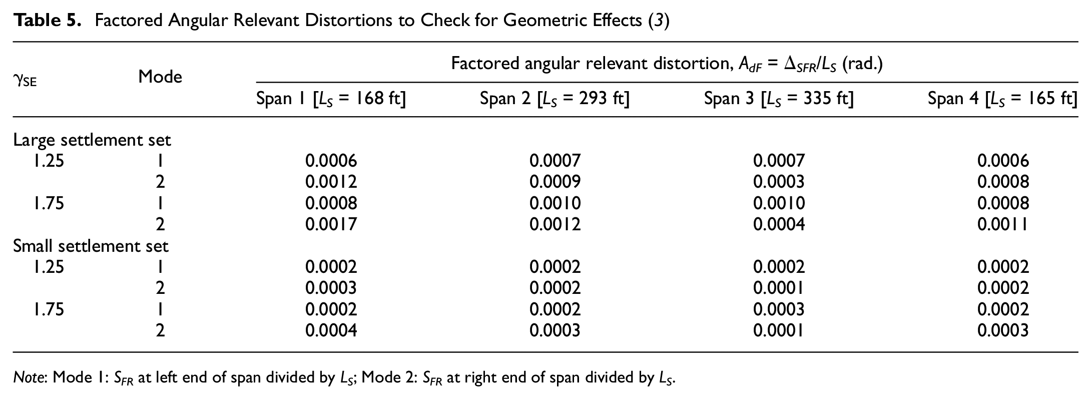
The values of AdF and SFR are compared with owner-specified criteria for tolerable movements to evaluate the geometric effects. The value of AdF should be evaluated by comparison with acceptable angular distortion criteria based on considerations of drainage, tolerances of appurtenances attached to the bridge, and so forth. For example, permissible angular distortion criteria are provided in Article 10.5.2 of 2017 provisions, which permits an angular distortion of 0.004 for multiple-span (continuous span) bridges and 0.008 for simple span bridges. Newer criteria in Article 10.5.2 of the 2020 provisions based on Project 12-103 of NCHRP ( 6 ) can also be used. Similarly, the value of SFR should be evaluated by comparison with tolerable values at abutment interfaces which can lead to creation of the ubiquitous “bump at the end of a bridge,” reduction in vertical clearance under a bridge, and/or the detrimental effect on the joints.
If the AdF and SFR are found to be unacceptable based on an evaluation of geometric effects, the bridge structure should be reproportioned and reevaluated. The bridge analysis is continued to evaluate structural effects if AdF and SFR are found to be acceptable. In the case of the four-span bridge example, the values in Table 5 are much smaller than those noted in Article 10.5.2 of 2017 provisions, so they are deemed acceptable.
Structural Effects
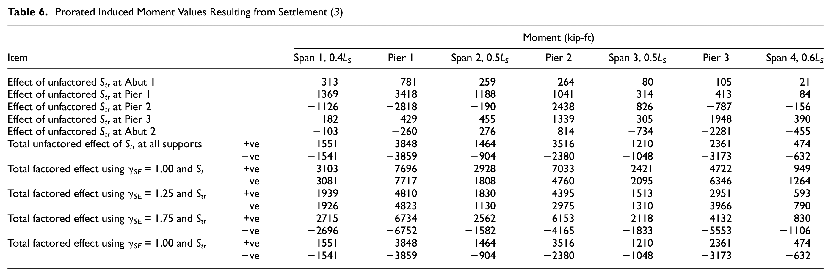
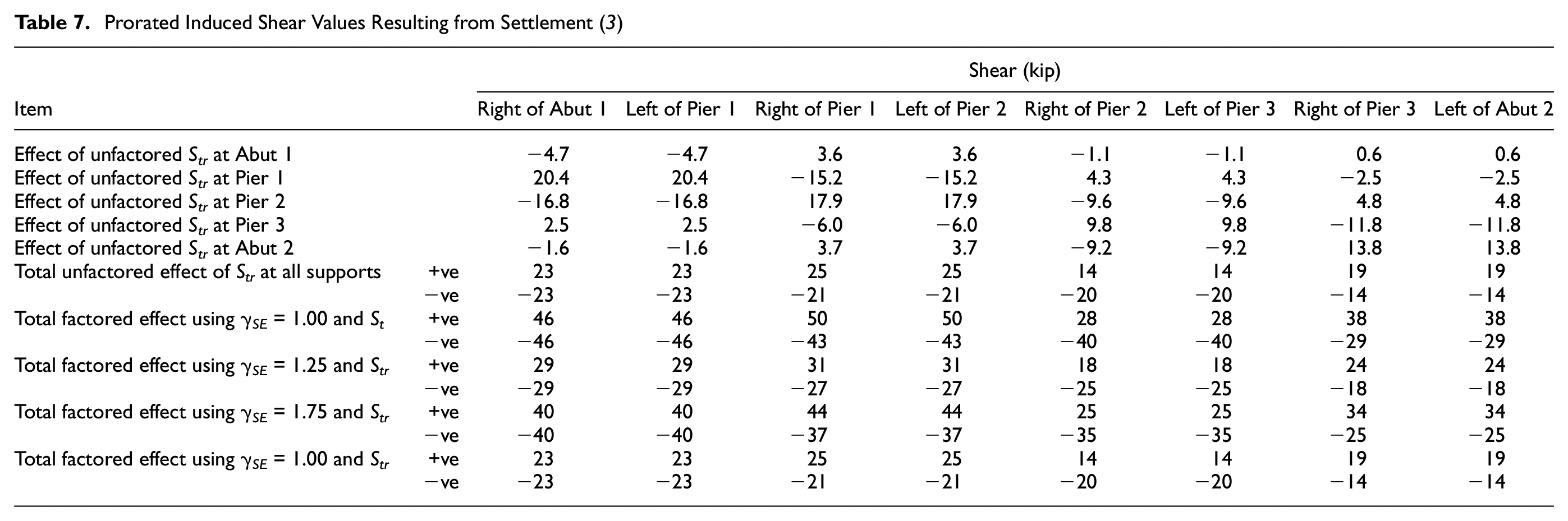
Most bridges are designed using a linear (elastic) approach, where sets of loads acting simultaneously can be evaluated by superimposing (adding) the loads, force effects, or movements at the point of interest. In this approach, the induced force effects resulting from foundation movements can be prorated (scaled) and superimposed on the force effects from primary loads such as DL and LL. Thus, the unfactored effect of 1 in. (i.e., unit) settlement at each of the support elements noted in Tables 2 and 3 can be prorated for the settlement value of interest by adding the resulting force effects to the primary force effects. Using this process Tables 6 and 7 show the prorated induced moments and shears, respectively, resulting from settlement.
Prorated Induced Moment Values Resulting from Settlement ( 3 )
Prorated Induced Shear Values Resulting from Settlement ( 3 )
Computations in the Tables 6 and 7 are demonstrated below with respect to Pier 1 in Table 6, which contains computations for induced moments using the large settlement data from Table 4 (values in Table 6 are rounded to the nearest whole number):
Effect of unfactored Str at Abutment 1: (0.95 in./1.00 in.)(−822 kip-ft) = −780.9 kip-ft.
Effect of unfactored Str at Pier 1: (1.95 in./1.00 in.)(1753 kip-ft) = 3418.3 kip-ft.
Effect of unfactored Str at Pier 2: (2.40 in./1.00 in.)(−1174 kip-ft) = −2817.6 kip-ft.
Effect of unfactored Str at Pier 3: (0.95 in./1.00 in.)(452 kip-ft) = 429.4 kip-ft.
Effect of unfactored Str at Abutment 2: (1.25 in./1.00 in.)(−208 kip-ft) = −260.0 kip-ft.
Total unfactored effect of Str at all contributing supports: +ve value: 3418.3 kip-ft + 429.4 kip-ft = 3847.7 kip-ft and −ve value: −780.9 kip-ft – 2817.6 kip-ft – 260.0 kip-ft = −3858.5 kip-ft.
Total factored effect of settlement using γ SE = 1.00 and St: +ve value: (3.90 in. /1.00 in.) (1753 kip-ft) (1.00) + (1.90 in./1.00 in.) (452 kip-ft) (1.00) = 7695.5 kip-ft. −ve value: (1.90 in./1.00 in.) (−822 kip-ft)(1.00) + (4.80 in. /1.00 in.) (−1174 kip-ft) (1.00) + (2.50 in. /1.00 in.) (−208 kip-ft) (1.00) = −7717.0 kip-ft.
Total factored effect of settlement using γ SE = 1.25 and Str: +ve value: (1.95 in. /1.00 in.) (1753 kip-ft) (1.25) + (0.95 in./1.00 in.) (452 kip-ft) (1.25) = 4809.7 kip-ft. −ve value: (0.95 in./1.00 in.) (−822 kip-ft)(1.25) + (2.40 in. /1.00 in.) (−1174 kip-ft) (1.25) + (1.25 in. /1.00 in.) (−208 kip-ft) (1.25) = −4823.1 kip-ft.
Total factored effect of settlement using γ SE = 1.75 and Str: +ve value: (1.95 in. /1.00 in.)(1753 kip-ft) (1.75) + (0.95 in./1.00 in.) (452 kip-ft) (1.75) = 6733.6 kip-ft. −ve value: (0.95 in./1.00 in.) (−822 kip-ft)(1.75) + (2.40 in. /1.00 in.) (−1174 kip-ft) (1.75) + (1.25 in. /1.00 in.) (−208 kip-ft) (1.75) = −6752.4 kip-ft.
Total factored effect of settlement using γ SE = 1.00 and Str (as γ SE = 1.00, these values are the same as those above for total unfactored effect of Str at all contributing supports): +ve value: 3418.3 kip-ft + 429.4 kip-ft = 3847.7 kip-ft. −ve value: −780.9 kip-ft – 2817.6 kip-ft – 260.0 kip-ft = −3858.5 kip-ft.
The numerical computations for induced moments at other supports in Table 6 as well as induced shear forces in Table 7 follow the same approach demonstrated previously for Pier 1. In these computations, the AASHTO provisions for considering settlements noted earlier were implemented in the calculations by summing all the positive and all the negative moments and shears at each point of interest in the four-span bridge example, thus enveloping all possibilities in a computationally efficient manner by avoiding non-controlling cases.
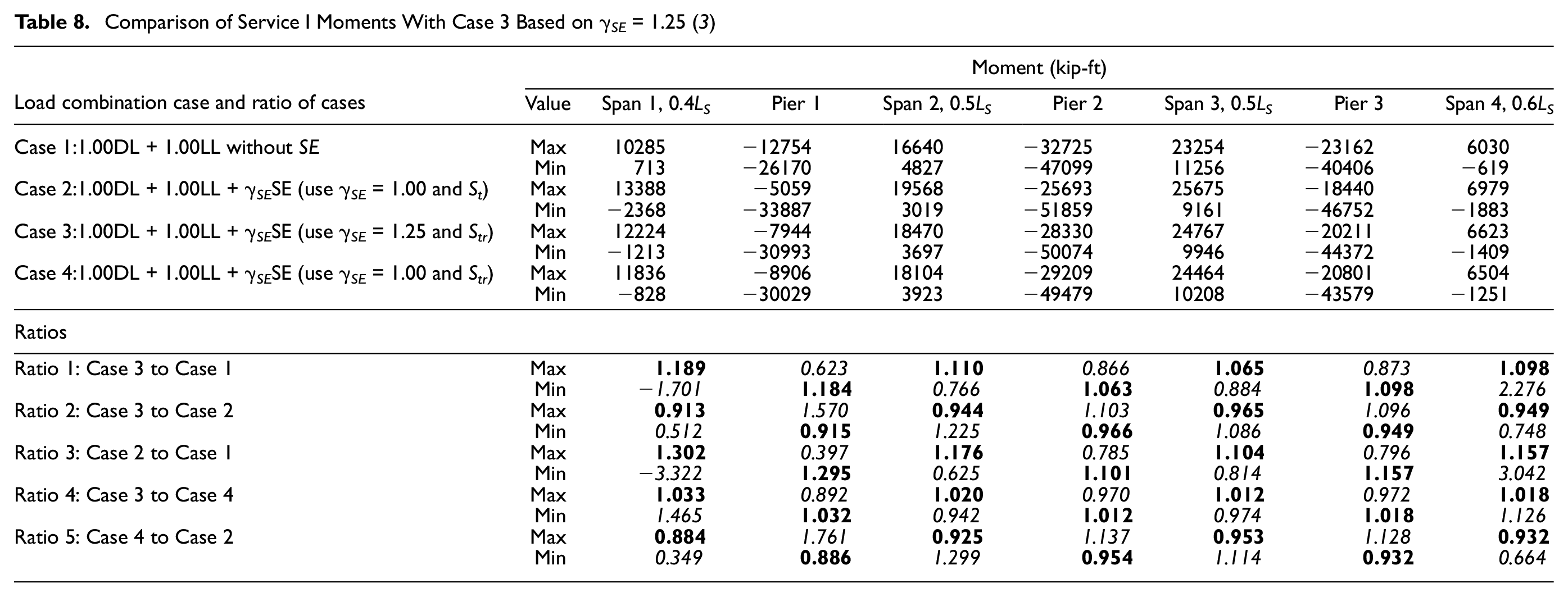
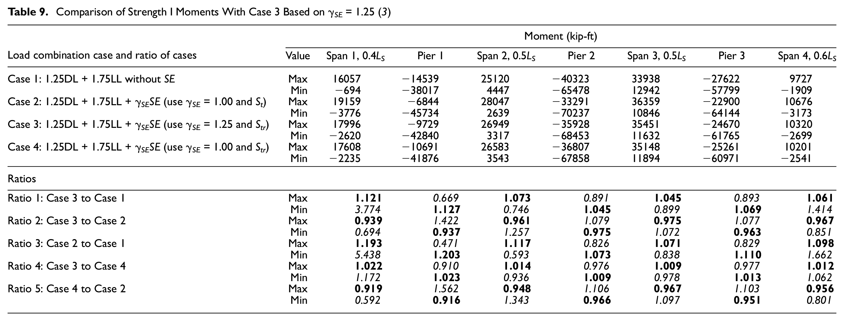
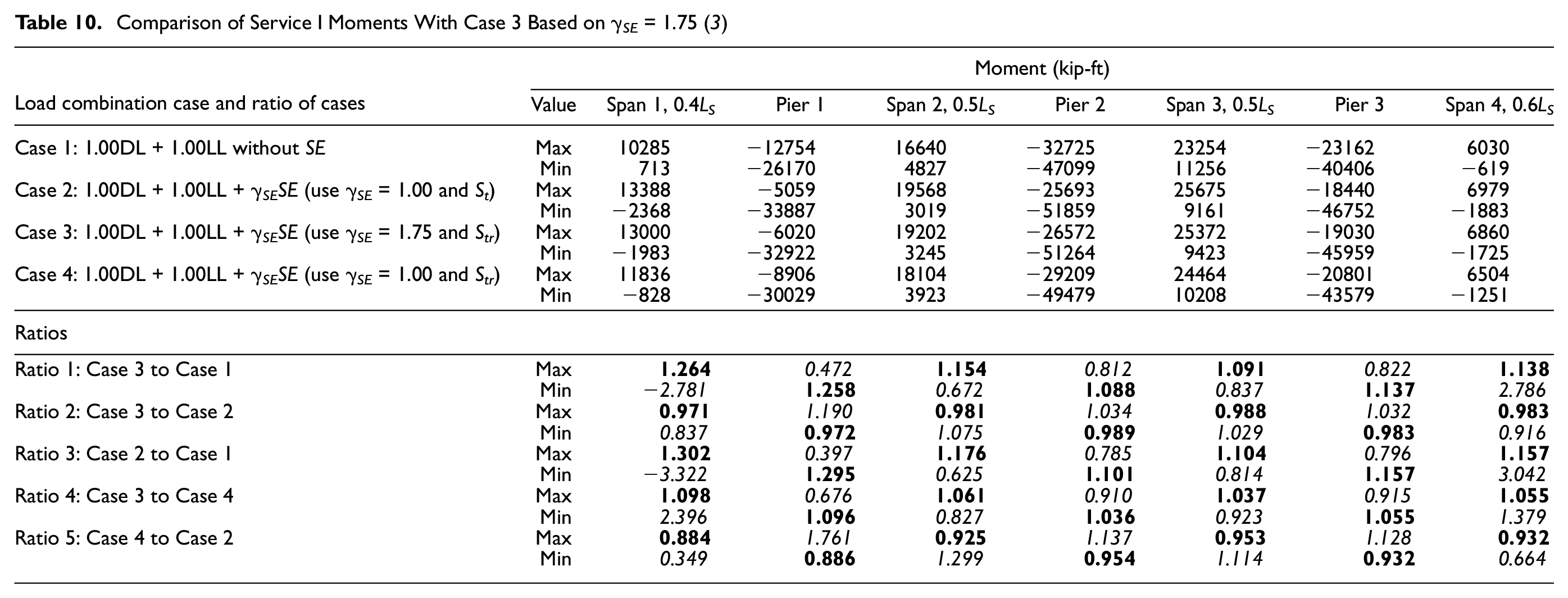
For comparison, four cases of Service I and Strength I load combinations were developed as follows in upper half of Tables 8 to 11.
Comparison of Service I Moments With Case 3 Based on γ SE = 1.25 ( 3 )
Comparison of Strength I Moments With Case 3 Based on γ SE = 1.25 ( 3 )
Comparison of Service I Moments With Case 3 Based on γ SE = 1.75 ( 3 )
Comparison of Strength I Moments With Case 3 Based on γ SE = 1.75 ( 3 )

Case 1: DL + LL with no settlement. This case represents designs performed without consideration of settlement. In this case, DL and LL are factored according to the load factors for Service I and Strength I load combinations.
Case 2: DL + LL with settlement using γ SE = 1.00. This case represents the 2017 provisions, where (a) DL and LL are factored according to the load factors for Service I and Strength I load combinations, and (b) the total settlement, St, with γ SE = 1.00 is used.
Case 3: DL + LL with settlement using the construction-point concept and method-specific γ SE value. This case represents the 2020 provisions, where (a) DL and LL are factored according to the load factors for Service I and Strength I load combinations, and (b) the relevant settlement, S tr , is used with γ SE value appropriate to the method used to estimate the settlement. As noted earlier, γ SE = 1.25 and 1.75 have been used to explore a range of γ SE values.
Case 4: This case is the same as Case 2 except that the total relevant settlement, Str, with γ SE = 1.00 is used. This case represents the practice in some Departments of Transportation and by some designers where total relevant settlements are used instead of total settlements.
In Tables 8 to 11, the rows labeled “Max” and “Min” the “Value” column refers to the maximum and minimum values of the total force effects. They are developed using the following two rules:
Rule 1: Combine the sum of the positive settlement contributions, factored as shown, with the DL and positive LL contributions to determine the maximum value of the force effect under consideration.
Rule 2: Combine the sum of the negative settlement contributions, factored as shown, with the DL and the negative live contributions to determine the minimum (i.e., maximum negative) value of the force effect under consideration.
This process of calculating positive and negative force effects (settlement and LL) and then adding those values to the DL force effects is a simple and practical way to implement the 2017 and previous editions of the AASHTO LRFD provisions for consideration of settlement discussed previously. The computations for induced shear forces were done in a similar manner ( 3 ).
The following five ratios (see lower half of Tables 8 to 11) were computed to evaluate the results:
Ratio 1: Case 3 to Case 1. This ratio compares the 2020 provisions using relevant settlement and γ SE ≥ 1.00 with the 2017 provisions without considering settlement. This ratio provides information concerning the level of potential under-design when the effect of settlement is not considered in the analysis.
Ratio 2: Case 3 to Case 2. This ratio compares the 2020 provisions using relevant settlement and γ SE ≥ 1.00 with 2017 provisions using total settlement and γ SE = 1.00.
Ratio 3: Case 2 to Case 1. This ratio compares the 2017 provisions using total settlement and γ SE = 1.00 with 2017 provisions without consideration of settlement. Like Ratio 1, this ratio provides information concerning the level of potential under-design when the effect of settlement is not considered in analysis using 2017 provisions.
Ratio 4: Case 3 to Case 4. This ratio compares the 2020 provisions using relevant settlement and γ SE ≥ 1.00 with 2017 provisions using relevant settlement and γ SE = 1.00.
Ratio 5: Case 4 to Case 2. This ratio compares the 2017 provisions using relevant settlement and γ SE = 1.00 with 2017 provisions using total settlement and γ SE = 1.00.
Because all results are compared for both the maximum and minimum values of the force effects, the ratios representing the controlling force effects are shown in bold large font typeface in the Tables 8 to 11. Conversely, all non-controlling force effects are italicized. Only the controlling values are carried forward in the design process. As stated previously, only selected locations along the bridge have been considered, for illustration purposes. Thus, the ratios in Tables 8 to 11 also apply only to those locations. It is possible that higher or lower ratios may be found at other locations along the bridge where the relative values of the demands from the various loads could be very different from the considered locations, for example near points of DL contraflexure.
Evaluation of Results
The results were evaluated based on comparisons between the four cases through ratios for both moment and shear values. The following general observations are made based on four-span bridge example presented in this paper and others studied by the authors ( 3 ):
Ratio 1 (Case 3 to Case 1) and Ratio 3 (Case 2 to Case 1), with respect to controlling value, are always greater than 1. This outcome is expected because Case 1 does not consider settlement, and the induced force effects attributable to settlement always add to the primary force effects caused by DL and LL. These ratios indicate the level of under-design that increases the possibility of occurrence of undesirable consequences such as cracking.
Ratio 2 (Case 3 to Case 2) is a direct comparison of the 2020 provisions with the 2017 provisions. In all instances in Tables 8 to 11, Ratio 2 for controlling force effects is less than 1. This indicates that even for γ SE values ranging up to 1.75, current bridge practice will not be affected with respect to change in member sizes for superstructure. This outcome results because the relevant settlements are considered for Case 3. Ratios less than 1 indicate the structure has reserve capacity so an opportunity for further optimization of structure exists. Although the whole structural system should be evaluated for improved economy, the focus of this paper is on foundation aspects. It may be possible to tolerate more foundation movement, which provides an opportunity to optimize the foundation configuration to realize cost savings. For example, a shallow foundation may be found viable instead of a deep foundation, or the size of a deep foundation may be reduced ( 4 ).
Exploring Ratio 2 further, the increase in total force effects for Case 3 (γ SE > 1.00) based on the 2020 provisions compared with Case 2 (γ SE = 1.00) based on the 2017 provisions are not in direct proportion to the value of the load factors used (i.e., γ SE = 1.25 or 1.75). For example, if γ SE = 1.25 is used then the total force effects do not increase by 25%. This result should be expected because the effect of the settlement is one of several components combined to determine the design load effect for a load combination. The exact value of the change in total force effects would be a function of many factors such as bridge superstructure type and configuration, substructure type, foundation type, and use of construction-point concept. In general, use of the construction-point concept reduces the effect of the settlement on the total force effects. In the example problems, the changes in total force effects did not significantly alter the controlling values for design. In such cases, consideration could be given to use of more efficient and cost-effective foundation types as well as other appropriate members of the bridge structure.
Depending on the magnitude of the differential settlement and the direction of the angular rotation in different spans, the values from Case 3 may be larger or smaller than the results from Case 1 or Case 2.
The four-span bridge example considered here illustrates that the difference in the controlling moments and shears is not significant regardless of whether Case 3 is compared with Case 1 or Case 2. Based on results from the two-span bridge with short spans ( 3 ), the difference in the controlling moments and shears may be more significant for shorter span bridges, depending on the stiffness and settlement values.
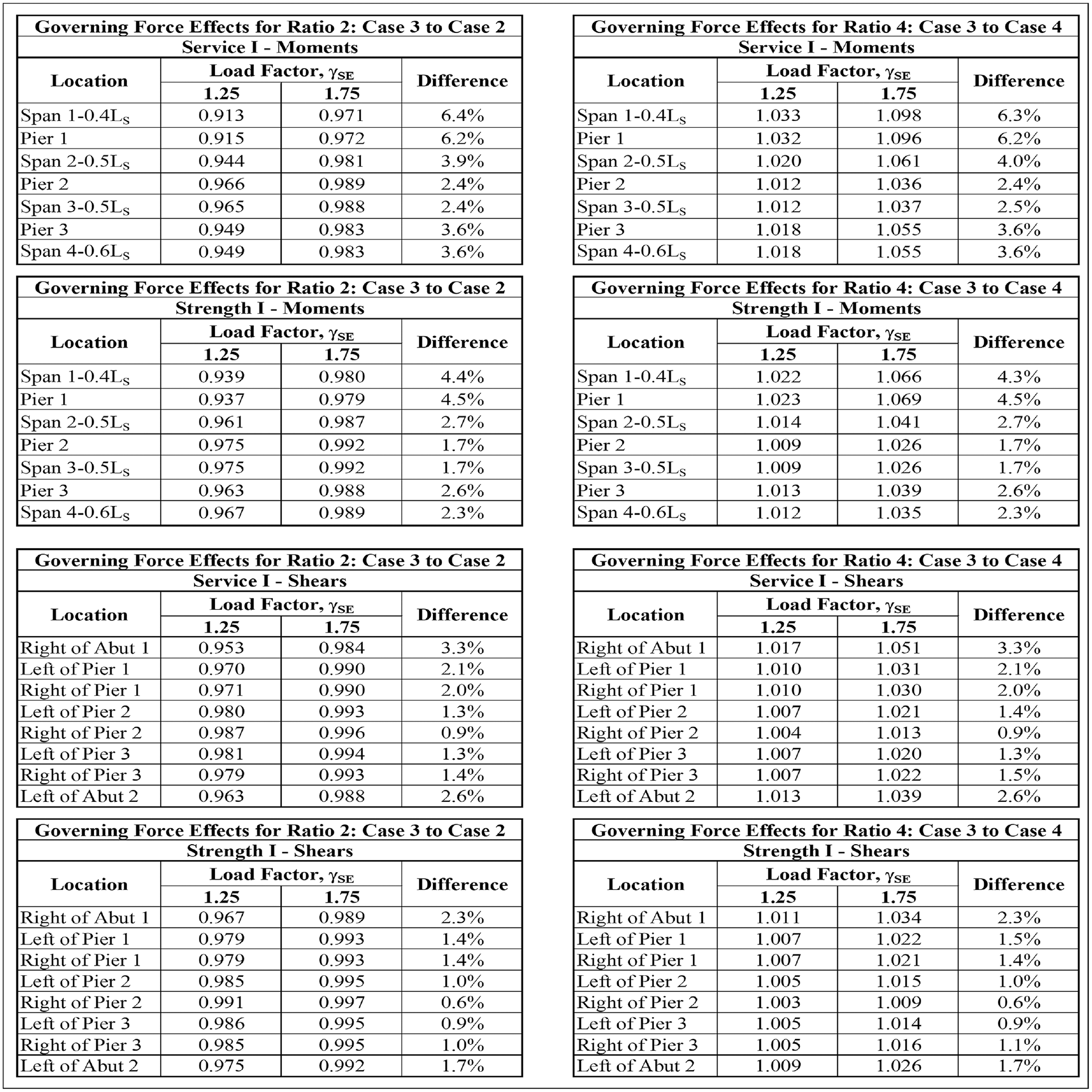
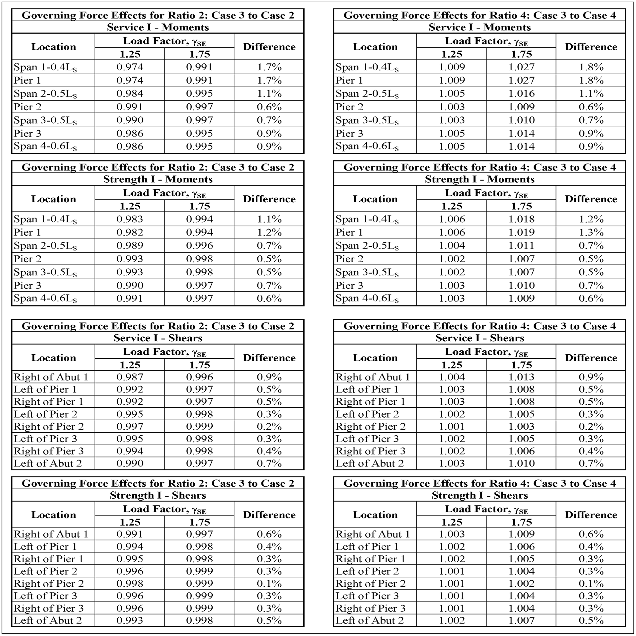
For the four-span bridge example, Figure 2 shows a summary of the results for the large settlement data set from Table 4 for both γ SE = 1.25 and γ SE = 1.75. Therefore, the effect of an increase in load factor of 40% (1.25 to 1.75) can be directly compared. In Figure 2, the results are tabulated as Ratio 2 (Case 3 to Case 2) and Ratio 4 (Case 3 to Case 4) for Service I moments, Strength I moments, Service I shears, and Strength I shears.
For a 40% increase in γ SE (i.e., 1.25 to 1.75), the evaluation of Ratio 2 and Ratio 4 indicates a maximum increase in induced force effects of 6.4% and 6.3%, respectively. Thus, for the specific four-span bridge example here, the controlling force effects for moments and shears did not change appreciably when the 2020 provisions were implemented. Comparable effects were noted for the two-span and five-span bridge examples studied by the authors ( 3 ).
For the four-span bridge example, Figure 3 shows a summary of the results for the small settlement data set from Table 4 for both γ SE = 1.25 and γ SE = 1.75. The results show that the effect of a 40% increase in load factor (i.e., 1.25 to 1.75) evaluated for the small settlement data set can be directly compared with those discussed previously for the large settlement data set. In Figure 3, the results are tabulated as Ratio 2 and Ratio 4 for Service I moments, Strength I moments, Service I shears, and Strength I shears.
For a 40% increase in γ SE (i.e., 1.25 to 1.75), the evaluation of Ratio 2 and Ratio 4 indicates a maximum increase in induced force effects of 1.7% and 1.8%, respectively. As expected, in comparison with the large settlement data in Figure 2, the effect of smaller settlements is reflected in the smaller values of the maximum increases. Similar trends should be expected in practice. For the specific four-span bridge example here, the controlling force effects for moments and shears did not change appreciably when the 2020 provisions were implemented. Comparable effects were noted for the two-span and five-span bridge examples studied by the authors ( 3 ).
For controlling forces effects, Ratio 5 in all instances in Tables 8 to 11 is less than 1. This outcome should be expected because Case 4 considers the relevant settlement that is less than the total settlement considered in Case 2.
Summary and Final Remarks
This paper presents the results of a study performed to evaluate the structural implications related to the use of calibrated γ SE load factor and relevant foundation movements in the AASHTO LRFD bridge design process. The key observations are:
Use of the construction-point concept with γ SE results in much smaller effects on controlling total moments and shears than would be indicated by the value of γ SE .
Even with the 40% increase in the value of γ SE prescribed in AASHTO LRFD (i.e., a change from 1.25 to 1.75) and using the construction-point concept, the difference in the controlling force effects is small.
The changes in the controlling force effects increase as the settlements increase and vice versa.
These key observations are expected because (i) within the overall AASHTO LRFD framework γ SE is just one of the many load factors in the Service and Strength Limit State load combinations, (ii) compared with the primary force effects attributable to DL and LL, the induced force effects resulting from settlement are much smaller in the specific examples studied, and (iii) the differential settlements have a direct and proportionate (scalable) influence on the induced force effects. Because of all these considerations, the effect of settlements on a bridge structure must always be evaluated for all projects and on a project-specific basis. When evaluating the structural implications of foundation movements on a project-specific basis, designers should realize that the notion of a universal “tolerable” movement (settlement, lateral, etc.) criterion that is applicable to an entire structure is unrealistic because the various elements of a structure will have different abilities to absorb and tolerate the induced force effects caused by movement.
Use of calibrated foundation movements, in conjunction with the construction-point concept, can lead to the use of cost-effective structures with more efficient foundation systems (3, 4). By implementing the construction-point concept, larger total settlements under final loads can be found to be acceptable. It is well recognized that the cost of the foundation system increases rapidly if the foundation movements are limited to small values. For example, a deep foundation system may be required if the limiting settlement at a support is small, when in fact a shallow foundation system may be acceptable if larger settlements can be considered. Thus, the most important lesson from this study is that significant savings in bridge foundation costs can be realized using the approach described in the paper. Additional examples of optimization of bridge foundation sizes considering uncertainty in differential settlement are presented in Samtani and Kulicki ( 5 ).
Footnotes
Acknowledgements
The permission of FHWA and AASHTO to develop this paper is acknowledged. The reviews and evaluations provided by the AASHTO T-15 committee and FHWA are also acknowledged. The authors gratefully acknowledge the effort of Dr. Wagdy Wassef who provided the moment and shear data for the bridges considered in the study. The authors also appreciate the comments provided by the reviewers which helped make the paper better.
Author Contributions
The authors confirm contribution to the paper as follows: study conception and design: N. Samtani, J. Kulicki; data collection: N. Samtani, J. Kulicki; analysis and interpretation of results: N. Samtani, J. Kulicki; draft manuscript preparation: N. Samtani, J. Kulicki. All authors reviewed the results and approved the final version of the manuscript.
Declaration of Conflicting Interests
The author(s) declared no potential conflicts of interest with respect to the research, authorship, and/or publication of this article.
Funding
The author(s) disclosed receipt of the following financial support for the research, authorship, and/or publication of this article: This work was supported by the FHWA in Cooperation with AASHTO. It was conducted in the Second Strategic Highway Research Program (SHRP 2) [contracts: SHRP R-19(b) DOT 7555-002, FHWA DTFH61-14-h-00015, and FHWA DTFH61-14-H-00015/0009], which is administered by the TRB of The National Academies of Science, Engineering, and Medicine.