
Abstract
Across the United States, various state Departments of Transportation (DOTs) are finding that the base anchor-rod nuts on critical support structures for overhead signs are coming loose. Retightening loose nuts imposes a significant drain on state DOT resources. In addition, the loosening of these nuts increases the failure risk of tall and overhanging structures. In many of the inspection engineer’s observed cases, anchor-rod nuts were loose immediately after installation. Even after tightening, it was found that anchor-rod nuts had consistently come loose just 2 years after retightening. The objective of this study was to evaluate the resistance to the loosening of anchor-rod tightening procedures proposed by Chen et al. and to develop improvements to the procedures based on stakeholder feedback. To achieve this objective, field deployment of the previously developed procedures was conducted on multiple sites. After field deployment, improvements to the Chen et al. procedure were investigated on a full-size laboratory specimen to ensure revisions did not affect connection performance. Overall, it was found that the pretension levels proposed by Chen et al. were effective, and the revised procedures only use torque, or force-controlled tightening, as opposed to displacement-controlled turn-of-nut.
Keywords
Across the United States, various state Departments of Transportation (DOTs) are finding that the base anchor-rod nuts on critical support structures for overhead signs are coming loose. To transfer forces from the upper structure to the foundation, double-nut connections are commonly used on anchor rods cast into a concrete foundation. The connection is comprised of an anchor rod that clamps the baseplate of a structure with two nuts, which are commonly referred to as the top and bottom leveling nuts. The clamping force generated by tightening the top nut secures the baseplate of the structure in place. Retightening loose nuts imposes a significant drain on state DOT resources. In addition, the loosening of these nuts increases the failure risk of tall and overhanging structures. In many of the inspection engineer’s observed cases, anchor-rod nuts were loose immediately after installation. Even after tightening, it was found that anchor-rod nuts had consistently come loose just 2 years after retightening.
In the United States, concerns about anchor rods in sign, luminaire/light, and traffic signal (SLTS) structures, and particularly cantilevered overhead sign structures (COSSs), arose in the late 1980s and 1990s. Several states experienced collapses of COSSs from anchor-rod fatigue failures for which loose connections were noted as a contributing factor ( 1 – 3 ). During the 1990s, fatigue provisions for SLTS structures were studied ( 3 ) and summarized in the National Cooperative Highway Research Program (NCHRP) Report 469 ( 4 ). The American Association of State Highway and Transportation Officials (AASHTO) developed specifications for SLTS structures based on NCHRP Report 469, which were further improved by NCHRP web-only Document 176 ( 5 ). Note that the notation “LTS-1” will be used in this paper to refer to the first edition of AASHTO Load Factor and Resistance Design Specifications for Structural Supports for Highway Signs, Luminaires, and Traffic Signals, including interim revisions up to 2020.
In LTS-1, the anchor-rod tightening procedures were derived from Garlich and Thorkildsen ( 6 ) and a few other research projects ( 4 , 7 , 8 ). LTS-1 indicates that all anchor rods should be adequately tightened to prevent the loosening of nuts and to reduce the susceptibility to fatigue damage. The LTS-1 commentary on tightening steps is based on a turn-of-nut procedure with a torque verification at the end and a recommended 48-h retightening torque to account for creep in the galvanizing surface. A turn of the nut is completed based on the grade and diameter of an anchor rod. Torque verification is completed using a nut factor, K, of 0.12 with target pretension levels of 0.5 Fy for Grade 36 rods and 0.6 Fy for Grade 55 and 105 rods. Additionally, LTS-1 provides an option to use direct tensile indicating (DTI) washers conforming to ASTM F2437 for Grade 55 and 105 anchor rods. DTI washers are a method of force-controlled pretension verification. Raised bumps on the surface of the washer are calibrated to plastically deform at known bolt tensions. The deformation of a DTI washer can then be measured with a feeler gauge to verify bolt pretension. LTS-1 also recommends that DTI washers be used on the leveling nuts to ensure that the DTI washer is not turned during installation. Note that the LTS-1 procedures are based on inconsistent pretension levels depending on the procedure; the turn-of-nut turns were derived based on ultimate strength, Fu ( 2 ), and force-controlled methods are based on yield strength, Fy.
Structural steel bolting is generally performed according to procedures from the Research Council on Structural Connections (RCSC) 2020 Specification for Structural Joints Using High-Strength Bolts ( 9 ). The RCSC specification sets the minimum required bolt pretension as 70% of the minimum bolt tensile strength. RCSC allows for four different pretensioning techniques: turn-of-nut, calibrated wrench (torque), twist-off control bolts, and DTI washers. It is noted that there is no method preference as long as the procedures are performed according to the specification, although turn-of-nut is indicated as more accurate. The RCSC procedure for all pretension methods is inherently more accurate than the LTS-1 force-controlled methods owing to the degree of pretension. Since bolts reach the inelastic portion of the stress–strain curve using the RCSC procedures, the pretension values do not change linearly with increased turns or torques, which results in less pretension scatter ( 10 , 11 ). For calibrated wrench (torque-based) installations, RCSC requires that wrenches and connectors be calibrated with a bolt tension calibrator to meet the minimum pretensions daily under certain conditions.
European practices are generally based on EN 1090-2 ( 12 ). EN 1090-2, much like standards from the American Institute of Steel Construction and RCSC, specifies structural bolts be pretensioned to 0.7 of the minimum tensile strength of the bolt. Pretension can be induced with a torque method, a combined torque-turn method. The Eurocode also uses a k class for each pretensioning method to designate the calibration and testing required for the installation. Torque control in EN 1090-2 is performed in three steps. The first step is snugging the installation. The second is 75% of the maximum torque. Lastly, 110% torque is applied. The 110% is to account for immediate relaxation. The combined method uses the first step of the torque method, followed by the nut turns.
Pretension loss in threaded fastener connections during service loading is fairly empirical and difficult to predict accurately. Overall, there are generally three accepted loosening conditions: axial loading, transverse loading, and combined ( 11 ). In SLTS structures, the forces in the anchor rods are primarily axial. Axial load loosening has also been studied to some degree, although not as intensely as transverse loosening. Most sources agree that if a threaded fastener is pretensioned to 20% beyond the anticipated fatigue loading, there will be little to no loosening ( 10 , 11 ). In axial loading, for pretension loss, compression cycles will be the most damaging since they can essentially remove the net pretension from the connection, resulting in less resistance to possible transverse shear loads and nut turning. The primary fatigue loosening mechanism of pure axial loading is generally theorized as localized plastic yielding of threaded connections, which decreases the elongation and pretension of the fastener ( 11 , 13 ). In a study of high mast light poles in Alaska, local plastic yielding was the primary loosening mechanism ( 13 ).
Base shear forces causing transverse loading on anchor rods also occurs to varying degrees in SLTS structures, but they are generally less than 10% of the axial forces induced ( 14 , 15 ). In general, the majority of pretension loss in transverse loading appears to occur when the “slip” condition is reached (i.e., the frictional force holding the plates together is overcome by the applied load, making the plates slip). There are several theoretical causes of this loosening ( 11 , 16 , 17 ), but it is difficult to definitively prove any one theory. The Junker ( 18 ) vibration tester is an accepted standard for testing the loosening behavior of bolted connections under transverse loading ( 19 ).
One major source of pretension loss stems from the thickness of the galvanized coating ( 20 ). After 42 days, Yang and Dewolf found that the total relaxation of 7/8-in. A325 high-strength bolts was about 5% for uncoated bolts and 20% for bolts with a 20 mm (0.020 in.) galvanized coating. Nijgh found that a lower grip-length to bolt-diameter ratio led to greater pretension losses ( 21 ). This behavior was a result of the increased stiffness of the bolts and higher pretension levels, leading to increased plate embedment from localized deformation and creep.
Much like other materials under constant loading, there will be some degree of immediate and long-term relaxation and creep for anchor rods after pretensioning. The LTS-1 currently recommends that connections are retightened 48 h after the original pretensioning. According to several sources ( 10 , 11 , 17 , 20 , 21 ), the preload loss for high-strength bolts will be in the range of 5% to 50% within a time-dependent process and generally follows a log-power pattern no matter what the degree of loss. Retightening for anchor rods is generally recommended in the first 2 to 5 days, which represents approximately 90% of the total lifespan pretension losses resulting from the power distribution of loss ( 10 , 20 , 22 ). Overall, pretension loss likely occurs primarily from creep and relaxation of the surface finish, which may be exacerbated by the high pretension forces used in Minnesota Department of Transportation’s (MnDOT’s) SLTS structure connection geometry.
Although theories on loosening vary, it is well-accepted that proper pretension can prevent or significantly reduce loosening. Note that the majority of loosening research has been conducted on bolted connections, not double-nut foundation rods, so the extrapolation of results, especially from transverse loading, is approximate. Kaczinski et al. note that when a connection loses pretension past the snug-tight condition, it will put more stress on surrounding anchor rods and can lead to wedging of the structure (
3
). These actions increase fatigue stress on the anchor rods, reduce stiffness in the connection, lead to failures within the grip length of anchor rods, and cause fatigue cracking at the pole-base connection (
23
). Garlich and Thorkildsen, in reference to the grip length of anchor rods, assert that When a pretensioned joint is subject to cyclic fatigue loads, it acts as if the pieces pressed together were actually monolithic (i.e., the bolts themselves feel only about 20% of the load range), with the majority of the load range transferred through the faying surfaces. When a bolted joint is not properly pretensioned, all the load is transferred through the bolts, and they may quickly fail by fatigue (
6
).
As long as a connection is beyond snug-tight, there will be lower stresses on the anchor rods, and they will be less likely to fail in fatigue. In addition to the fatigue loading issues, loose anchor rods present a serviceability problem ( 24 , 13 ). Loose anchor-rod nuts cause state DOTs to expend resources on retightening and inspection, with the costs then passed on to the taxpayer.
To alleviate the anchor-rod loosening issue, Chen et al. developed new procedures based on LTS-1, but with changes to torque, detailed turn-of-nut verification, defining snug-tight, and considering grip length ( 24 ). By adding these items, consistency in pretension force and installation verification could be better controlled. The Chen et al. procedure resulted in an eight-step tightening procedure as follows:
Verify F1554 anchor-rod grade is as specified for the project. Verify nuts are ASTM A563 heavy hex and washers are F436.
Verify anchor rods are clean and not damaged and plumb—not more than 1:40 slope or 1/4 in. in 10 in. (If bolts are out of plumb or damaged, contact the project engineer.)
Lubricate anchor rods with MnDOT-specified bridge grease (within 24 h of tensioning) and turn the nut down to the foundation. Lubricate the bearing surfaces of the leveling nut and top nut before tightening.
Level leveling nuts—make sure nuts are less than one anchor-rod diameter from the foundation but no less than 1-1/4 in. for overhead (OH) signs.
Install the structure with an F436 washer below and above the baseplate and snug top nuts. When snugging, use snugging torque or maximum open-end wrench length on both the top nut and the leveling nut following the star pattern. Two cycles of snugging should be performed before Step 6.
Perform turn-of-nut tightening. Mark the nuts and adjacent baseplate and turn the minimum required turn per the appendix, but do not exceed the verification torque.
Confirm verification torque was achieved, or continue to turn the nut until verification torque is achieved.
48 h after initial tightening, apply retightening torque. The retightening torque is 110% of the verification torque (1.1 × Tv).
Successful anchor-rod tightening specifications need to be effective, constructable, and verifiable. An effective specification will achieve the proper anchor-rod pretensioning force so that the SLTS structure will not loosen over its lifespan. Constructability is also a major key, ensuring that the specification is able to be implemented in the field. Finally, the procedures need to be verified to check on proper installation, motivate contractors to properly perform the tightening, and provide a record for asset management. The objective of this study was to evaluate the effectiveness of the anchor-bolt tightening procedures proposed by Chen et al. on resisting anchor-bolt loosening and to provide future improvements to the proposed procedures ( 24 ). To achieve this objective, a laboratory test was performed on the signpost structure. Field deployment of the proposed procedures ( 24 ) was conducted on multiple sites. The effectiveness, feasibility, and drawbacks of the proposed procedures were evaluated through the laboratory test and the field deployment results. At the end of the paper, recommendations for the revision of the proposed tightening procedures are proposed.
Field Deployment of Proposed Procedures
To evaluate the feasibility and constructability of the Chen et al. procedures, five new overhead sign structures were selected to be installed with the these procedures. All anchor rods on the trial structures were Grade 55. Before the installation of the posts, the leveling nuts were leveled, as shown in Figure 1a. After the installation and placement of the sign structure, the anchor rods, washers, and nuts were lubricated (Figure 1b). After lubrication, the leveling nuts were approximately snugged with a pipe wrench, as shown in Figure 1c. A pipe wrench was utilized because of clearance issues. After approximately snugging the bottom nuts, the top nuts were brought to snug-tight in two steps. For both steps, a star tightening pattern was utilized to ensure stresses were equally distributed in the anchor-rod connections. The star pattern was new to the contractor but was followed after letting them know the significance of the step. After snug-tightening, the contractor marked each rod and nut as a reference for the turn-of-nut tightening. The anchor rods were pretensioned in two steps of 1/24 turn each for a full rotation of 1/12. After the full application of the specified turns, the verification torque was applied to each rod. For the tightening steps, a hydraulic wrench was required owing to the high torque required to achieve the turns. Overall, the contractors commented that the specifications were straightforward and fairly easy to follow. The only deviation from the specification was the lubrication type and slight out-of-plumb installation of OH 280-023. For the lubrication specification, in this case, the grease is not for removals in case of a knockdown like with breakaway pole bases, so if the nut factor with a different lubricant is sufficient, it is possibly acceptable to use it.
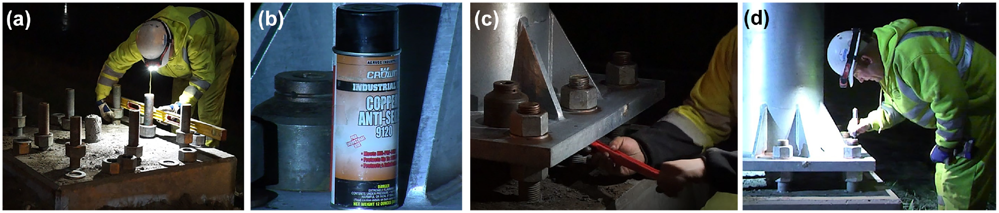
Installation procedures: (a) leveling nuts, (b) spray lubricant used, (c) snugging leveling nuts, and (d) marking for the turn of the nut.
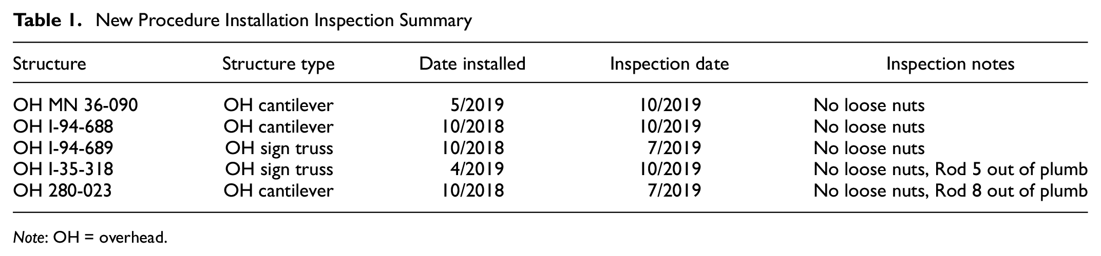
After the posts were installed, an inspection was performed to check for loose nuts. Table 1 shows information for each installation and inspection work. The time between installation and inspection ranged from 5 months to 2 years. During the inspection work, the nuts were checked with the typical procedure of striking washers with a hammer. Of the six structures, none had loose top nuts, and the only defects found were out-of-plumb anchor rods on two of the structures. OH I-35-318 and OH MN 36-090 were installed in early 2019 according to MnDOT. The results showed that the contractors were learning and implementing the new procedures well since they were installed without any guidance from the research team. On COSS OH 280-023, all of the nuts were tight, but after inspection of the leveling nuts, it was found that the middle nut was slightly angled with the rod itself out of plumb, likely causing the issue. When further investigated, it was discovered that the leveling of this particular installation took about 30 min, and the final installation was slightly out of plumb. The inspection results also indicated that Rod 5 on OH I-35-318 was slightly out of plumb but still adequately pretensioned. The successful installations indicated that the contractors were following the revised procedure fairly well; however, knowing the exact torques, lubricant, and tightening pattern used is not possible when inspecting the structure months or years after installation.
New Procedure Installation Inspection Summary
Note
In addition to verification of the previous installations, various contractors and stakeholders were interviewed for feedback on the Chen et al. procedures. Generally, all the feedback was to increase the clarity of the specification and simplify it. One of the common themes from all of the interviewed parties was to make a streamlined form for both verification and a reference chart ( 25 ). In the reference chart, it would likely be beneficial to order operations in sequence. The turns or torques could be included for each step instead of having the contractor go back and forth, trying to find half turns or half torques. Along with the changes to the chart, many of the MnDOT inspectors desired a broader verification form that could be utilized for several structures.
Inspectors from both structures and lighting construction indicated that implementing a rigorous installation inspection process for each individual structure would be burdensome and unlikely to be possible for every structure. To this degree, the inspectors wondered whether there was a suitable method for inspection after installation, so one could check a structure without being tied to a contractor’s schedule.
There were a few concerns with using turn of nut, especially in poles that have enclosed or transformer bases. For poles with high or transformer bases, the turn-of-nut method is unlikely to be possible on the top nuts since the bases do not allow enough room for full-size, manual-type wrenches. Furthermore, turning the leveling nuts on these same bases is not always practical, especially with light-pole bases when considering their overhang. In relation to the specifications, there were a couple of areas for improvement from the interviews. Overall, interviews confirmed suspicions from the literature review that the major source of anchor-rod pretension loss may be incorrect installation and a lack of verification.
Laboratory Test on a Signpost Structure
After field implementation and feedback from stakeholders were used to revise the Chen et al. procedures, it was important to verify that the revised procedures of using only torque-based tightening did not impact the connection performance. To achieve this, a full-scale lab specimen was installed using the revised procedures and subjected to LST-1 fatigue loading.
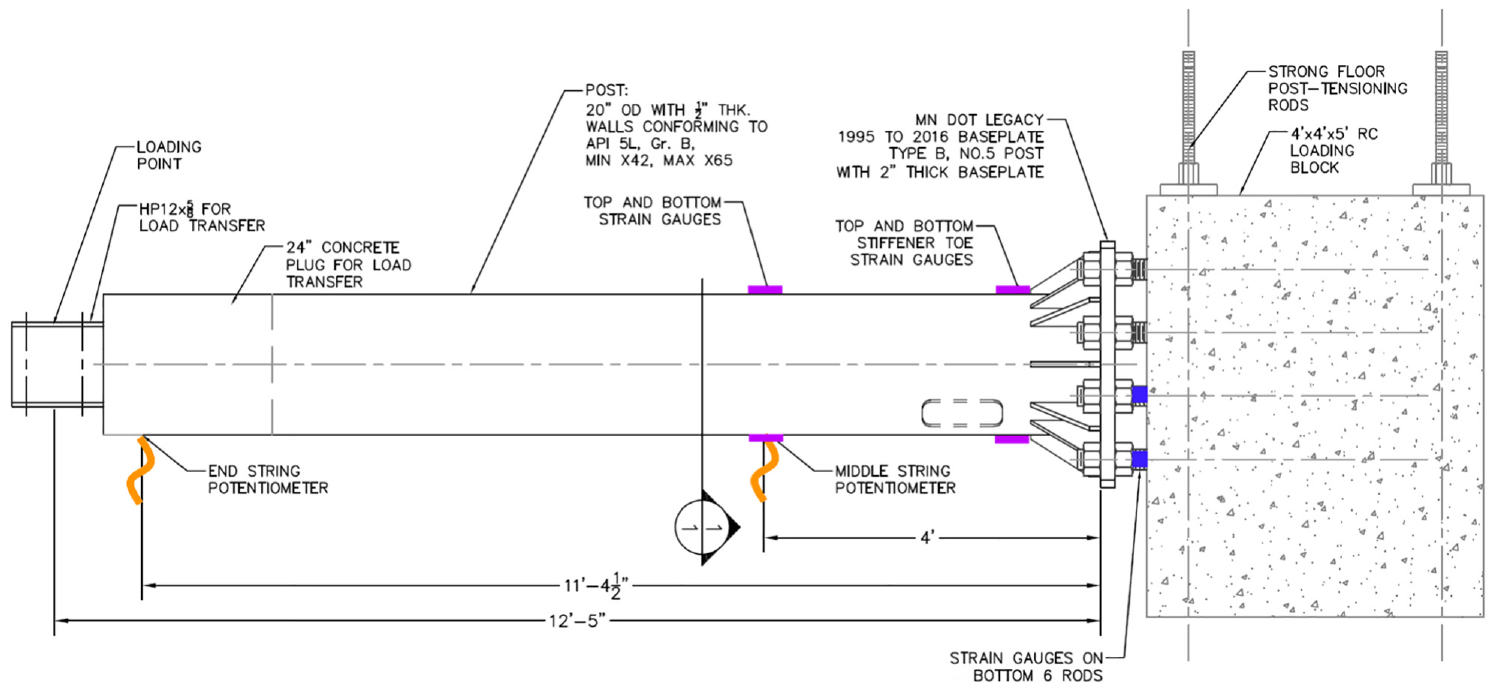
The signpost section was a legacy Type 5 design on a Type B baseplate ( 26 ). A legacy Type 5 post is Gr. 50 steel with a 20-in. outside diameter and bold-in. thickness. Owing to space constraints, a 12.5-ft long section of the post was tested. Figure 2 shows a general image of the experimental setup. Anchor rods were F1554 2bold-in. diameter, Grade 55. The anchor rods were cast into a reinforced concrete loading block during previous research activities. The loading block was posttensioned to the strong laboratory floor with 100 kips on each posttensioning rod to provide an approximate fixed condition. Loading was applied with an MTS Systems hydraulic actuator to an HP 12 × 74 steel section that was cast into the end of the post with a concrete plug. Figures 3 and 4 show the general instrumentation locations on the signpost laboratory structure.
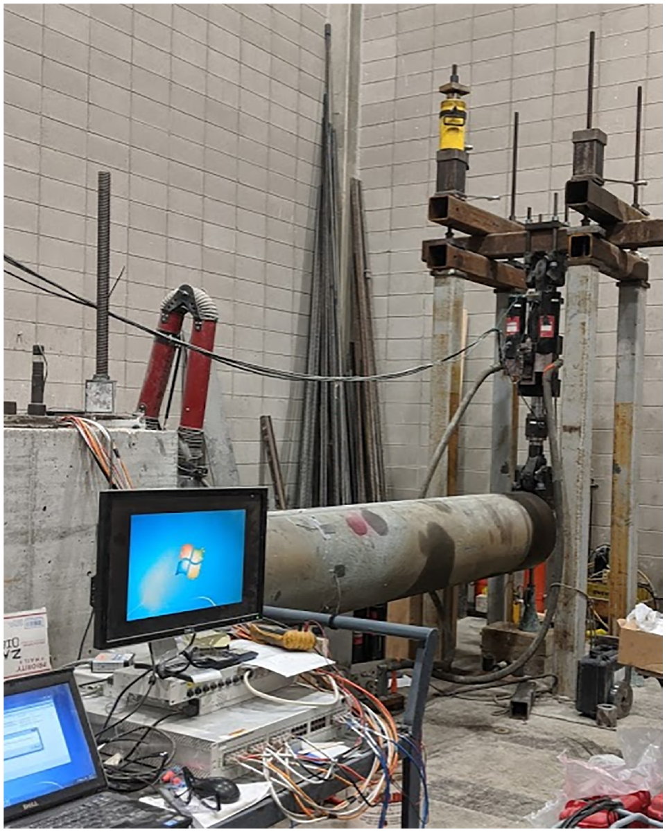
Test setup.
Base instrumentation.
Signpost instrumentation and test setup.
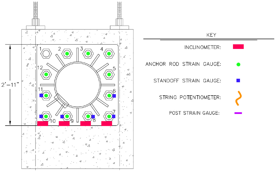
For further details on the loading block and signpost, see Chen et al. ( 24 ). Numbering for the anchor rods starts in the upper left corner and moves clockwise around the base. Strain measurements were acquired from three-wire, quarter-bridge resistance strain gauges from Tokyo Measuring Instruments Laboratory Co. On the post and standoff, 6 mm gauges were used. The anchor-rod strain gauges were BTM series gauges from the same manufacturer. They were drilled and epoxied into the anchor rods in the grip length, as covered by Chen et al. ( 24 ). Figure 5 shows the standoff strain gauges (located in the standoff distance of the anchor rods) and the top of the anchor-rod strain gauges. The standoff gauges were located on the side of the anchor rod to minimize strain readings from moment forces and measure primarily axial forces. Schaevitz AccuStar inclinometers were used to monitor any nut turns on the lower four nuts. The inclinometers were mounted on timber boards, as shown in Figure 5, to avoid damaging the instruments during attachment to the nuts. Inclinometers measure around the center of the instrument, which from geometry would be equivalent to any nut turns observed.
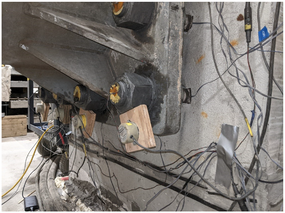
Lower signpost instrumentation.
For the fatigue test, anchor rods were pretensioned using the revised procedures. First, the pole was checked for level, and the top nuts were brought to hand-tight. Leveling nuts were then tightened with a strap wrench to approximately 50 ft-lb, given a large enough open-ended wrench was not available. Using a hydraulic wrench, the top nuts were tightened to 20%, 60%, and 100% increments of the verification torque, which is 3,300 ft-lb. A 48-h retightening torque was not applied to investigate the impact of relaxation on the rods without retightening.
Fatigue testing of the anchor rods was related back to a typical LTS-1 constant amplitude fatigue life (CAFL) of a known detail because the clamped grip lengths act composite with the sign structure, resulting in a lower induced stress than the anchor rods. Also, testing a known CAFL detail can give a reference benchmark for loosening to be related back to accepted standards since the stresses inside the anchor-rod grip length could vary if there is pretension loss.
The standoff anchor rods acted as the baseline LTS-1 CAFL. Using the equations and procedures from LTS-1, the post at the stiffener toe has a finite life constant, A, of 11 × 108 ksi 3 (kips per square inch) and a threshold, ΔF, of 7 ksi. The anchor rods have a threshold of 7 ksi. Both of the details are LTS-1 fatigue curve CAFL D ( 27 ).
From static testing, it was found that the standoff distances of the anchor rods could not be brought to their full threshold stress, or CAFL, owing to concerns about prematurely failing the post, as with James et al.’s ( 2 ) research. The middle lower rod standoffs (for Rods 8 and 9) were the controlling anchor-rod stresses. The lower two anchor-rod standoff distances were stressed to an average of 166 Δμϵ (4.8 ksi), which aimed for LTS-1 fatigue curve CAFL E. Standoff strains corresponded to 1,088 Δμϵ (31.6 ksi) at the weld toes of the structure and 51 Δμϵ (1.5 ksi) in the anchor-rod grip lengths of Rods 8 and 9.
Equation 11.9.3-2 from LTS-1 ( 28 ) was then used to find the theoretical cycles to failure for the post in a finite life, since the 32-ksi stress reversal is greater than the CAFL for the details of 7 ksi. However, before determining the cycles, laboratory-measured strains needed to be corrected for stress concentration factors since they were measured near a weld toe. An LTS-1 fatigue stress concentration factor, Kf, from Table 11.9.3.1-1 from LTS-1 ( 28 ), for the detail, was calculated at 2.28, giving 20 ksi as the stress to use for calculating the number of test cycles.
Using the LTS-1 calculation procedure, the finite lifespan of the signpost was found to be 137,500 cycles at 20 ksi stress reversals at the top and bottom stiffener toes. After derivation, the sample was tested at a frequency of 1 Hz. A major crack or failure was not discovered after 800,000 cycles of the loading outlined above, or about six times the AASHTO design life.
Given that no cracks were discovered, it was decided to load the standoff strains to their full LTS-1 CAFL of 7 ksi. In this fatigue test, the critical anchor-rod standoffs were strained at 250 Δμϵ (7.25 ksi), which corresponds to signpost-stiffener toe strains of 1,500 Δμϵ (43.5 ksi) and anchor-rod grip-length strains of 75 Δμϵ (2.2 ksi).
The loading was applied using the MTS actuator in a sinusoidal pattern with an amplitude of 11.5 kips at 1 Hz. This test ran for 9,450 cycles before failing the top cross-beam of the testing frame in fatigue. It is likely that the fatigue crack in the frame had been initiated during the previous fatigue test and was brought to failure by the higher number of loading cycles.
Overall, the final cycles brought the total LTS-1 design life to 6.2 times longer than allowed in the signpost detail specifications. To check for microcracking, dye penetrant testing was utilized, but observations were inconclusive owing to the rough surface on the post and possible crack locations being longitudinal to welds, which made proper cleaning difficult. A summary of the final fatigue test pretension losses is presented in Table 2. The strains after initial pretension, 48-h relaxation, fatigue testing, and immediate loosening (when the nut was removed after testing) are illustrated for a full overview of the strain losses in the signpost. The absolute pretension losses in the anchor rods were recorded during nut removal to validate the losses recorded at the end of fatigue testing.
AASHTO Reference Detail Replicated Fatigue Pretension Loss Results3
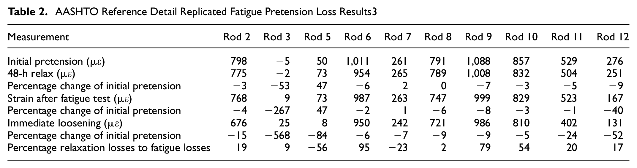
The results in Table 2 show that there is a fair amount of variability in the individual rod results, probably owing to the differential sensitivity of the embedded anchor-bolt strain gauges. Because of the strain variability, each anchor rod’s performance was compared relative to itself in relation to percentage losses. In addition, Rods 3 and 5 were not considered owing to sensitivity issues, and the gauge for Rods 1 and 4 was not operational during the test. After the 48-h relaxation, the average loss from the initial prestrain was −3.9%. Note that the 48-h losses were recorded after tightening, so the “initial prestrain” does not account for the immediate, approximately 30-min losses.
After the fatigue test, the average overall loss, including the relaxation, was −7.9% for the anchor rods, with Rod 12 having the greatest overall loss of −40% of the initial strain. When directly loosened, the total average losses amounted to −16.1% of the initial prestrain. The immediate loosening value was taken to be more reliable than the final fatigue value because the absolute strain loss could be immediately measured practically without temperature and strain drift impacts. Taking the immediate loosening values was also more conservative, as the average recorded losses were approximately double those recorded at the end of the fatigue test. All inclinometers indicated negligible turns after the fatigue test, with a maximum change of 0.025° (1/14,500 of a turn), which is within the error range for the inclinometers. These minimal turns indicated that transverse loading is likely not a primary loosening mechanism, which matched expectations from the literature ( 11 ). Considering the immediate loosening, an average of 14% of all losses came from losses recorded 48 h after the initial pretensioning.
It is likely that fatigue loading does not have a significant impact on connection loosening if the anchor rods are properly pretensioned. There was an average total pretension loss of 16% on details that were tested to six times their specified fatigue life. Of those losses, 86% occurred in the first 48 h before commencing fatigue loading in the anchor rods, which suggests that initial relaxation is more of a contributing factor than fatigue loading for properly installed connections. The results also indicated that loose connections are more likely to be the result of improper installation than flawed methodology. Therefore, it is critical that procedures are straightforward to install.
Conclusions and Recommendations
Based on the results from field deployment, the Chen et al. tightening procedures worked effectively on resisting anchor-rod loosening ( 24 ). Feedback from stakeholders and observations during construction led to revised procedures. Finally, the laboratory test indicated that the revised procedures and pretension level effectively resisted fatigue loosening. Overall, the final changes to the procedures focus on force-controlled torque installation for greater applicability and accuracy in the wide variety of MnDOT SLTS structures.
Verify Lubrication Areas
With both overhead sign and light pole installations, contractors expressed uncertainty concerning the exact areas to lubricate besides the anchor rods. Proper lubrication on all faying surfaces is critical for proper installation. Contractors often needed specific instructions on which areas needed to be lubricated on the nuts and washers.
Specify Steps in Logical Manner
Each required step should probably be laid out as an individual torque so steps can be logically followed one at a time without having to go back and forth with half torques. Additionally, it may be beneficial to add some descriptions to the steps to explain why they are important to follow for contractors.
Lubrication
Throughout implementation, the specified MnDOT bridge grease was generally not used on installations. However, the majority of lubricants were a sort of antiseize compound. A review of various literature suggested that the nut factors of many of the used greases are comparable to the specified grease, but verification for specific cases was required.
Specification Simplification
Fewer steps could probably be used than are currently specified. In all of the maintenance and most of the installations, steps were skipped when bringing nuts to snug-tight and with the verification torque. The reasoning for the steps is to prevent differential stresses in the rods; however, doing two steps at snug and two steps at verification may not be sufficiently proportional to cause major differentials in rod stresses compared with taking bolts from snug to fully tightened. Contractors and maintenance workers also expressed that there could be confusion over the “snug-tight” term, as many field personnel misunderstood it to mean hand-tight or an approximation. Changing the specification to four torque steps of 20%, 60%, 100%, and 100% (repeated) is recommended. Additionally, a minimum 10-min relaxation period in between the repeated 100% torques would be ideal, although the precise timing could be researched in more depth to determine a more accurate retightening timeframe.
Footnotes
Author Contributions
The authors confirm their contribution to the paper as follows: study conception and design: B. M. Phares; data collection: Z. Dietrich, Z. Liu; analysis and interpretation of results: Z. Dietrich, Z. Liu; draft manuscript preparation: Z. Dietrich, Z. Liu, B. M. Phares. All authors reviewed the results and approved the final version of the manuscript.
Declaration of Conflicting Interests
The authors declared no potential conflicts of interest with respect to the research, authorship, and/or publication of this article.
Funding
The authors received no financial support for the research, authorship, and/or publication of this article.
Data Accessibility Statement
All data, models, and code generated or used during the study appear in the submitted article.