
Abstract
The cutter wear of a shield machine is severe in highly abrasive strata. The inspection and replacement of cutters takes up a high proportion of time during construction. It is necessary to investigate the rule of cutter wear and the influence of various related factors on cutter wear. Based on the cutter wear data of the Guangfo East Ring Tunnel in China, the characteristics of cutter wear are analyzed. Abnormal wear failure accounts for 23.28% of the total number of cutter changes. The influence of factors such as total thrust of the shield machine, cutter head torque, soil chamber pressure, cutter penetration, uniaxial compressive strength of strata, and earth pressure on cutter life are explored. There is a significant negative correlation between the cutter life and uniaxial compressive strength or thrust of rock strata. Parameters that have a negative correlation with the cutter life include total thrust of the shield machine, cutter head torque, and uniaxial compressive strength of the rock strata. Based on the theory of the response surface model, a cutter life prediction model under the siltstone condition is established. The uniform wear prediction model of the front disc cutter is established and proved.
Keywords
The tunnel boring machine is widely used in rail transit construction because of its high boring efficiency and construction safety performance ( 1 – 3 ). The shield machine cuts and crushes broken rock and soil using the cutter head, creating a space for advancement. During shield tunneling, severe cutter wear reduces the tunneling efficiency ( 4 ). In highly abrasive rock strata, the cutters used for rock-breaking are severely worn ( 5 , 6 ). There are more dangers and issues in the inspection and replacement of cutters in an unstable tunnel ( 7 , 8 ). The inspection and replacement time of cutters accounts for 20%–40% of construction time ( 9 ). To reduce cutter wear and correctly select the cutter change position, it is particularly important to investigate the influencing factors of cutter wear and establish a suitable cutter wear prediction model.
Disc cutters are suitable for breaking hard rock because of their strong rock-breaking ability. The rock surface is crushed under the action of the vertical thrust of the disc cutter and the advancing force parallel to the rock surface. Shear and tension failure occur in the rock because of the action of tine blocks ( 10 , 11 ). As shown in Figure 1, there are radial cracks on the rock, which develop and extend to cause rock fracture ( 12 ). Hard abrasive particles in the rock and soil grind the surface of the cutting edge during the process of cutter crushing. The surface of the disc cutter deforms and attrites, resulting in abrasive wear. Some hard particles are pressed vertically into the surface of the cutter edge, causing plastic deformation, and forming adhesion points. The adhesive point is sheared under tangential load and adheres to the surface of the falling hard particles to cause adhesive wear. The main causes of disc cutter wear are abrasive and adhesive wear. Secondary causes are fatigue wear caused by alternating contact stress of the cutter in contact with rock and soil, and oxidation wear.
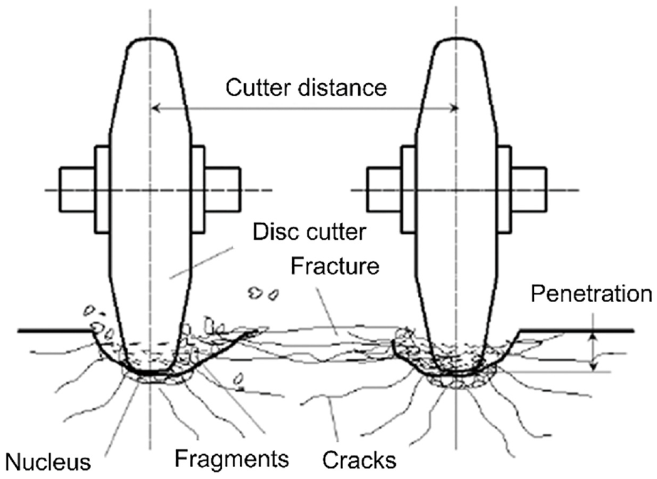
Schematic of disc cutter breaking rock.
Disc cutter wear is affected by many factors, such as geology, construction process, and the material properties of the cutter ( 13 , 14 ). The main wear mechanism and generally accepted influencing factors are machine equipment, geological parameters, and construction management, as in Figure 2. Disc cutter wear failure types are mainly divided into abnormal and uniform wear failure. Uniform wear failure accounts for the largest proportion ( 15 ). Abnormal wear failures include partial wear, dropped gaskets, rolled edges, and damaged or cracked cutter rings ( 16 ).
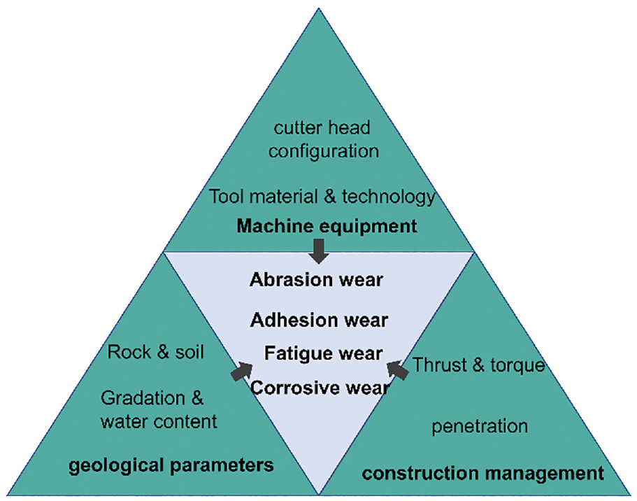
Cutter wear mechanism and influencing factors.
The existing disc cutter prediction models are mainly divided into two categories: 1) an empirical prediction model based on existing measured wear data and 2) a semi-theoretical wear prediction model considering the force and wear mechanism of the disc cutter ( 17 – 20 ). For example, Hassanpour proposed a relationship between cutter life and geological parameters based on statistical analysis and an empirical equation ( 21 ). Yang analyzed the failure and consumption of a disc cutter on a water conveyance tunnel section based on data from a Lanzhou construction project ( 22 ). Pourhashemi performed statistical analyses on collected and screened data (41 data sets), and developed some simple, site-specific, empirical equations to predict the cutter performance on grinding mode ( 23 ). The accuracy of the empirical prediction model is limited to specific strata. Previous research focused on the nature of the rock and cutters, while the dynamic changes of parameters in the process of shield tunneling were not comprehensively studied. Most of the wear prediction models focus on uniform wear. The number of abnormal wear failure disc cutters and the negative effects cannot be ignored. The influence degree and mechanism of each tool wear factor need to be further investigated.
In this paper, based on the disc cutter wear field data of Guangfo East Ring Rail Transit tunnel in China, the cutter wear rules and characteristics during the construction process are explored. The relationship between machine performance parameters and cutter service life is discussed. Thereafter, a prediction model considering uniform wear and abnormal wear of the disc cutter life is established and the uniform wear prediction model of the front disc cutter is established and proved. The above two prediction models can be combined to determine the position and frequency of opening the chamber and changing the tools.
Project and Shield Machine Overview
Project Overview
The Guangzhou-Foshan Circle Line of the Pearl River Delta Intercity Rail Transit has a total length of 46.537 km and consists of 10 stations. As part of the Guangzhou-Foshan East Ring Tunnel, the total length of the line from the Dayuan station to the Taihe station is 6,804 m, as shown in Figure 3. Two earth pressure balance (EPB) and tunnel boring machine (TBM) dual-mode shield machines are applied for tunneling construction.
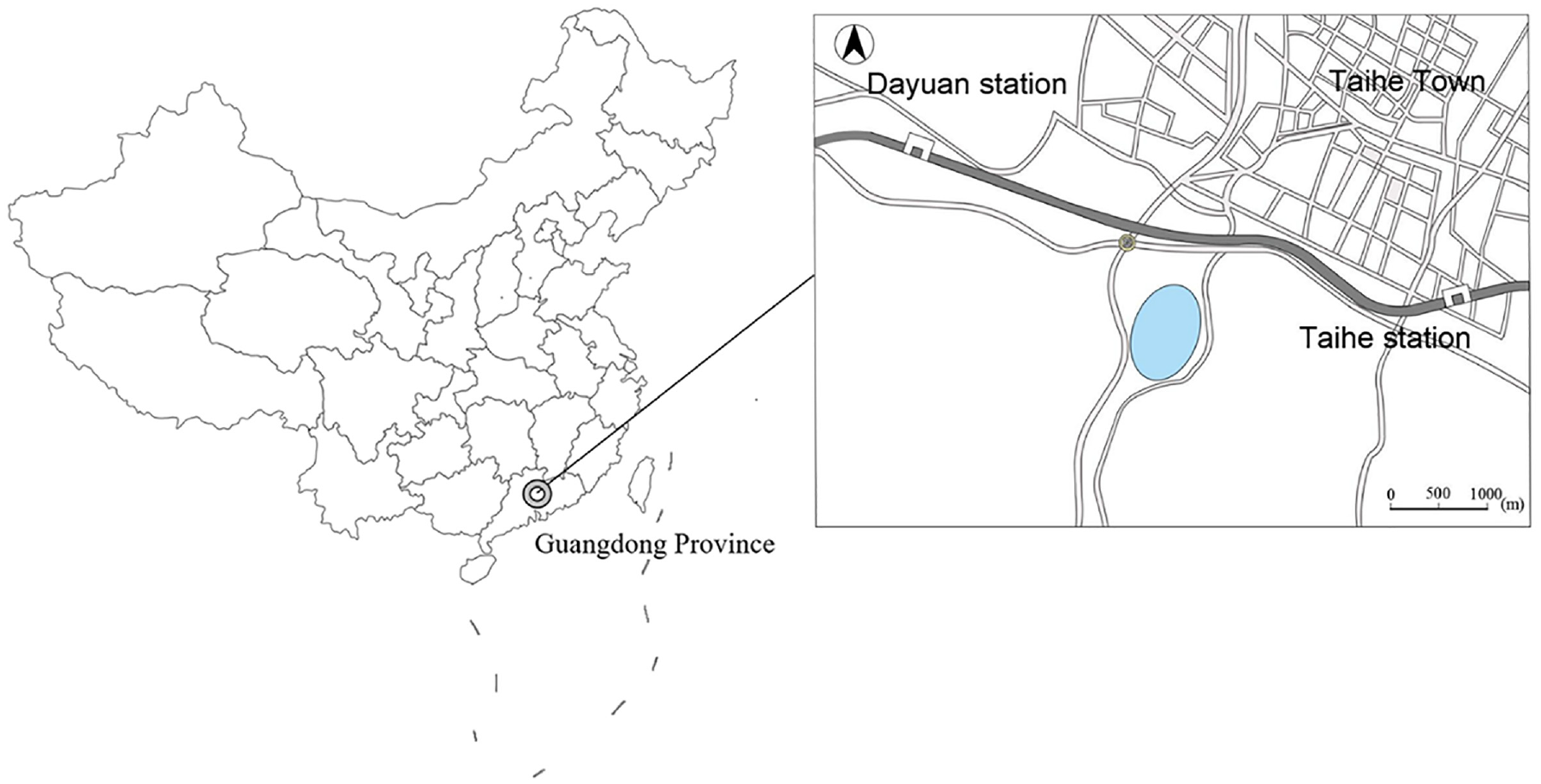
The tunneling route of Dayuan station to Taihe station.
Project Geological Conditions
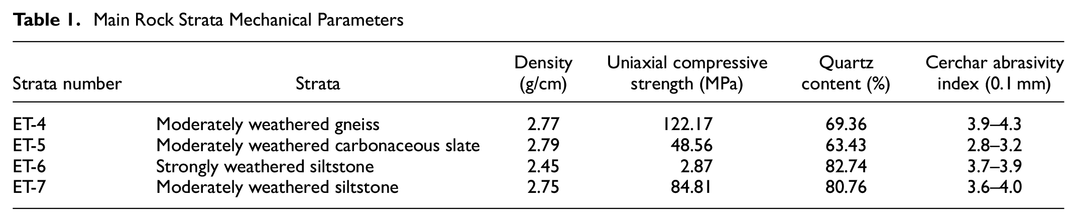
The Guangfo project tunnel mainly passes through two strata: siltstone and gneiss. The siltstone has loose structure, fine particle cementation, main silt, and a small amount of argillaceous. Siltstone’s main component is quartz, with a small amount of feldspar, and the color is red-brown. The gneiss is a rock formed by deep metamorphism of magmatic rocks or sedimentary rocks. It has the gneissic structure characteristics of directional or banded discontinuous arrangement between dark and light minerals, and it is a crystalline structure. In the designed route, 97 boreholes were extracted, and it was learned that the strata that the tunnel mainly passes through are moderately weathered gneiss (32%) and strongly weathered siltstone (25%). The depth and location of partial borehole samples is shown Figure 4. The proportion of each stratum is shown in Figure 5. The uniaxial compressive strength of the rock sample is 2.87 to 122.17 MPa. The region with low uniaxial compressive strength ranges from chainage 39 + 500 m to chainage 42 + 500 m, mainly passing through moderately weathered and strongly weathered siltstone formations, with compressive strength ranging from 2.87 MPa to 84.81 MPa (mean average value 67.59 MPa) (number of samples tests is 24), while the region with high uniaxial compressive strength ranges from chainage 36 + 000 m to chainage 39 + 500 m, mainly passing through moderately weathered gneiss and moderately weathered carbonaceous slate, with compressive strength ranging from 48.56 MPa to 122.17 MPa (mean average value 98.60 MPa) (number of samples tests is 37). The quartz content of highly abrasive strata is 63.43% to 82.74%. The cutter wears heavily during tunneling in the high-quartz-content strata. Frequent changes of rock compressive strength and the uneven soft and hard rock layers bring difficulties to tunneling work. The tunnel site is situated in a hilly landform with large elevation changes, and the tunnel cover is 14.5 to 158 m. The mechanical parameters of strata are shown in Table 1. The tunneling strata profile is shown in Figure 6.
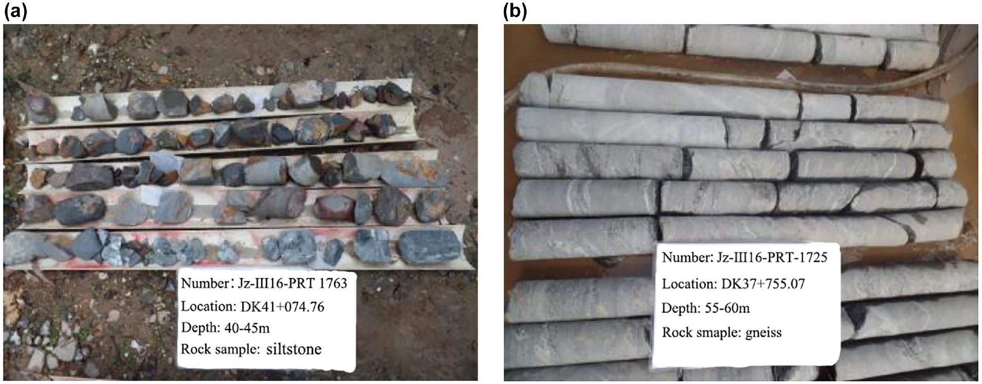
Depth and location of partial borehole samples: (a) siltstone sample, (b) gneiss sample.
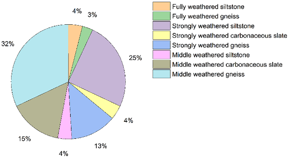
Strata proportion.
Main Rock Strata Mechanical Parameters
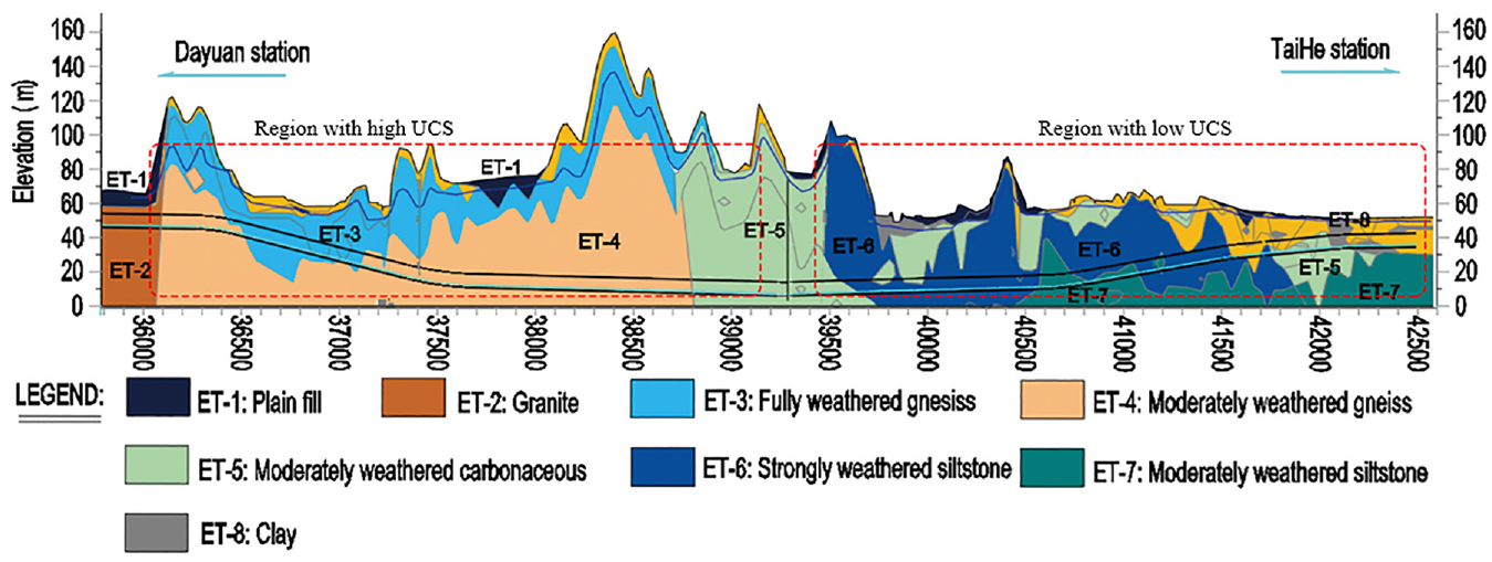
Schematic of the longitudinal section of the tunneling strata.
Shield Machine and Cutter Head
Two EPB and TBM dual-mode shield machines are used to tunnel in the west and east lines simultaneously. The two TBM had the same cutter head configuration and there are no differences between the two. This kind of shield machine has been developed and used in China in recent years, combining the advantages of the TBM and EPB shield machines.
The dual-mode shield machine changes the slag discharge method by replacing the belt conveyor and the screw conveyor at the back of the cutter head. The EPB mode is used in sections with weak and unstable surrounding rock or sections that have high requirements for settlement safety, while the TBM mode is used in sections with full section hard rock and high abrasion rock. The main parameters of the shield machine are listed in Table 2.
Shield Parameters
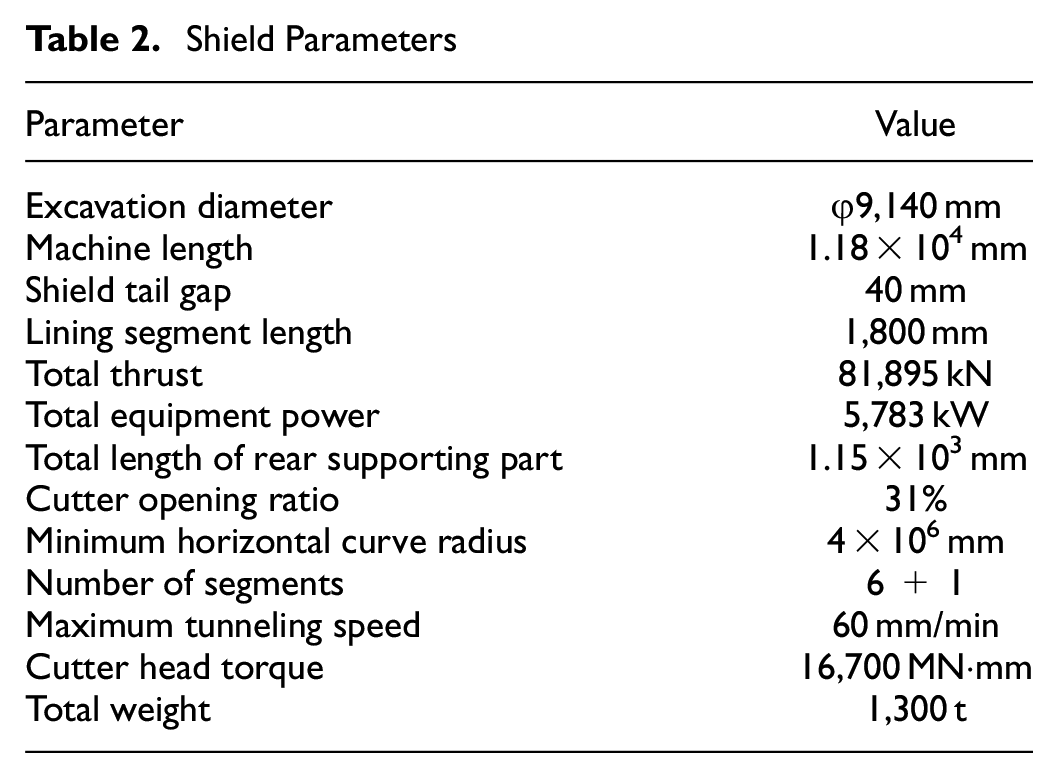
The cutter head is composed of one-plus-two composite blocks. There are six 17 in. double-blade center disc cutters, thirty-six 19 in. front disc cutters, eleven 19 in. edge disc cutters, 114 cutters, and 16 pairs of scrapers in the cutter head; all hob materials are mainly hot work die steel. As shown in Figure 7, the center cutters are S 1–12 cutters, the front cutters are S 13–48 cutters, and the edge cutters are S 49–58B cutters. The disc cutter structure is shown in Figure 8.
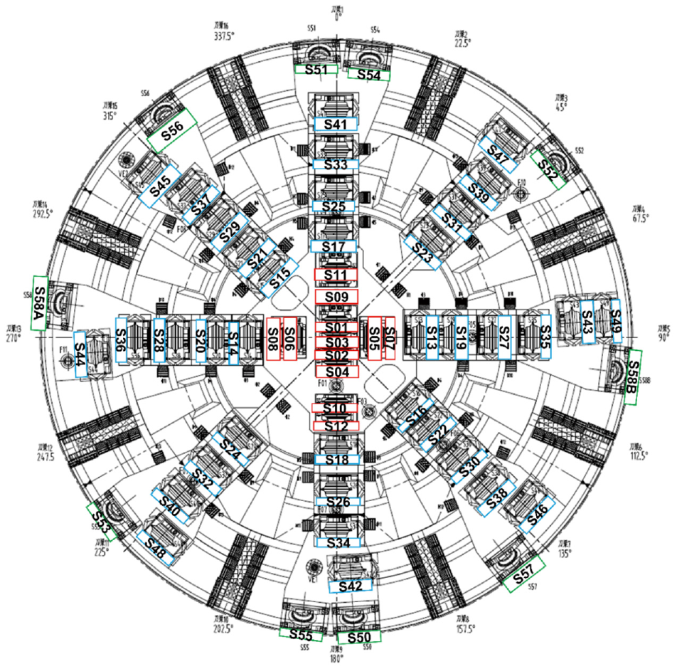
Shield machine cutter head.
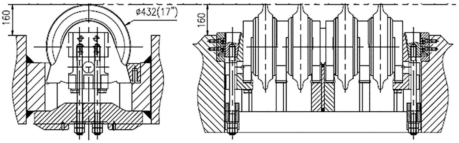
Disc cutter structure layout.
Cutter Wear Characteristics
To investigate the wear rule and failure types of disc cutters under highly abrasive strata, the disc cutter wear field data of ring numbers 1 to 450 are collected. The main types of strata crossing are moderately weathered and strongly weathered siltstone, which have high abrasion, weathering crack development, and large block masonry structures. It is found that the cutter wear is divided into abnormal and uniform wear failure. The photos of the cutter wear are shown in Figure 9. The abnormal wear failure rate of the disc cutter accounted for 23.28% of the total number of cutters replaced and, additionally, partial wear which belongs to abnormal wear accounted for 14.2% of total replaced number. The reason may be that from chainage 41 + 675 m to 41 + 484.6 m, the stratum is mainly composite, comprised of siltstone of various weathering degrees. Uneven rock strata will increase cutter wear and reduce cutter stability and the probability of the disc cutter breaking is increased ( 24 ). A part of the completely weathered siltstone cannot provide enough starting torque for the disc cutter, resulting in serious eccentric wear.
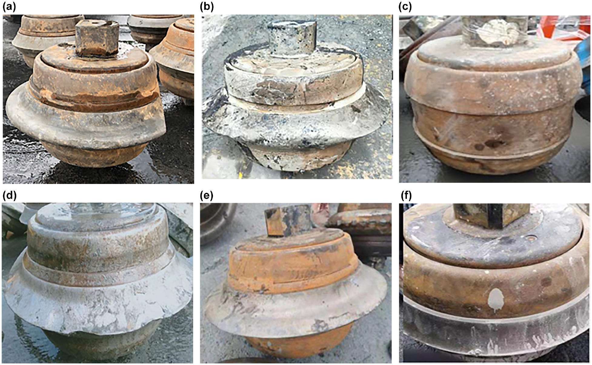
Cutter wear scene photos: (a) partial wear, (b) dropped shield ring, (c) falling or broken cutter ring, (d) curling blade, (e) sharpened blade, and (f) uniform wear.
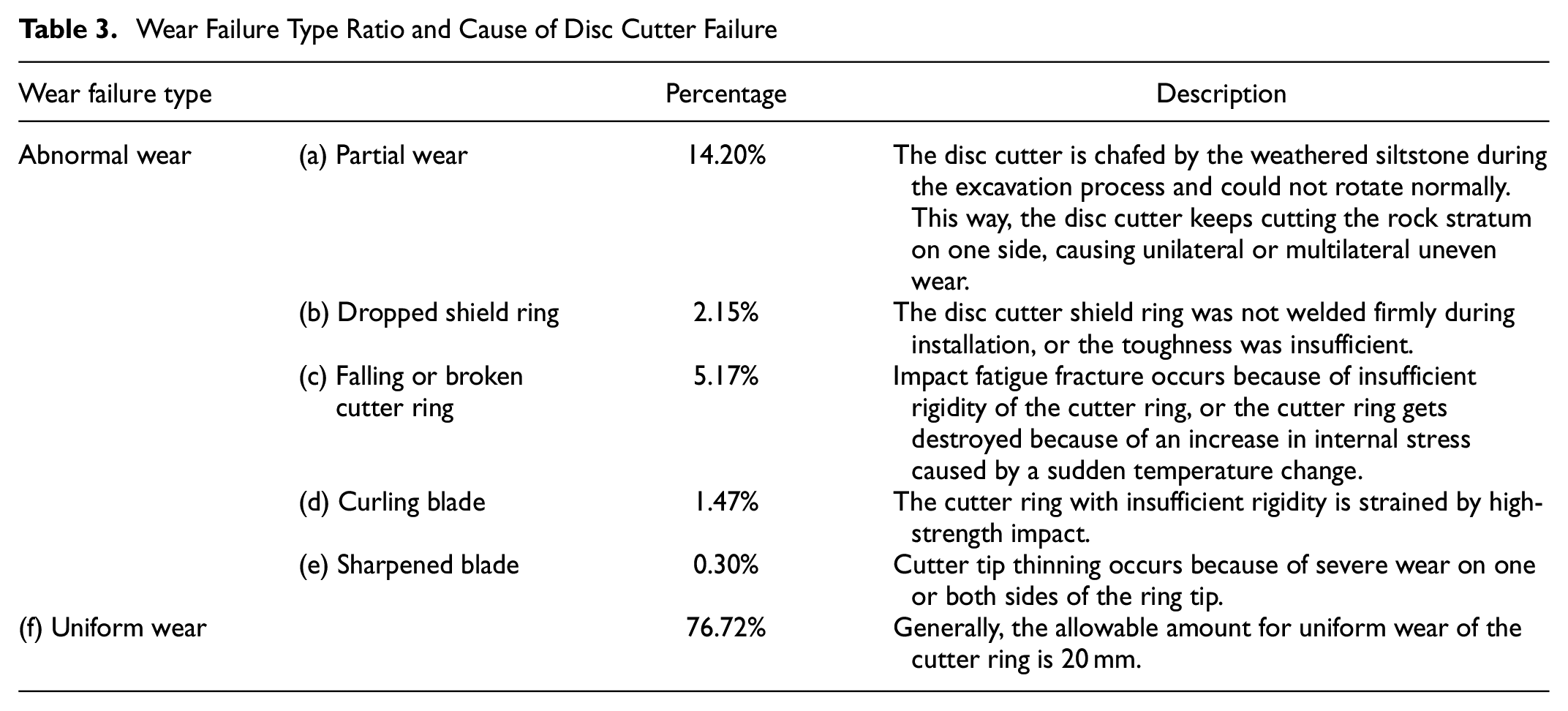
In the process of west and east line tunneling, 315 disc cutters were replaced, including 292 single-edged disc cutters and 23 double-edged disc cutters. The type and proportion of cutter wear failure during shield tunneling are shown in Table 3.
Wear Failure Type Ratio and Cause of Disc Cutter Failure
Cutter wear is measured and summarized in the west and east lines, and the result is called the “cumulative wear.” The cumulative statistics of uniform wear during shield tunneling is shown in Figure 10 and Figure 11. According to the distance of different cutters from the center, the cutter head is divided into three areas namely the central area, frontal area, and edge area. The dotted line and the value above it represent the average value of tool wear in the area. Taking the west-line data as an example, the distribution of the disc cutter wear shows the following characteristics:
The cumulative average wear of the cutters in the central area (S 1–S 12) is the least among the three areas. The maximum value is 87 mm, the minimum value is 3 mm, and the average value is 31.58 mm. The uniform wear of the cutter increases with the increase in cutter radius.
The cumulative average wear of the cutters in the frontal area (S 13–S 48) is two to three times that of the cutters in the central area. The maximum value is 129 mm, the minimum value is 7.4 mm, and the average value is 67.81 mm. The cutter wear gradually increases with the increase in the center distance, and the most severely worn position is that of the outer ring in the frontal area.
The cumulative average wear of the cutters in the edge area (S 49–S 58B) is the largest of the three areas, that is four times the wear of the cutters in the central area. The maximum value is 196.2 mm, the minimum value is 76.5 mm, and the average value is 138 mm. Cutter wear is the most severe in the edge area. Affected by the change in the deflection angle of the installation of the edge cutter, the wear of S 58A and S 58B cutters decreases with the increase in the number of the cutters.
Overall, the uniform wear of the cutters increases with distance. The reason is that the distance of the cutter chip breaking rock increases with increasing center distance. The cutter pitch is an important factor affecting the cutting efficiency of the cutters ( 25 ). The cutter pitch in the central area is 203 mm, and in the frontal area is 624 mm. AUTODYN was applied to simulate the rock-breaking process of cutter chips at different cutter pitches and penetrations, and the author obtained the highest rock-breaking efficiency when the ratio of pitch-to-penetration is 10–12 based on the principle of minimum specific energy ( 26 ). The average penetration of the disc cutter is 23 mm, and the suitable cutter pitch is 230–460 mm. The center disc cutter pitch is reasonable, leading to less tool wear. A reasonable design of the cutter pitch is conducive to the workload of rock-breaking and reduces cutter wear. The specific energy of the double-edged disc cutter is lower than that of the single-edged disc cutter ( 27 ). The rock-breaking efficiency of the double-edged disc cutter is higher, which is also the reason for less cutter wear in the central area.
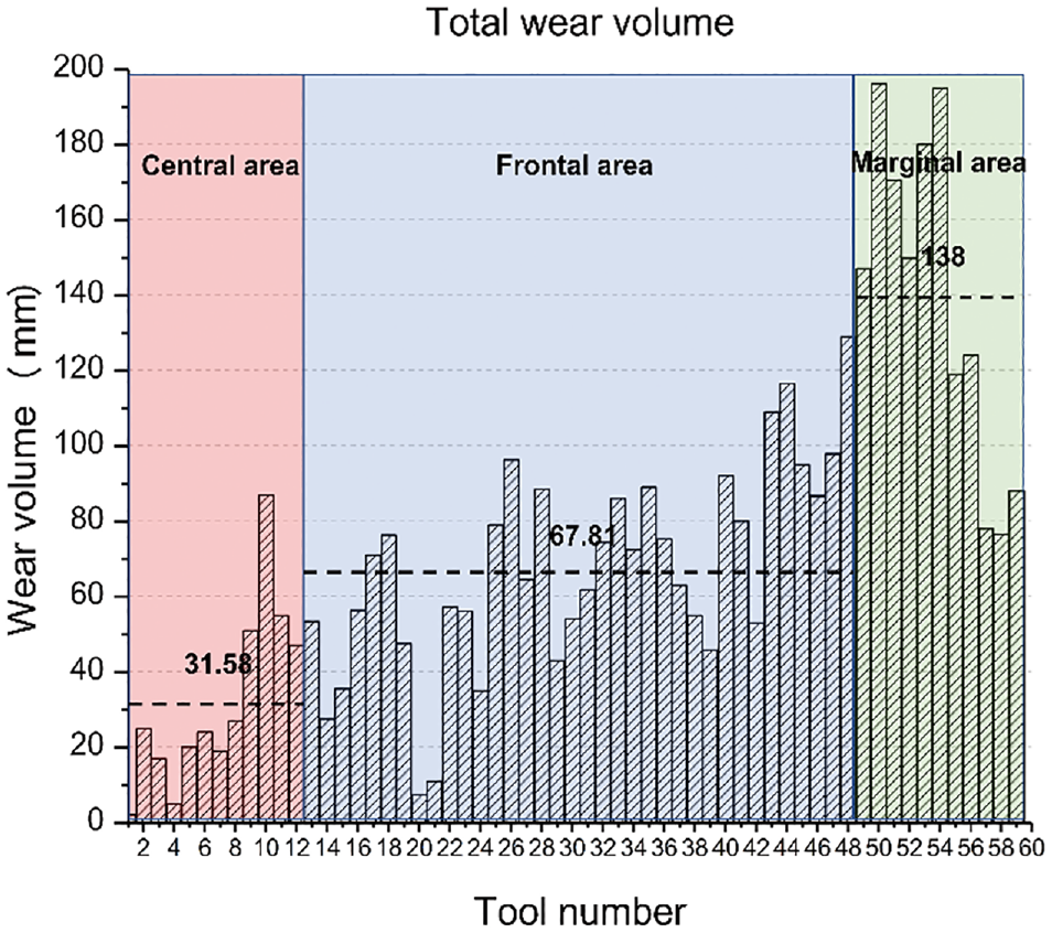
Total uniform wear of the west-line tool.
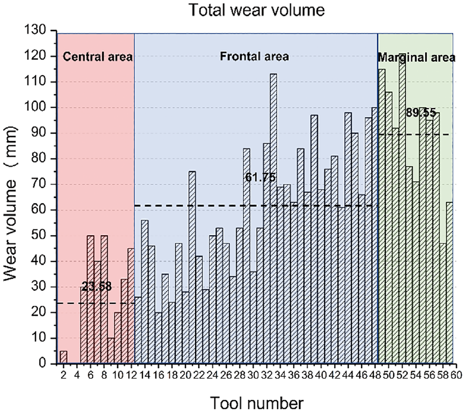
Total uniform wear of the east-line tool.
The statistics of abnormal wear failure of the three cutter areas during west and east line tunneling are shown in Figure 12. The abnormal wear failure in the frontal area is more serious, accounting for 17.18% of the total tool changes. The main reason is that the frontal area and the central area undertake the main function of cutting and breaking the rock and discharging slag. The frontal area is large, and the maximum tool pitch is 624 mm, which is three times that of the central area. Compared with the central area, it is more difficult for the fracture in the adjacent middle region to penetrate. When the rock is broken, the cutter is more stressed, resulting in an increased frequency of abnormal wear failure.
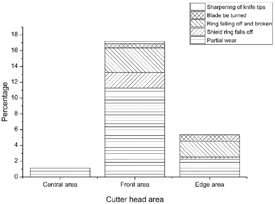
Percentage of abnormal failures in the three cutter head areas of the total cutter change data.
Factors Influencing Cutter Wear
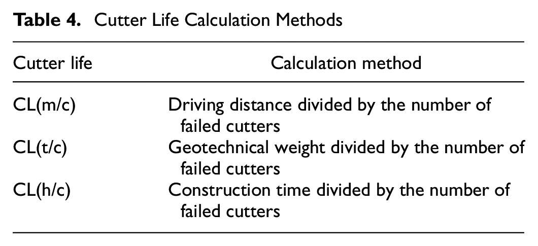
“Cutter life” is defined as the amount of time that each of the cutters is used until it was replaced. Based on the west-line cutter change data, the cutter life is calculated through three different methods, as shown in Table 4 and Figure 13. Cutter life is calculated by three different methods: CL(m/c) is calculated by dividing the driving distance by the number of failed cutters—this means the driving distance of each replacement cutter heading forward; CL(t/c) is calculated by dividing the geotechnical weight by the number of failed cutters—this means the weight of soil excavated by each cutter consumed; and CL(h/c) is calculated by dividing construction time by the number of failed cutters—this means the average working time before failure of each cutter. The change trend of the cutter life presented by the three calculation methods is similar, which provides an explicit comparison for studying the influence and correlation of various relevant factors on tool wear from a macro perspective.
Cutter Life Calculation Methods
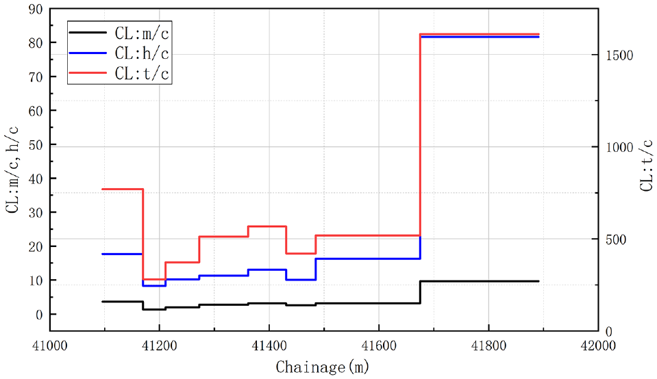
Statistical results of three west-line cutter life conversion methods.
The shield machine applies a thrust force to the segment through a hydraulic driving device, so the reaction force generated pushes the front shield forward. The cutter head rotates while advancing, and the torque is provided by the driving device. Higher thrust and torque indicate stiffer ground and under-conditioned soil. The stability of the excavation surface is achieved by maintaining earth pressure. The earth pressure is proportional to the stability of the excavation strata. The penetration of the cutter is determined by the advancing speed and the speed of the cutter head. The penetration of the cutter indicates the depth of the rock sample cut by the cutter.
The relationship between thrust, torque, and cutter life is shown in Figure 14. The service life of the cutter has a significant negative correlation with the thrust and torque of the shield tunneling. In the tunneling section, when the thrust and torque values are both above average, the cutter life is lower, otherwise it is higher. In the chainage of 41 + 675 m to 41 + 891 m, as the thrust and torque decrease significantly, the cutter life increases. Affected by changes in the stratum conditions, the trend of the thrust and cutter head torque is the same in the chainage of 41 + 095 m to 41 + 272 m and 41 + 380 m to 41 + 891 m.
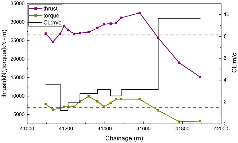
Statistics of the cutter head total thrust, torque, and cutter life.
The interaction force between the cutter and the rock stratum is affected by the thrust and torque of the shield. This force increases with the increase of the thrust and torque. The tribological study of abrasive wear shows that the vertical stress on the contact surfaces of the two particles has a positive correlation with the severity of abrasive wear. The main wear of the hob is caused by abrasive wear, so the cutter life has a negative correlation with both thrust and torque. The thrust and torque of the shield in the chainage of 41 + 484 m to 41 + 678 m are the highest, and the thrust reaches 32,507 kN. Statistically, the abnormal wear of the cutter in this section is severe. A total of 53 disc cutters were replaced, of which 23 disc cutters were unevenly worn in varying degrees, and seven disc cutters were both unevenly worn and their retaining ring dropped. If the thrust is too large, the impact force of the rock sample on the cutter is too large, which may cause the retaining ring to be unstable or even fall off, changing the normal rotation trajectory of the disc cutters and increasing the phenomenon of partial wear.
The relationship between cutter penetration and cutter life is shown in Figure 15, showing a positive correlation between the changes in the chainage of 41 + 095 m to 41 + 510 m. However, the cutter life increases with the apparent decrease in penetration, showing a negative correlation in the chainage of 41 + 510 m to 41 + 891 m. It is found that the relationship between tool penetration and cutter life is not a single positive or negative correlation. This is different from the assumption that the increased cutter penetration will reduce the number of cutter changes during the tunneling process according to a prediction model. Increasing the penetration properly can increase the rock breaking efficiency, but a very large or small penetration can cause serious cutter wear.
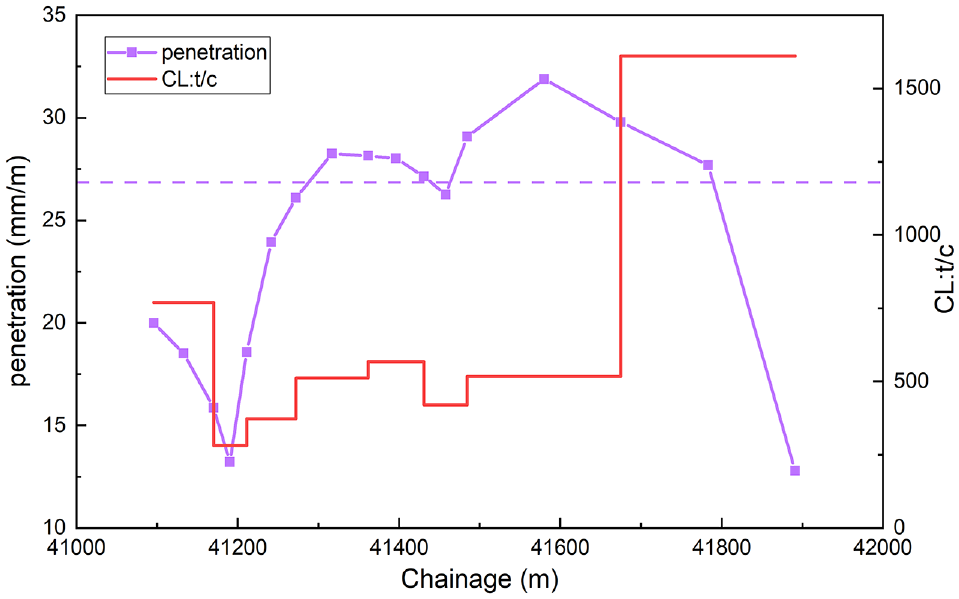
Statistics of penetration and cutter life.
The disc cutter directly acts on the rock stratum for cutting and the hard debris wears the cutting surface of the cutter directly, leading to a direct relationship between the mechanical properties of the rock stratum and cutting tool wear. Studies have found a clear positive correlation between rock compressive strength and cutter wear, with a weak positive correlation between the rock shear strength and cutter wear ( 28 ). It was also found that excessive cutter wear was caused by high quartz content and hard matrix sandstone, and the tool was quickly dulled in abrasive rock ( 29 ).
Statistics of rock stratum uniaxial compressive strength, soil chamber pressure, and cutter life are shown in Figure 16. In the chainage of 41 + 095 m to 41 + 272 m in which the rock stratum is mostly weathered siltstone, the natural compressive strength is above 37 MPa and the cutter life is low. In the chainage of 41 + 580 m to 41 + 891 m where the rock stratum is mostly strongly weathered siltstone, natural compressive strength of the stratum shows a downward trend. Cutter wear in this range is reduced and cutter life is increased. Therefore, there is a negative correlation between cutter life and compressive strength of rock strata. Through regression analysis, it is found that the correlation coefficient between the uniaxial compressive strength and cutter life is 0.8117. Higher stratum compressive strength requires more cutter thrust to penetrate and cut. Tunneling parameters are also affected by rock stratum parameters, while the cutter life is affected by both tunneling parameters and rock stratum parameters simultaneously.
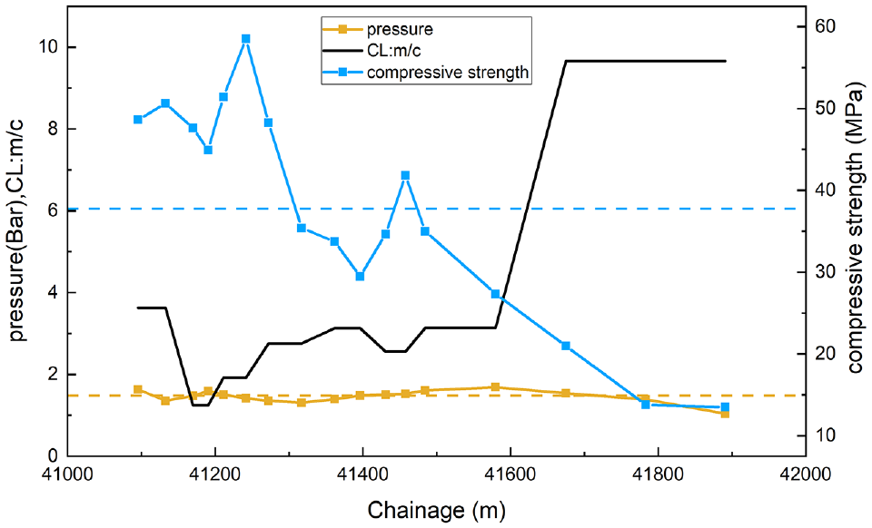
Statistics of stratum uniaxial compressive strength, soil chamber pressure, and cutter life.
The average soil chamber pressure has a small degree of change, as shown in Figure 16. The soil chamber pressure can reflect the pressure on the tunnel face. In the chainage of 41 + 170 m to 41 + 430 m and 41 + 580 m to 41 + 891 m, there is a certain negative correlation between cutter life and soil chamber pressure, but it is not obvious.
To investigate whether there is a relationship between cutter wear and earth pressure, the value of earth pressure at the top of the tunnel in the excavation section is calculated. The change in earth pressure at the top of the tunnel in the chainage of 41 + 095 m to 41 + 891 m and the cutter life of the corresponding chainage are shown in Figure 17. The reference dashed line indicates that the average earth pressure throughout the journey is 5.23 bar. The earth pressure of chainage 41 + 170 m to 41 + 211 m is the maximum value of the whole process, reaching 6.42 bar, and the cutter life at this position is also the lowest. With the exception that the cutter life in the range of 41 + 430 m to 41 + 457.6 m does not increase with the decrease of earth pressure, overall, there is a negative correlation between cutter life and earth pressure.
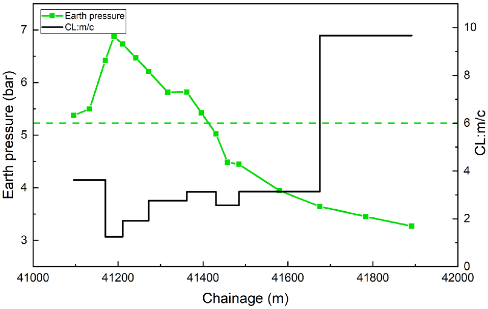
Statistics of earth pressure and cutter life.
The vertical pressure acting on the front face of the shield cutter head will increase with the increase in soil self-gravity stress ( 2 , 30 ). The external force experienced by the cutter ring also gradually increases, leading to an increase in the frequency of abnormal tool failures. The larger vertical and lateral stresses in the rock layer increase the contact stress between the rock particles and the cutter ring surface, resulting in increased abrasive wear on the surface of the cutter.
Cutter Wear Prediction and Verification
Two cutter wear prediction models are established to precisely select the cutter change position and the cutter inspection frequency. Based on the data of 1–450 ring statistics on the west and the theory of the response surface model, a cutter wear prediction model that considers normal and abnormal wear failures is established. This model considers the factors that influence the cutter life and predicts the average cutter life from a macro perspective. Based on the statistics of cutter uniform wear of 1–450 rings, the theory of abrasive wear, and the Colorado School of Mines (CSM) model, a uniform wear prediction model of the tool suitable for this stratum is established, which takes the cutter position and specifications into consideration. During shield tunneling, the above two prediction models can be combined to determine the position and frequency of opening the chamber and changing the tools. Engineers can control tunneling parameters and improve cutter design based on the weight of the influencing factors, to reduce cutter wear.
To explore the relationship of various influencing factors on cutter life in numerical terms, the data are analyzed in MATLAB. It is found that the linear correlation coefficients of earth pressure, thrust, uniaxial compressive strength, penetration, and torque with the cutter life are −0.798, −0.42, −0.77, 0.555, and −0.45, respectively. By means of stepwise regression, the factors that have great in fluence on collinearity are excluded. It is concluded that the factors that have obvious influence on the cutter life are earth pressure, shield thrust, and rock stratum uniaxial compressive strength. Under the assumption that the same kind of cutter is used, the above-mentioned statistically influential factors of the earth pressure, shield thrust, and rock stratum uniaxial compressive strength are used as independent variables while the cutter life CL(m/c) is used as the dependent variable. The response surface model is established, and the optimal regression equation is obtained as below:
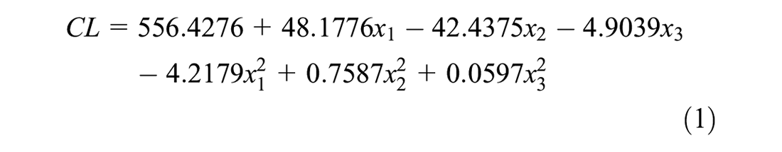
where
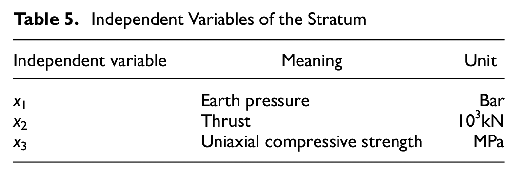
The independent variables and their units are shown in Table 5. The variance of the model is 0.9908, indicating that the fit is good, and the error is small. Because of the relatively single strata and the small changes of uniaxial compressive strength, the rock uniaxial compressive strength has a smaller weight in the model. The comparison between the predicted results and the measured values of the east-line is shown in Figure 18. The standard error between the predicted value and the actual measured value is 0.1. The error is acceptable, indicating that this prediction model can be used for the prediction of future excavation construction.
Independent Variables of the Stratum
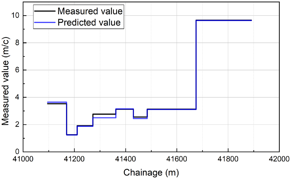
Comparison of predicted cutter life and measured data.
In relation to uniform wear, the CSM model as shown in Equation (2), has been widely applied (31):

where
W (kN) = the vertical force of rock breaking by cutter,
C = the dimensionless coefficient, taking 2.12,
R0 (mm) = the cutter radius,
T (mm) = the blade width,
ψ = the pressure distribution coefficient of the top edge of the cutter ring (generally 0.2 to −0.2),
φ (°) = the contact angle of the cutter,
S (mm) = the blade distance,
σc (Mpa) = the uniaxial compressive strength of rock, and
σt = the shear strength of rock.
Based on the Rabinowicz’s abrasive particle wear equation and the CSM disc cutter rock breaking force model, a disc cutter radial wear rate model is proposed ( 31 , 32 ).
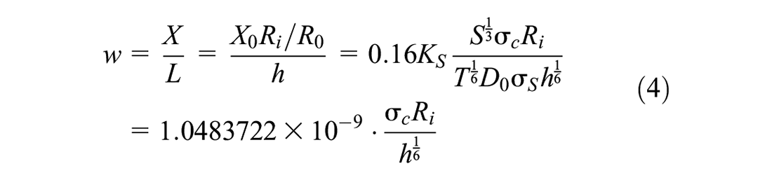
Radial wear of the hob ring under the unit tunneling distance, w, is as follows:

where
L (mm) = the driving distance,
Among them,
As shown in Figure 19, the above wear prediction model was used to predict the wear of 367 rings in the east-line tunneling, and the results were compared with the measured cutter wear data. The overall trend of the predicted wear of the front cutter is in good agreement with the measured value, which means that this model can be used to predict the cutter wear in a later period. However, additional data and analysis are still needed to optimize and improve the prediction model. The wear of the S 25, S 33, and S 44 cutters on the same cutter arm is greater than the wear of similar center distance cutters. The wear of the S 18, S 26, and S 34 cutters of the same cutter arm is relatively small. The above phenomenon indicates that part of the cutter head is unevenly worn and the slag discharge path is not smooth. Some of the cutters on the cutter arms chipped repeatedly and broke rocks, while the cutters on the other cutter arms did not work properly, resulting in uneven tool distribution. From past projects, if the slag improvement and the improvement of abnormal wear failure of the tools are carried out in future projects, it is expected that the problem of uneven cutter wear could be improved.
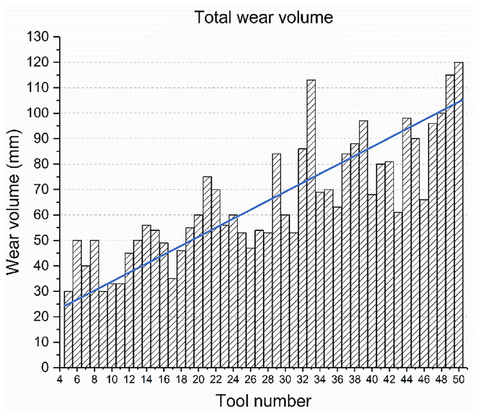
Comparison of S 5–S 50 disc cutter uniform wear prediction data with measured data.
Conclusions
From the analysis of the cutter wear data of the Guangfo East Ring Tunnel and combination of geological parameters and operational factors of the section, the following conclusions are obtained:
Cutter wear is related to cutter properties, stratum conditions, and tunneling parameters. Cutter wear mechanisms include abrasive wear, adhesive wear, fatigue wear, and oxidation. The main failure type of disc cutters is uniform wear failure, while the damage caused by abnormal failure disc cutters cannot be overlooked.
According to the statistics of cutter change data, the abnormal wear proportion is 23.28%. Abnormal wear is serious, while the proportion of partial wear is the largest. The uniform cutter wear increases with the center distance. The selection of the proper cutter distance can reduce the disc cutter wear.
There is a correlation between the disc cutter wear and shield tunneling parameters. Appropriate penetration can reduce cutter wear, while a very large or small penetration will have adverse effects. There is a negative correlation between the cutter life and the compressive strength of rock strata, and between the cutter life and earth pressure. It is necessary to increase the frequency of cutter inspection and change cutters in time in rock strata with greater compressive strength and deeper tunneling sections.
Based on the response surface model theory, a cutter life prediction model was established for siltstone strata, considering the compressive strength, earth pressure, and shield thrust of the strata. Linear regression analysis shows that the abrasive wear coefficient of this siltstone section is 1.49364 × 10⁻³. Based on the Rabinowicz abrasive wear equation and the CSM model, a disc cutter wear rate prediction model for the frontal area was established. Two prediction models can be combined to determine the cutter change position and frequency so that the time spent on cutter inspections can be reduced. Based on various influencing factors, the improvement measures to reduce cutter wear can be further explored.
Footnotes
Author Contributions
The authors confirm contribution to the paper as follows: study conception and design: X. Li, J. Wu and P. Su; data collection: Z. Gong; analysis and interpretation of results: J. Wu, P. Huo; draft manuscript preparation: X. Li, J. Wu. All authors reviewed the results and approved the final version of the manuscript.
Declaration of Conflicting Interests
The author(s) declared no potential conflicts of interest with respect to the research, authorship, and/or publication of this article.
Funding
The author(s) disclosed receipt of the following financial support for the research, authorship, and/or publication of this article: This research was funded by the National Natural Science Foundation of China (No. 51808469), Shanghai Key Laboratory of Rail Infrastructure Durability and System Safety (No. R201902), and The Basic Applied Research Projects of Sichuan Science and Technology Department (No. 2022NSFSC0442).