
Abstract
Recently, there has been wide concern about the mechanical properties of the repair interface for the magnesium phosphate cement mortar as a repair material with Portland cement concrete pavement. In this paper, based on the previous research results about basalt fiber reinforced and polymer modified magnesium phosphate cement (BFPMPC) mortar, the fracture behavior of the interfacial transition zone (ITZ) for BFPMPC and Portland cement concrete (PCC) was further pursued and studied. Firstly, a nanoindentation test was carried out on the repair interface with creep characteristics. Results showed that a synergistic effect and elastic moduli of multiple ITZs in repair interface were verified and determined. Then, the creep characteristic of ITZ was described by proposed fractional rheology characteristics in BFPMPC-PCC ITZ with further validation by finite element analysis. Finally, the interface fracture model combined with dislocation theory was proposed and analyzed. The results showed that satisfactory agreements had been obtained between the calculated results of interface fracture model and experiments. It was indicated that the fracture essence for BFPMPC-PCC ITZ was revealed by the interface fracture model. This finding, as a novel aspect and insight for interface fracture of bi-cementitious-based materials, was provided and the pursued direction of materials design for interface enhancement in pavement rapid repair was expected.
Keywords
At room temperature, dead burnt magnesia (MgO), potassium dihydrogen phosphate (P), and water undergo an acid-base neutralization reaction to form a mixture, magnesium phosphate cement (MPC), an efficient fast-hardening cementitious material ( 1 ). Compared with ordinary Portland cement (OPC), the operation process of MPC is relatively simple, the hydration product has excellent characteristics, and it is frequently used as ceramic material. Studies on MPC have demonstrated that strengths are dependent on fineness and calcination temperature of MgO, the molar mass proportion of P/Mg, retarder content, mineral additives content, and so forth ( 2 – 7 ). MPC could also be strengthened by polymers and fibers to enhance crack resistance ( 8 , 9 ). By adding mineral additives to MPC, the water stability and acid-based corrosion resistance are improved ( 10 , 11 ). MPC also has the ability to develop strength rapidly, to be thermally stable, frost resistant, and salt corrosion resistant, and to have good structural stability (8, 12–14). Furthermore, a broad application prospect must be pointed out, that adding various industrial wastes into MPC-based materials also is in line with low-carbon impact development strategies and is strongly advocated ( 15 – 17 ).
In recent years, for engineering application, MPC has been often used as a popular repair material in pavement and structural engineering. As early as 1993, Seehra et al. used MPC to repair concrete slab cracking and potholes (shallow and deep), and to seal cracks in Portland cement concrete pavement (PCCP), reopening traffic for highways and airports after 4–5 h ( 18 ). Consequently, the processing performance, mechanics properties, and cost of MPC have been optimized in the laboratory. It can be proved that the overall performance with absolute advantages for MPC in pavement rapid repair is better than the other cementitious materials ( 19 ). Durability such as volume stability, shrinkage performance, bonding strength, ice resistance, and abrasive resistance are indexes to evaluate the feasibility of MPC as a repair material for cement concrete infrastructures ( 20 – 29 ). In addition, the performance and durability of MPC mortar used for rapid repair of PCCP in coastal and seasonally frozen areas were comprehensively studied by Liu et al. ( 14 ). It was found that the MPC can repair corner cracks, potholes, and other distresses of PCCP effectively, and reopen to traffic after 6 h.
Then, the essential problem is that, as the vehicle load acts on the MPC repair area, the repair interface suffers from shear damage in the vertical direction. This seriously affects the repair life of MPC. Therefore, the durability of MPC repair interface should be further studied. Concrete structures are known to suffer from damage, fracture, and so on, in their interfacial transition zone (ITZ), which usually is the cause of their poor performance ( 30 – 33 ). Thus, as a result of the mechanical properties of the repair interface, the quality and effectiveness of the repair are determined ( 34 – 36 ). Simultaneously, by analyzing the interface between MPC and old concrete matrix, Qin et al. investigated their bonding behavior and microscopic characteristics ( 24 ). First of all, MPC has high bonding strength and affinity, as well as relatively developed microscopic structure at its interface. Additionally, various kinds of interface interactions between MPC and concrete existed and were observed. Through soluble phosphate penetration, chemical reaction and filling effects were possible at the interface. The results of this research not only provide an understanding of how MPC interacts with old concrete at the repair interface, but also provide a useful scientific basis for further studies.
Notably, the results of many studies showed that creep has a significant impact on the mechanical and deformation properties of concrete structures, especially for the interface in cement concrete ( 37 , 38 ). The fracture behaviors of the rock-concrete interface under continuous loading through many creep experiments with different interface sizes and load levels were investigated by Dong et al. ( 39 ). Conventional creep experiments usually use time-consuming macroscopic mechanical experiments to characterize the cement material properties ( 40 , 41 ). However, nanoindentation creep research is a time-saving and convenient test method at the microscopic level, and has been widely used to study the creep characteristics of cement materials in recent years. However, there are few studies on the creep characteristics of MPC, let alone the interface between MPC and cement concrete.
Additionally, the theoretical framework of linear rheological models has been established and perfected, as an important role in practical engineering application in recent years. However, if the viscosity of materials, such as cement, and so forth, is extremely large from fluid to amorphous structure with limitation of the conventional linear rheological model used to describe the deformation law, the description of the creep process will become more complex ( 42 – 44 ). Recently, some experimental and simulation studies indicated that the atomic arrangement of amorphous structure was not absolutely disordered while within a certain short or medium-range order ( 45 – 47 ). It was more reasonable to use the solute atomic-centered atomic cluster model to analyze the microstructure of amorphous structure. Therefore, the fractal properties of materials were fully reflected by the fractional rheological model ( 48 ). It was also introduced to describe the rheological mechanical behavior of amorphous structure, which can better interpret the micro heterogeneous evolution behind it, especially for cement from flow to hardening with hydration. Results were reported that the nanoindentation creep behavior of amorphous structure was verified. It used the fractional Kelvin model to describe the shear transformation zone, and the fractional order elastic dashpot to describe the plastic yield flow. Finally, the reproducible viscoelastic deformation and non-reproducible viscoplastic flow behavior of amorphous structure during the nanoindentation creep process were respectively fitted and analyzed. This provides a very useful hint and inspiration for this study.
Objective and Scope
As a novel type of pavement rapid repair material, BFPMPC mortar was proposed in previous studies ( 14 ). The mechanical properties of the repair interface as a decisive factor were determined by the durability of BFMPC as a pavement repair material. However, little attention was paid to describing the fracture property of repair interface. Therefore, the objective of this paper is to further study the interface fracture between BFPMPC and Portland cement concrete (PCC). Firstly, nanoindentation experiments were used to measure the elastic modulus and creep parameters of ITZ, then the elastic modulus of each inclusion phase in ITZ were calculated by deconvolution. Secondly, combining the proposed modified and generalized Kelvin model with the fractional rheological model to characterize the creep characteristics of interface, then finite element modeling (FEM) about nanoindentation (FEM-nanoindentation) was used to validate it. Subsequently, the proposed modified and generalized Kelvin model with fractional rheological model was used as material constitutive model of ITZ. Thirdly, a derivation procedure by dislocation theory was used to propose the interface fracture model as suited to the interface of BFPMPC and PCC. Then, the FEM about plain interfacial shear strength test was used to verify the correctness of the fracture model. Finally, the experimental, equational, and FEM (FEM-shear strength test) results were compared to estimate the feasibility of the proposed interface fracture model.
To highlight the objective and research significance, the study roadmap is shown in Figure 1.
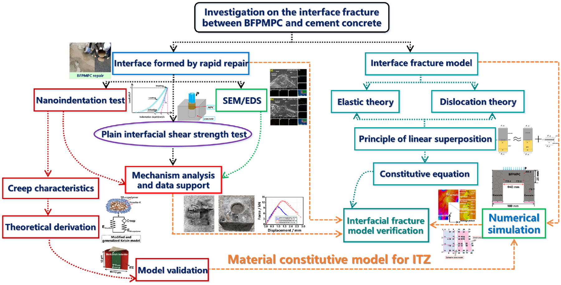
Study roadmap on interfacial fracture between basalt fiber reinforced and polymer modified magnesium phosphate cement (BFPMPC) and Portland cement concrete (PCC).
Materials and Methodology
Raw Materials and Sample Preparation
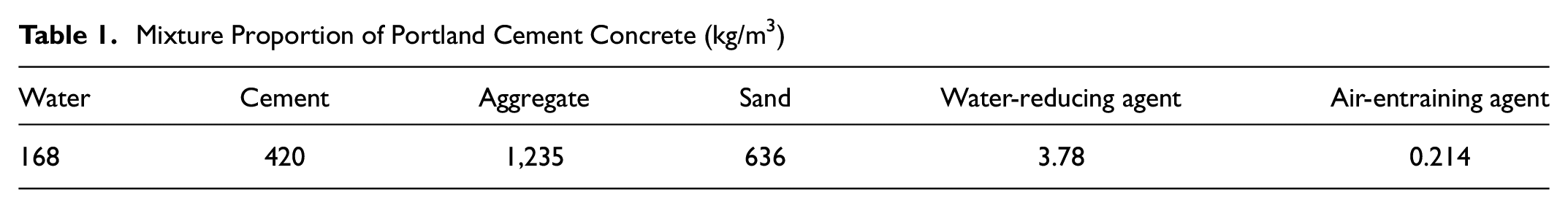
In this study, PCC was cut from old cement concrete pavement slabs. In PCC, the coarse aggregate was basalt. The fine aggregate used was a natural siliceous sand (river sand). Figure 2a shows aggregate gradation curves. The fine aggregate used in this study was 9.5 mm in particle size and 2.81 in fineness modulus. Dalian Onoda Cement Factory provided the cement type P·O 42.5R to study. Figure 2b shows the particle size distribution of cement. The mixture proportion of old concrete is shown in Table 1 with a 0.4 water-cement ratio. The water-reducing agent and air-entraining agent were used in the concrete, as shown in Table 1.
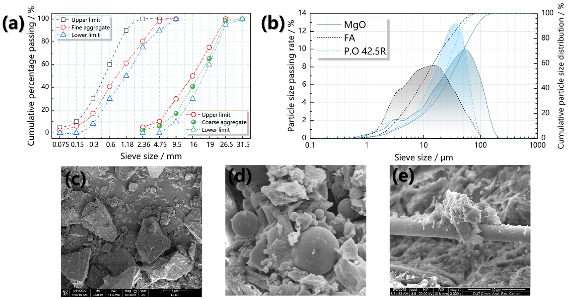
Basic information for raw materials: (a) gradation curves of fine and coarse aggregate, (b) particle size distribution curves of MgO, FA, and P.O 42.5R type cement, (c) microscopic diagram of MgO, (d) microscopic diagram of fly ash (FA), and (e) microscopic diagram of basalt fiber.
Mixture Proportion of Portland Cement Concrete (kg/m3)
The BFPMPC system was designed to use dead burnt magnesia (MgO, M) from Xinhe Magnesium Products Factory in Haicheng, Liaoning Province China. Figure 2, b and c , shows the particle size distribution and microscopic picture of dead burnt magnesia. Potassium dihydrogen phosphate (P) with a purity of 99% could be easily decomposed when heated. To slow down the setting speed of MPC, Borax (Na2B4O7·5H2O, B) with purity of 99.5% was chosen as the retarder. Class-F fly ash (FA) produced by Gongyi No. 2 Power Plant, China, was used. A microscopic picture of FA, as well as particle size distributions, can be seen in Figure 2, b and d . Table 2 shows the chemical analysis of dead burned magnesia and FA which was conducted using X-ray fluorescence spectrometry. The type of ECO 7623 styrene butadiene copolymer emulsion produced by BASF of Germany was used. Basalt fiber with a length of 12 mm and a diameter of 17.4 μm was produced by Shanghai Chenqi Chemical Technology Co., Ltd in China. The microscopic picture of basalt fiber is shown in Figure 2e. Test results show the mixing proportion of BFPMPC mortar as a repairing material in Table 3 ( 14 ).
Composition Parameters of Dead Burnt Magnesia and Fly Ash (FA) (wt. %)
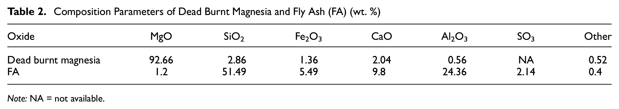
Note: NA = not available.
Mixture Proportion of Basalt Fiber Reinforced and Polymer Modified Magnesium Phosphate Cement (BFPMPC) Mortar (kg/m3)
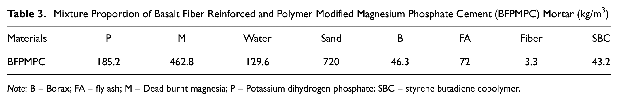
Note: B = Borax; FA = fly ash; M = Dead burnt magnesia; P = Potassium dihydrogen phosphate; SBC = styrene butadiene copolymer.
To investigate the interfacial shear fracture behavior for BFPMPC and simulate the fracture stress state for the repairing potholes on PCCP, the composite BFPMPC-PCC specimens were prepared. First, the PCC cut from pavement slabs was fabricated as geometric blocks with length × width × height = 100 × 100 × 80 mm. Next, a 40 mm diameter cylinder was cut off at the geometric center from the surface (100 × 100 mm) of the concrete block to form a hollow concrete block. Then, the BFPMPC was poured and condensed into the potholes to simulate the repair of corner cracking and potholes in PCCP, and placed in the curing room for 6 h and 3 days with air curing (temperature: 20°C ± 5°C, relative humidity: 50% ± 5%). Specimens were composed of BFPMPC at curing ages of 6 h and 3 days and old PCC, which were named BFPMPC-PCC-6 h and BFPMPC-PCC-3 days, respectively. After curing, the three duplicated composite BFPMPC-PCC specimens of 6 h and 3 days were prepared to test plain interfacial shear strength ( 14 ).
Methodology
Multiple Interfaces in BFPMPC Repairing
It is possible for the aggregate surface of concrete to be exposed as a result of distresses such as slab corner cracks and potholes, as shown in Figure 3a. After repairing, the BFPMPC mortar bonded to the exposed concrete surface, as shown in Figure 3b. Therefore, various ITZs can be formed on the repair interface, as seen in Figure 3c. Consequently, a conceptual image of interface study was presented in this paper, as shown in Figure 3d. To facilitate distinction, all ITZs are explained as follows:
(i) ITZ-1 is the interface between coarse aggregate and cement mortar in concrete;
(ii) ITZ-2 is the interface between BFPMPC paste and OPC paste;
(iii) The interface between BFPMPC paste and ITZ-1 is ITZ-3;
(iv) The interface between BFPMPC paste and exposed coarse aggregate is ITZ-4.
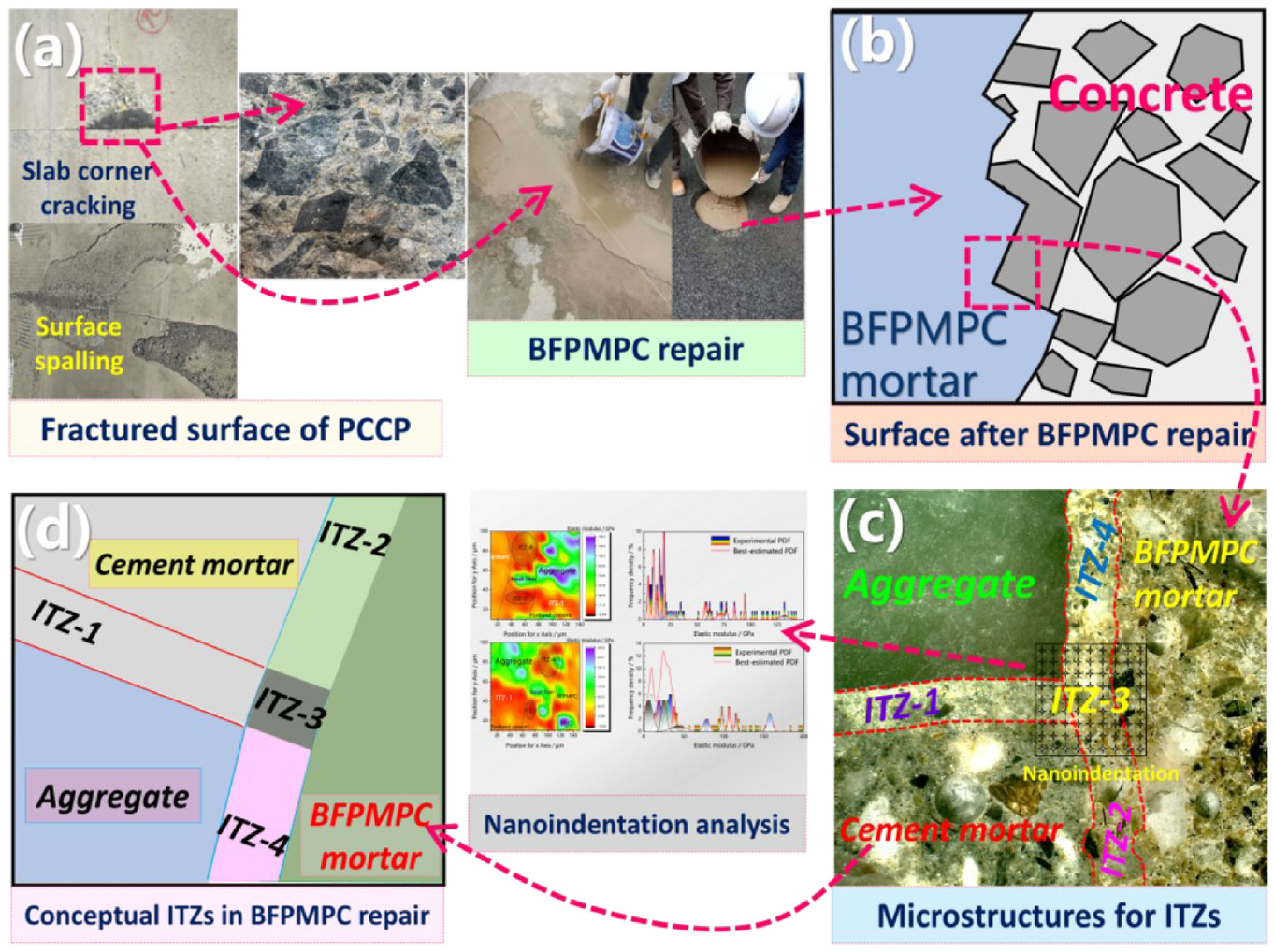
Multiple interfaces in basalt fiber reinforced and polymer modified magnesium phosphate cement (BFPMPC) repairing: (a) exposed concrete by potholes, slab corner cracking and surface spalling, (b) surface of cement concrete after rapid repaired by BFPMPC, (c) repaired interface, and (d) conceptual image of interfaces.
Plain Interfacial Shear Strength Test
The shear strength of the composite BFPMPC-PCC specimens prepared in Section Raw Materials and Sample Preparation were evaluated by plain interfacial shear strength test, as shown in Figure 4, which was conducted by Universal Testing Machine (UTM-100, Australia) with 100 kN maximum test load. The test diagram is shown in Figure 4. The loading mode was displacement controlled and the loading rate was 0.5 mm/min.
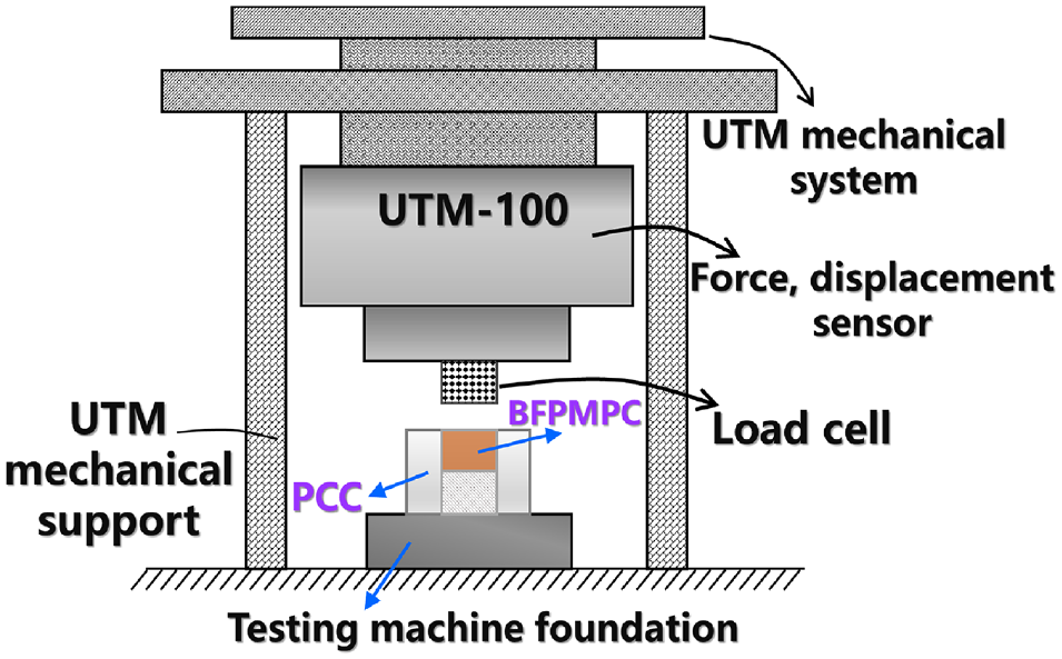
Test diagram for the plain interfacial shear strength.
Grid-Nanoindentation and Polishing Protocol
After testing the plain interfacial shear strength of composite BFPMPC-PCC specimens, the block about 10 × 20 × 20 mm containing BFPMPC and PCC was chosen to prepare for the nanoindentation experiment. Anhydrous ethanol was applied to the specimens for 24 h to stop hydration (to prevent further hydration to change the internal microstructure of cement products) before embedding with epoxy resin once they reached the test age (6 h and 3 days).
Before the above steps were completed, the polishing protocol was carried out. The specimens were first polished by silicon carbide papers with #250, #400, and #2000 for 5 min, and then polished by flannelette with 0.25 μm for 3 min before being placed in a drying box. Then, the necessary roughness test was the final guarantee for the accuracy of the nanoindentation test results in the polishing protocol. The roughness of sample surfaces for 6 h and 3 days measured by RH-2000 Digital Microscope, Tokyo, were 309 nm and 271 nm, respectively, which met the requirements of the nanoindentation test.
A total of 400 test points with 20 lines and 20 points on each line as a grid were tested. The nanoindentation is based on the Hertz contact theory ( 49 ). The indenter was pressed into the specimen surface to obtain the continuous load-indentation depth curves, as shown in Figure 5.
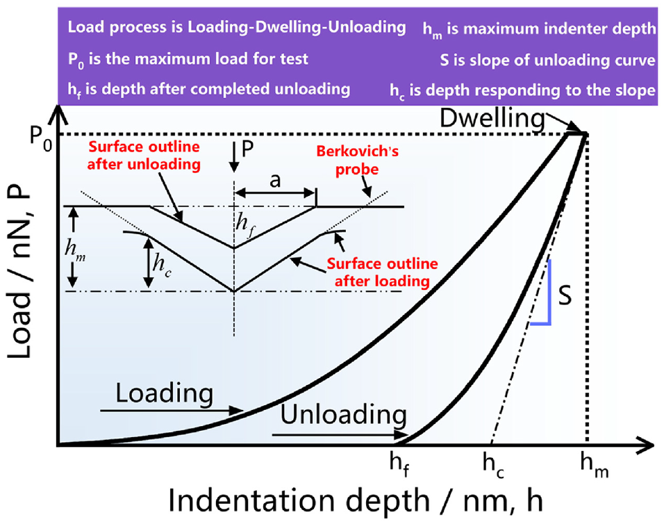
Typical nanoindentation test curve.
The nanoindentation instrument is HYSITRON® Triboindenter TI 980 with the standard BERKOVICH probe (θ = 65° and r = 150 nm, elastic modulus is 1,141 GPa, Poisson’s ratio is 0.07). The indenter was calibrated by indenting a calibration material (quartz) of known mechanical properties before testing. This loading method focuses on the elastic modulus and creep properties in this study. It can be seen in Figure 5 that the typical P-h curve with increasing loading was measured and followed by a short holding and decreasing unloading. The trapezoidal loading mode is as follows: loading, holding, and unloading ( 50 ). Li et al. used 180 s holding time to test the creep property of potassium magnesium phosphate cement ( 47 ). Liang and Wei used a holding time of 180 s to evaluate the creep property of hardened-cement pastes ( 51 ). Above all, the samples were loaded as: loading (load from 0 to 1,000/3,000/5,000 μN within 10 s); dwelling (load held 1,000/3,000/5,000 μN within 150 s for creep; 5 s for elastic modulus); and unloading (from 1,000/3,000/5,000 to 0 μN within 10 s). Then, the indentation modulus, elastic modulus, and hardness were reversely calculated by Equations 1 to 3.


where
A = The A is the contact area, which is determined by indentation depth (nm2)
In this paper, as the interface between BFPMPC and PCC is heterogeneity, the correction factor
Deconvolution Analysis
The cementitious material is a classical heterogeneous material which contains multiple inclusions phases and the mechanical properties of these were to abide by Gauss distribution ( 53 ). Therefore, each nanoindentation test data are treated as a single statistical event, and the data extracted by continuous indentation measurement analysis are characterized by random variables. From the point of view of statistical significance, to measure the elastic modulus of hydration products and other inclusions phases, the nanoindentation test was carried out based on the grid formed by at least 100 points at the microscopic scale. Results showed that 100 indentations are sufficient to ensure the convergence of elastic properties of low-density and high-density calcium silicate hydrate with an error of less than 5%. Therefore, in this study, there is a total of 400 test points as a grid 20 × 20 with length of 100 μm and width of 100 μm.
The nanoindentation results are analyzed by the discrete experimental distribution values
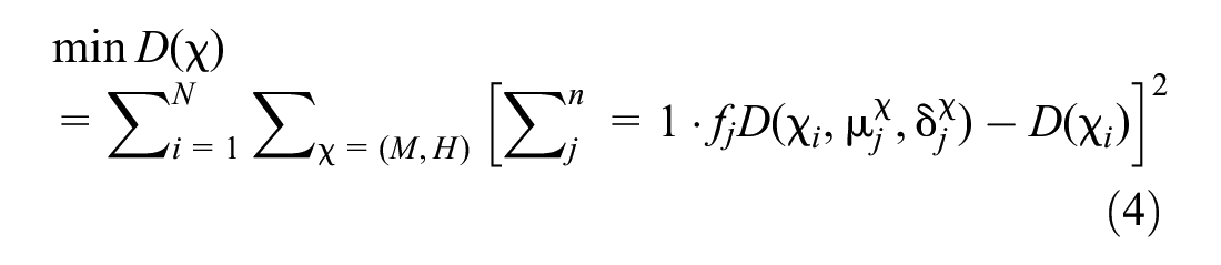
where
N = the number of intervals (bins) by each event is discretized,

For the multivariate distribution model, the minimum variance method can be used to deconvolve the Gaussian mixture function. The augmented filtering algorithm based on the linear minimum variance criterion is optimal. Based on the filtering algorithm, the optimal interval smoothing indirect algorithm and the optimal deconvolution estimation algorithm are proposed. The minimum variance method was used to analyze the nanoindentation measurements with different inclusion phases in this study.
Scanning Electron Microscopy/Energy-Dispersive Spectrometry (SEM/EDS)
FEI Nova NanoSEM 450 with scanning electron microscopy/energy-dispersive spectrometry (SEM/EDS) was used. The voltage was 3 kV, the beam spot was 3 mm, and the magnification was 2,500–1,0000 times of SEM. For EDS, the voltage was 20 kV and the beam spot was 5 mm. The microstructures and microscopic morphology of repair interface with the hydration products were observed and analyzed. The selected SEM/EDS sample was the interface specimen from the nanoindentation test.
Investigation of ITZs between BFPMPC and PCC
Nanoindentation
The elastic modulus of the ITZ with BFPMPC-PCC-6 h and 3 days are shown in Figure 6. The contour lines are drawn in Figure 6, a and c . The mechanical properties change of ITZs intuitively in the drawing of the contour diagram was observed by the annotation of the color card, as shown in Figure 6, a and c . Then, the deconvolution analysis was further conducted; the elastic modulus of multiple ITZs is shown in Figure 6, b and d .
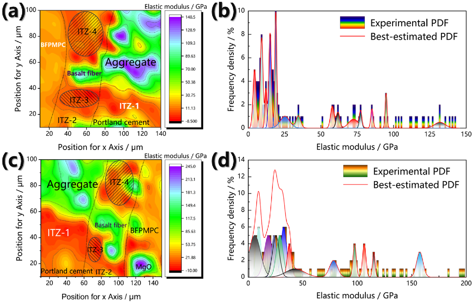
Contour lines of elastic modulus of Nanoindentation test and deconvolution analysis in interfacial transition zones (ITZs): (a) contour lines and (b) deconvolution analysis for basalt fiber reinforced and polymer modified magnesium phosphate cement-Portland cement concrete (BFPMPC-PCC)-6 h, (c) contour lines and (d) deconvolution analysis for BFPMPC-PCC-3 days.
The data in Figure 6, b and d , are integrated into Table 4 and compared with the references ( 54 – 61 ). All measured elastic moduli can be analyzed, as shown in Table 4. It can be seen from Table 4 that in the BFPMPC-PCC ITZ with 6 h and 3 days, the rank of elastic modulus was ITZ-2>ITZ-4>ITZ-1>ITZ-3 and ITZ-4>ITZ-2>ITZ-3>ITZ-1, respectively. This difference in relationship is because of the addition of polymer and fiber. OPC mortar has a rough surface and relatively loose structure compared with coarse aggregate. The surface of K-struvite was coated with polymer molecules in BFPMPC paste then contact with OPC mortar. Therefore, mechanical adhesion is easy to form on the relatively uneven surface, and the addition of polymer forms van der Waals force. The interface between BFPMPC mortar and OPC mortar is more compact, resulting in ITZ-2>ITZ-4. For the special position of the interface and wall effect, the hydration of BFPMPC paste in the interface is not completed. Furthermore, in the interface of BFPMPC-PCC, the K-struvite surface is coated by polymer molecules, which increase the bonding strength at the physical level. On the contrary, the various forms of silica-aluminum-calcium compounds with highly heterogeneous properties of OPC is to form an inferior mechanical interaction with BFPMPC pastes. Accordingly, the mechanical properties of the interface of OPC are worse than that of basalt aggregate with a dense and smooth surface. Therefore, the relationship of elastic modulus is ITZ-4>ITZ-2. In addition, the elastic modulus of ITZ between BFPMPC paste and basalt fiber at 6 h and 3 days was, 67.38 and 77.68 GPa, respectively. The mechanical properties of interface of basalt fiber were increased by curing age. This also illustrates that the BFPMPC pastes bonded to fiber closely with less defects.
Elastic Moduli from Literature and Deconvolution Analysis in Nanoindentation
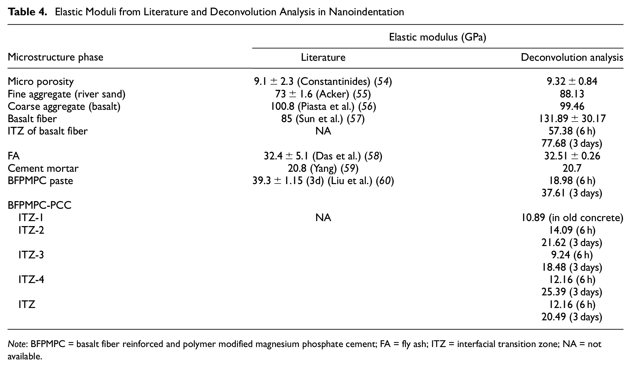
Note: BFPMPC = basalt fiber reinforced and polymer modified magnesium phosphate cement; FA = fly ash; ITZ = interfacial transition zone; NA = not available.
Creep Behavior and Fractional Rheology for ITZ
The creep characteristics for the test points of nanoindentation in ITZ were investigated, as shown in Figure 7 ( 62 , 63 ). The maximum load of the load-indenter depth curves was 3 mN for the nanoindentation test. To further explore the creep property of ITZ, the maximum indentation force was changed to 1 mN, 3 mN, and 5 mN for testing, respectively, at different loading rates (0.1, 0.3, and 0.5 mN/s). The holding load was retained for 150 s and then unloaded to 0 at the same rate as the loading rate during the nanoindentation experiment. To reduce experimental error, the sample was frequently tested at three points under the same conditions.
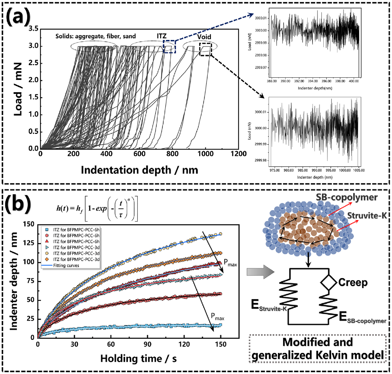
Creep test and fractional rheology verification for interfacial transition zone (ITZ): (a) creep in the ITZ and (b) modified and generalized Kelvin model for ITZ of basalt fiber reinforced and polymer modified magnesium phosphate cement-Portland cement concrete (BFPMPC-PCC).
Significantly, for the weak mechanical properties, the indentation depth of BFPMPC-PCC-6 h interface was larger than that of 3 days with the loading process of nanoindentation, as can also be seen in Figure 7a. With the increase in loading, more rheological units were activated in the process. However, the activated rheological units cannot be released in the loading stage and can be fully developed in the loading stage for the short reaction time at a high loading rate, and the above deformation law under different conditions was shown.
Creep recovery existed in ITZ for nanoindentation experiments, especially for plastic, viscoelastic-plastic, and elastic-plastic materials ( 51 ). For material constitutive traceability, the modified and generalized Kelvin model can describe the properties of BFPMPC paste, as shown in Figure 7b. The main hydration product, K-struvite, was coated by polymer molecules, which decomposed the mechanical behavior into recoverable viscoelastic deformation and non-recoverable viscoelastic flow behavior.
The fractional differential theoretical framework was defined by Riemann-Liouville ( 64 ). The mechanical response of the model in Figure 7b can be expressed as Equation 6:

where
In general, creep compliance can be derived from creep data. The relationship between strain and creep flexibility can be described as follows, in Equation 7:

According to the above mechanical response model and Laplace transform, the creep modulus
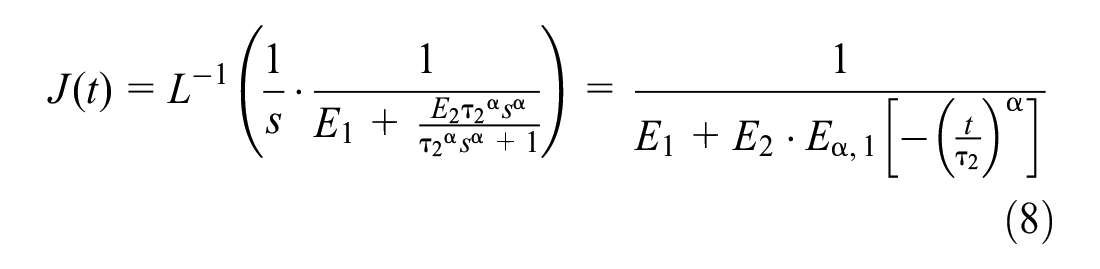
Then, the relationship between strain and time can be written as Equation (9):
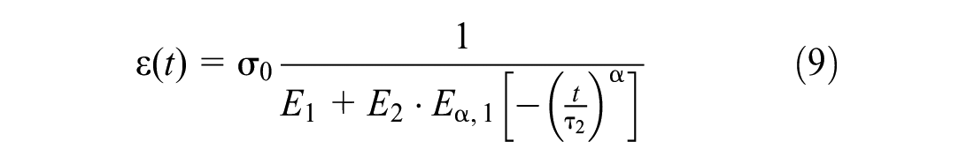
Notably, the Mittag-Leffler function exists in the above formula ( 65 ):
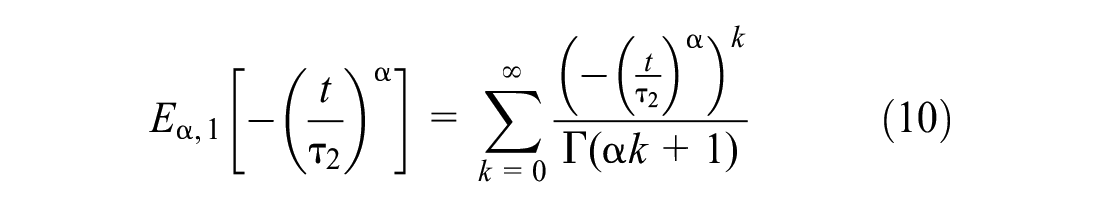
For a summation of infinite series, to avoid truncation error and non-convergence of series, the

Therefore, the strain as a function of time can be written as Equation 12:

However, the strain is also a function that changes with depth. According to P-Oliver theory, the strain function can be written as Equation 13 ( 49 ):


Therefore, the relation between creep displacement and time can be expressed as Equation 15:

The upper limit of this integral is that the depth reaches the maximum depth

where
Then, the depth of the creep part is expressed as Equation 17:

To verify the correctness of the model, the creep data of nanoindentation is extracted and analyzed, as shown in Figure 7b. The fitting model for the curves is shown in Table 5. As the nanoindentation holding force increases, the maximum indentation depth also increases. The value
Validation of Fitting Model with Different Maximum Loads
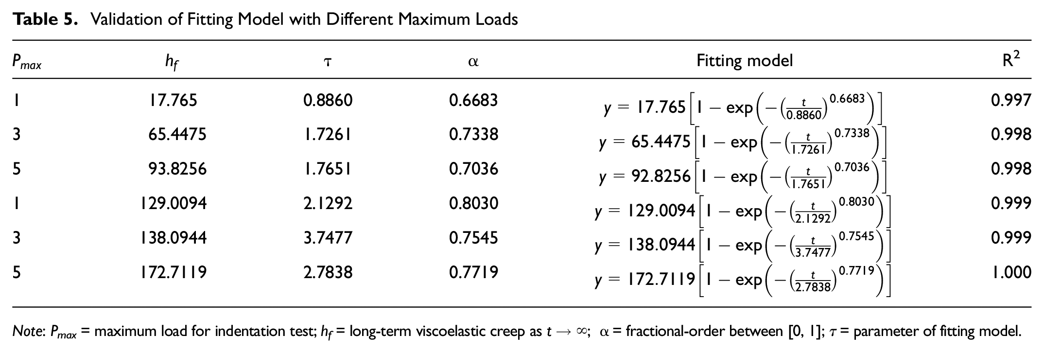
Note: Pmax = maximum load for indentation test; hf = long-term viscoelastic creep as
Validation of Modified and Generalized Kelvin Model
Numerical Simulation Illustrations
For the simulation of nanoindentation, the commercial software ABAQUS/ STANDARD 2021, Dassault Systems SIMULIA, Providence, RI., was implemented to establish the FEM-nanoindentation. Considering the maximum inputting depth of 3,000 nm and the required size of the indenter, an ITZ model with a diameter of 13 μm and a height of 10 μm was established. Concerning the symmetry of the model, half of the original size of the model was used to improve computing efficiency. The hardness and elastic modulus of Berkovich’s indenter was considerably higher than the properties of the ITZ to be tested, resulting in it setting as a rigid body, which guaranteed the simulation accuracy and decreased the computation time and memory allocation. The ITZ sample was treated as a solid with uniform material distribution and followed the von Mises yield criterion and isotropic criterion. Parameters of material constitutive model for ITZ were derived from Section Creep Behavior and Fractional Rheology for ITZ. Nevertheless, considering that the test points in the 40 μm broad ITZ area were tested by lattice and each test point has differences, the subsequent work will likewise consider the interaction of different micro-areas, as shown in Figure 8.
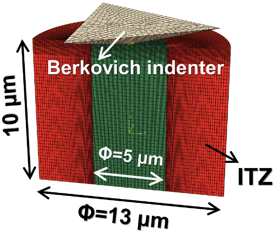
3D nanoindentation model for creep simulation.
The ITZ elastic-plastic constitutive model was the von Mises continuous plastic yield model. Von Mises yield strength, as a deformation, is generally considered to be the result of pressure action, in the following form:
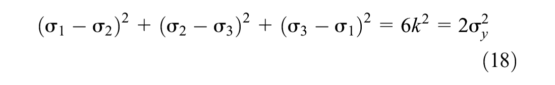
where
Based on the literature, the average coefficient f = 0.15 was selected to simulate the contact friction in the indentation process ( 66 , 67 ). For the boundary conditions, the bottom surface was set as fixed (U1=U2=U3=UR1=UR2=UR3=0), the around surface was free in all directions, and the plane side of the sample was set as free in the y-direction (U1=U3=UR1=UR3=0).
Simulation Results
At the beginning of the indentation, the ITZ surface was pressured. The nephogram of nanoindentation without indenter is shown in Figure 9a. When the indenter was pressed into the maximum depth, the crack appeared; the nephogram is shown in Figure 9b. The main view of the nanoindentation simulation with indenter is show in Figure 9c. Notably, cracks appeared at the edge of the indentation and below the edge of the indenter, which was consistent with the results of previous studies on MPC ( 47 ). The creep recovery in the unloading stage was consistent with the experimental results, as shown in Figure 9d. It was found that, when the force was loaded to 3 mN, the results of numerical calculation were consistent with the experimental results, resulting in a satisfactory agreement of loading, load retention, and unloading parts. This verifies that the constitutive theory proposed in this section is suitable for the study on creep characteristics of ITZ. Then, the interfacial shear constitutive model of ITZ formed by BFPMPC and PCC can be modified, which is described in the following Section Interface Fracture Model for BFPMPC-PCC.
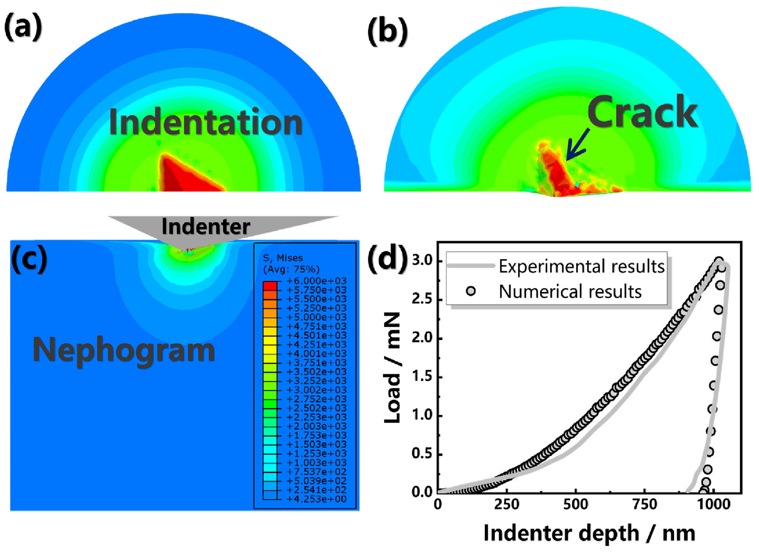
Numerical and experimental results for the nanoindentation: (a) the beginning of the indentation, (b) crack in the indentation, (c) nephogram for the simulation, and (d) curves of the test and simulation.
Interface Fracture Model for BFPMPC-PCC
Analytical Solution of Interface Fracture Model
Before this, a comprehensive understanding of the interface properties of BFPMPC-PCC should be obtained, including the elastic modulus and creep. As a product on the BFPMPC, the paste achieved the extreme performance of strong bonding force between two different materials with regard to physical occlusion and chemical bond attraction. This is confirmed by the microphysical and mechanical experiments. The performance of BFPMPC is better than PCC in plain shear strength and three-points bending strength. BFPMPC shows satisfactory physical bonding because of the addition of polymer. The analysis from the previous nanoindentation experiment showed that the repair interface has strong mechanical properties. If the interface performance is weak, the energy transferring to this point can cause rapid fracture failure. Therefore, the ITZ plays a vital role in bridging interface fracture. For the ITZ as a crucial layer, the classic sandwich model is strictly defined in this paper. On this basis, a modified constitutive model of the ITZ was proposed so that the change of complex stress and strain near ITZ was described.
In Section Validation of Modified and Generalized Kelvin Model, the creep characteristics on ITZ between BFPMPC and PCC has been confirmed, resulting in the exploration of the constitutive model of ITZ being developed in a positive direction. To solve the deviation of stress analysis in the ITZ between BFPMPC and PCC, a classic sandwich model was established for analysis and calculation in the Appendix. Notably, some assumptions were established in this study. In previous studies, the defects in the micro zone are the main reason for the weakening of the mechanical properties of the ITZ, which is always born on the side of BFPMPC ( 68 ). In the microscopic area, the performance weakening area is formed as a result of the difference in material properties, and then it also becomes an inevitable defect in the structure. BFPMPC and PCC were established on both sides of ITZ, and representative volume element (RVE) was assumed. Then the stress at any point in the ITZ was affected by the elements around it, and the stress and strain with damage were transmitted in it.
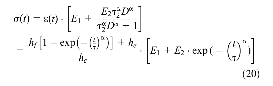
Consequently, the damage to ITZ was reasonably deduced. Firstly, the modified and generalized Kelvin model proposed previous needs to be introduced. Thus, the expression of depth concerning time

The expression of stress and time is transformed in Equation 20 as follows:
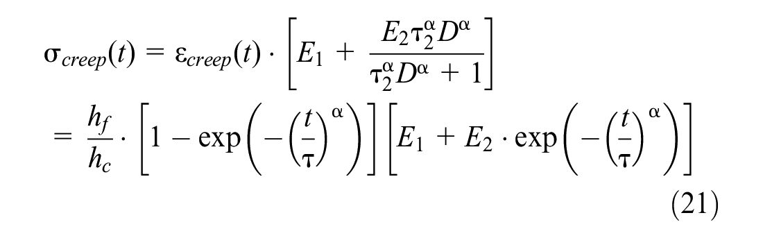
The form of creep stress generated in the creep process can be written as Equation 21:
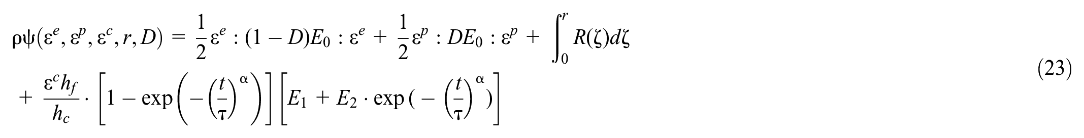
The damage factor in Equation 22 is introduced to describe the progressive damage in the ITZ.

where
The thermodynamic forces
where
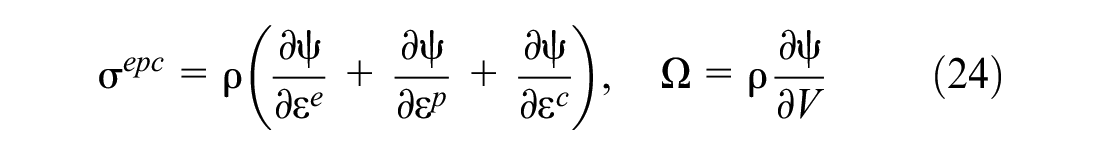
where
In previous studies, the damage factor

The total area

The above Equations 25 and 26 reflect that, in fact, in the ITZ, the total load
Therefore, on any plane in the ITZ, the F is shown in Equation 27:

The damage factor of any plane can be written as Equations 28 and 29:


After defining effective stress, it is found that, when damage occurs, the stress is written as Equation 30:

For predicting the properties of RVE of the sandwich structure, the relative thickness of ITZ in the following three situations was analyzed: BFPMPC:ITZ:PCC = 0.4:0.2:0.4, BFPMPC:ITZ:PCC = 0.3:0.4:0.3, and BFPMPC:ITZ:PCC = 0.35:0.35:0.3 ( 64 , 69 , 70 ). The modified interfacial shear model for the analytical results in different cases is shown in Figure 10.
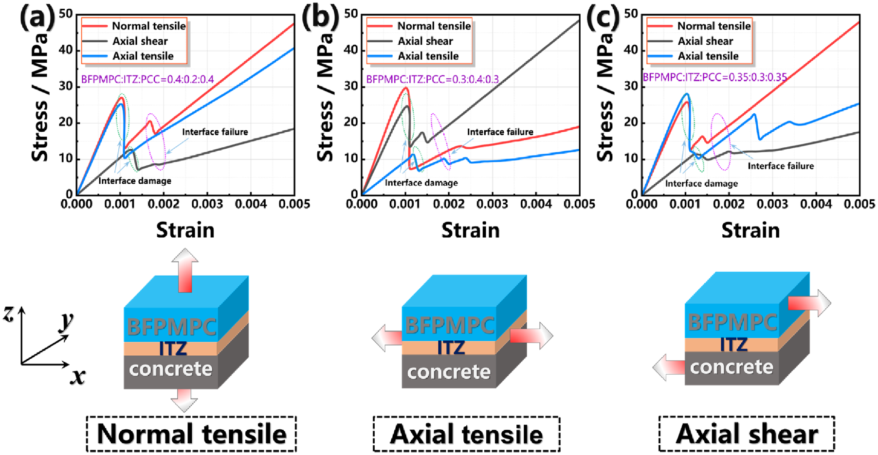
Modified interfacial shear model for the analytical results: (a) normal tensile, (b) axial tensile, and (c) axial shear.
As can be seen from Figure 10, the simulated results also expressed the influence of the thickness of the ITZ on the interface fracture. The thicker the interface, the worse the fracture resistance. This is closely related to the poor mechanical properties of ITZ. The width of interface was smaller, resulting in the sandwich structure was more difficulty to failure. Thus, in order to improve the repair interface, it was also necessary to minimize the thickness of the ITZ, which was also one of the key research directions for the interface between BFPMPC and PCC.
Comparing the stress-strain curves of sandwich structures with different ITZ thicknesses in Figure 10, axial shear was the most obvious mode for causing structural damage. As the only structure connecting BFPMPC and PCC on both sides, the ITZ was directly affected by its mechanical properties. For the curve of axial shear failure in Figure 10, a–c, it can be found that the softening behavior after the interface shear failure was caused by the polymer and fiber. While the two softening stages are shown in Figure 10b, it can be concluded that the possibility of fibers was increased by the width of ITZ. The interface for the shear failure of BFPMPC matrix failed first, then the fiber interface shear fracture occurred, resulting in a softening stage increase.
The strong bonding between BFPMPC and PCC was reflected by the normal tensile curve. Similarly, the larger the ITZ thickness, the weaker its resistance to normal tensile failure. It can also be seen from Figure 10a that the fracture occurred within a small strain range, as the interface width was thinner. As the interface was thicker, the fibers may be pulled out, which further weaken the interface performance.
Validation of FEM of Shear Strength Test and Discussion
For numerical simulation, the two-dimensional FEM of shear strength test with randomly polygon aggregates was established by ABAQUS and developed secondarily with Python 3.8, as can be seen in Figure 11. The geometry used the fully integrated plane strain, quadratic, and quadrilateral elements. Additionally, at an intermediate position between BFPMPC and PCC, a zero-thickness ITZ plane with assumed crack was established. In Figure 11a, The boundary conditions for the infinite stiffness of the bottom and surrounding surfaces of PCC were set. The bottom surface of the PCC was fixed, the horizontal and vertical displacement was zero, and rotation was zero. However, the displacement and rotation for BFPMPC and concrete inner hole surface was freedom. The geometry of the model was 80 × 100 mm with 40 × 25 mm of BFPMPC. Notably, about the FEM, a total of 670,000 degrees of freedom and approximately 15,000 quadratic quadrilateral elements with full integration are employed, as shown in Figure 11b. At the vertical direction, the BFPMPC had the maximum displacement of 2 mm. The uniform load was applied to the upper surface of BFPMPC, and the loading rate was 0.5 mm/min.
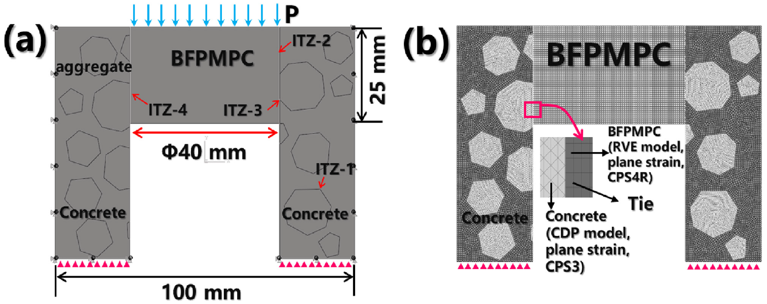
Numerical modeling for plain interfacial shear strength test: (a) simulation model with geometric dimension, boundary conditions and force and (b) element types for the model.
For BFPMPC-PCC, the concrete damage plasticity (CDP) model was used to describe the concrete with nonlinear behavior, as shown in Table 6 ( 71 ). In addition, the basic mechanical properties of BFPMPC mortar are shown in Table 6.
Parameters of Material Constitutive Models for Finite Element Modeling (FEM) Simulation
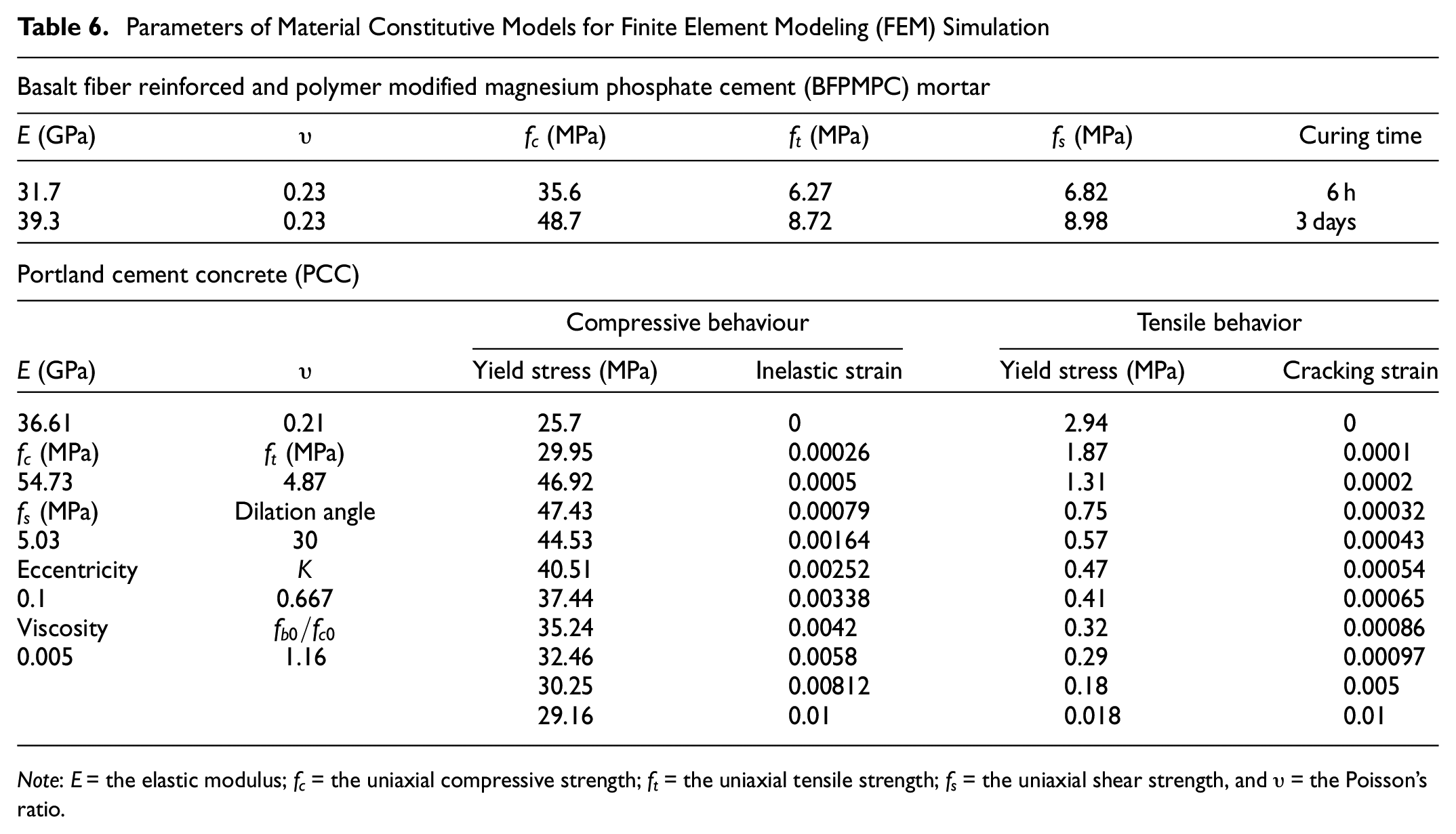
Note:
Numerical simulation results of FEM are shown in Figure 12. For BFPMPC-PCC 6 h and 3 days, as BFPMPC subjected to axial loading, the obvious mechanical response was shown by both sides of the repair interface, especially at ITZ-3. In Figure 12, in the repair interface, a larger interfacial shear stress appeared in the area around ITZ-3. The crack extended from the end of the repair interface to ITZ-3 until the fracture, as shown in Figure 12, a and b . Because of the special position and structure, the mechanical properties of ITZ-3 were weak and easy to fracture. Nanoindentation experiments results showed that ITZ-3 showed the lowest mechanical properties of multiple ITZs with the smallest elastic modulus. It can be inferred that, as a decisive factor in the repair interface, ITZ-3 has the worst mechanical properties, resulting in damage and fracture of the repair interface. Additionally, in Figure 13, the correctness of the proposed fracture model for the BFPMPC-PCC interface was proved by the high fitting between the experimental and finite element analysis (FEA) results.
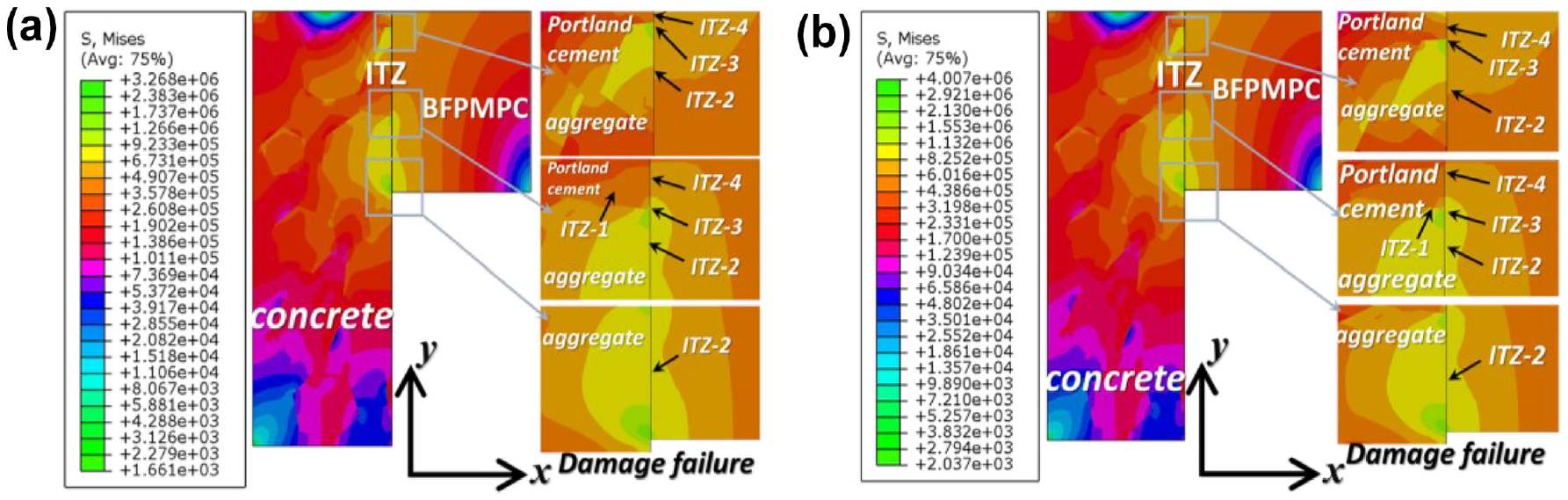
Numerical simulation results: (a) stress nephogram for basalt fiber reinforced and polymer modified magnesium phosphate cement-Portland cement concrete (BFPMPC-PCC)-6 h and (b) stress nephogram for BFPMPC-PCC-3 days.
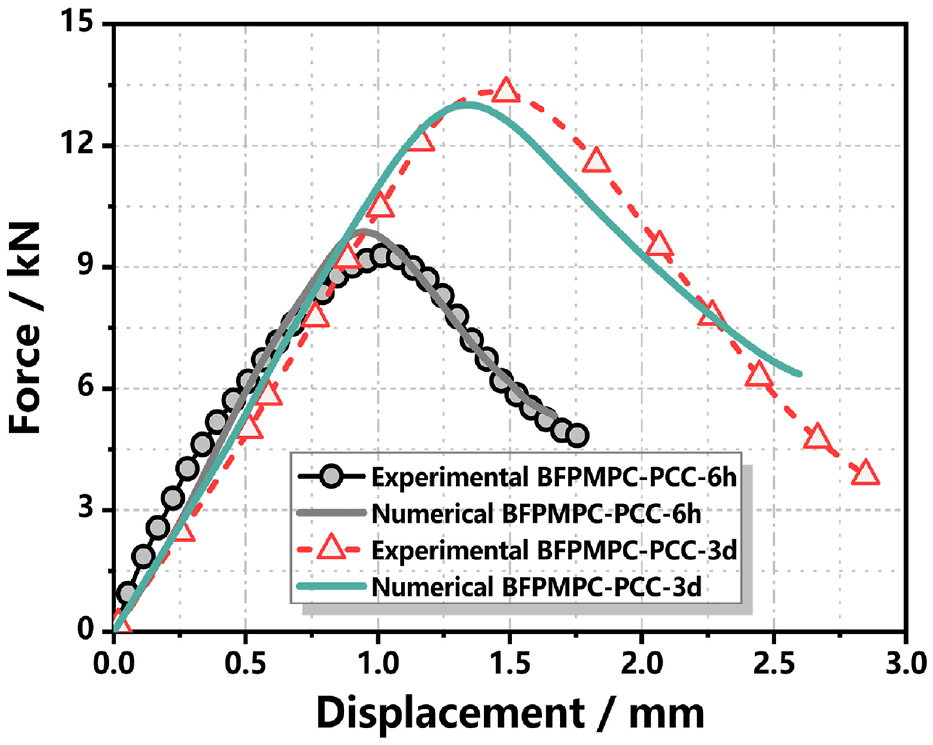
Experimental and numerical load-displacement results both 6 h and 3 days.
Figure 14 shows the microstructure SEM images of ITZs in the repair interface. In Figure 14a, for BFPMPC-PCC-6 h, the outline of ITZs were clearly visible. It was worth noting that the hydration products were loose and not condensed into nuclei within ITZ-3 with large defects. Meanwhile, the situation was different between ITZ-2 and ITZ-4. The coarse aggregate is dense, usually with few components, such as CaO, SiO2. The cement mortar was dominated by various forms of silica-aluminum-calcium compounds with high heterogenicity. Therefore, the BFPMPC paste bond to the coarse aggregate was better than that to the OPC paste with multiple defects. The same situation occurred in the repair interface for BFPMPC-PCC-3 days in Figure 14b.
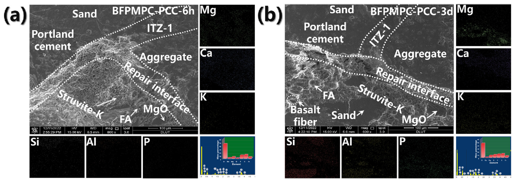
Scanning electron microscopy/energy-dispersive spectrometry (SEM/EDS) analysis for basalt fiber reinforced and polymer modified magnesium phosphate cement-Portland cement concrete (BFPMPC-PCC) interface: (a) 6 h and (b) 3 d.
In summary, the plain shear strength can be effective described by the proposed interface fracture model. However, in practical application, the formula of classical mechanics is a common method to calculate the strength, as shown in Equations 31 and 32 ( 14 , 72 ).


where
Therefore, the analytical, equational and numerical results of interfacial shear strength were compared and summarized as follows, as shown in Figure 15. The minor errors between experimental and numerical of interfacial shear strength were described. In Figure 15, the results of the proposed interface fracture model were more accurate than the formulation. However, a prospect described in this paper was different from the traditional calculation formula. Through a more comprehensive mechanism analysis, the interface shear failure was analyzed and described by a more comprehensive scientific means based on dislocation theory.
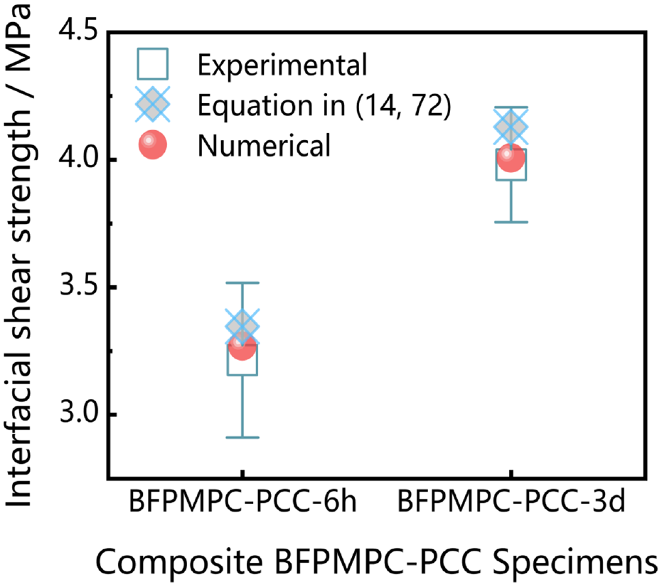
Experimental, equational, and numerical interfacial shear strength of basalt fiber reinforced and polymer modified magnesium phosphate cement-Portland cement concrete (BFPMPC-PCC).
Conclusions and Recommendations
In this paper, an aspect of profound significance for the ITZ was clarified. Creep characteristics on interface between BFPMPC and PCC were studied and verified, then were characterized, with a novel insight, by the combination of modified and generalized Kelvin model and fractional rheological model, resulting in the modified interface fracture model being proposed. The following conclusions are drawn:
For the interface of BFPMPC-PCC, there are three kinds of sub-ITZs in it. Meanwhile, the relationship of elastic modulus of 6 h and 3 days are ITZ-2>ITZ-4>ITZ-3 and ITZ-4>ITZ-2>ITZ-3, respectively. The elastic modulus of interface for basalt fiber was also increased by curing age and was notably closer to the elastic modulus of basalt fiber at 3 days curing age.
SEM and nanoindentation revealed the complex situation in the repair interface. For the large difference between the relatively dense coarse aggregate and the heterogeneous OPC paste, the different bonding effects between them and the BFMPC paste coated by polymer are reflected. The elastic modulus relationship of those two interfaces is ITZ-4>ITZ-2 at 3 days.
The proposed modified and generalized Kelvin model can accurately describe the creep and fractional rheological properties of the repair interface. The fitting model was used to validate the properties of ITZ with a high-fitting degree.
The creep characteristics of the BFPMPC-PCC interface were described well by the modified and generalized Kelvin model. The nanoindentation process of the interface was well simulated by the modified and generalized Kelvin model used in the numerical simulation.
The proposed interface fracture model based on a combination of interface creep characteristics and dislocation theory was validated by experimental and FEM-shear strength test results with high agreements and minor errors.
Compared with the formula calculation results, it is proved that the interface fracture model can describe the BFPMPC-PCC interface fracture behavior well, as polymer existed.
In future, two issues and prospects will continue to be pursued. Firstly, fatigue damage accumulation from repeated traffic loading cycles is the dominant factor affecting the performance and durability of BFPMPC-PCC ITZ as a repair material under traffic-induced stresses. The interface damage caused by fatigue will need to be studied further. Secondly, the complex bonding effects of the interface will be further explored by more advanced chemical analytical instruments, aiming to provide a theoretical basis for the application of BFPMPC to rapid repair and reinforcement of cement and concrete infrastructure, and to guide material design.
Footnotes
Appendix: Analytic interfacial fracture model for BFPMPC and PCC
ITZ, repaired interface between BFPMPC and PCC, is carefully distinguished. According to the previous study ( 15 , 71 ), for the fracture degradation in the repaired interface, the interface is damaged. The process of interface fracture is well described by the four-stage model in pure shear experiments. The first is the perfectly bonded stage, which has the best performance to bear the damage caused by accumulated external forces on the interface. The second stage is partial peeling with the bonding strength increasing slowly and reaching its peak. As the maximum bearing capacity of the interface bond is reached, the interface fracture failure occurs until the interface friction slips. It indicates that the cracks in the interface have a strong ability to expand, and it is realized that the shear behavior is needed to be described by a more effective constitutive law. It can be inferred from the interface fracture in experiments that cement concrete has strong adhesion with strong chemical bond occlusion and van der Waals force adhesion. Therefore, the typical mode II fracture ( 73 ) in the ITZ is presented in the process of the interface shear experiment. Notably, it is necessary to determine the strength of cracks located in the interface sandwich plate under the pure shear load.
As can be seen from Figure A.1, the sandwich structure is presented with an ITZ in between the PCC and BFPMPC. Based on the principle of elastic superposition, the complex pure shear action is decomposed into (1) Both sides are uniform plates with elastic properties, and cracks exist in the middle; (2) The ITZ between PCC and BFPMPC is regarded as a bonding sandwich with shear modulus constant, and interface dislocation ( 74 , 75 ) fracture occurs.
Author Contributions
The authors confirm contribution to the paper as follows: study conception and design: Fei Liu; data collection: Fei Liu; analysis and interpretation of results: Fei Liu; supervision and investigation: Baofeng Pan, ChangjunZhou; draft manuscript preparation: Fei Liu, Baofeng Pan, ChangjunZhou and Baomin Wang. All authors reviewed the results and approved the final version of the manuscript.
Declaration of Conflicting Interests
The author(s) declared no potential conflicts of interest with respect to the research, authorship, and/or publication of this article.
Funding
The author(s) disclosed receipt of the following financial support for the research, authorship, and/or publication of this article: The authors are grateful for the financial support received by the Fundamental Research Funds for the Central Universities (DUT20JC50 and DUT17RC (3)006), the National Natural Science Foundation of China (Grant No. 51508137), the Scholarship from the China Scholarship Council and the Scholarship of Dalian University of Technology.
Data Accessibility Statement
All data, models, or code that support the findings of this study are available from the corresponding author on reasonable request.