
Abstract
This paper investigates the influence of geocell reinforcement on the load carrying mechanism of embankments over soft soil. Using a geocell mattress beneath an embankment on soft soil, the size of the rupture zone in the foundation bed is found to have increased significantly, leading to increase in the mobilized shear resistance, and giving rise to enhanced bearing capacity. While the unreinforced embankment, owing to differential settlements, tends to crack and disintegrate, the geocell reinforced embankment continues to behave as a monolith up to a high surcharge pressure/fill height. The performance improvement tends to increase with increase in height of the geocell mattress. Strain variation in the geocell mattress indicates that its reinforcing efficacy is the largest at the central crest region of the embankment and decreases toward the toe. As the geocell mattress behaves as a semirigid slab, when it is present, the stress dispersion angle tends to increase significantly. Considering the stress dispersion zone as an equivalent rigid footing, the bearing capacity of unreinforced and geocell reinforced embankments are analyzed. The predicted bearing capacities are found to be in close agreement with the experimentally observed ones. Three-dimensional numerical analyses indicate that the pressure–settlement behavior of the embankments observed in the model tests is reproduced at large scale.
Keywords
Earth embankments are widely used in the construction of transportation networks such as railways, highways, and airport runways; irrigation and flood control structures like dams and dikes; harbor installations such as sea walls and break waters, and so forth. These embankment structures are often built over soft clay deposits, resulting in problems like bearing capacity failure, excessive settlement, and lateral instability ( 1 , 2 ). Among the different mitigation measures, use of geosynthetics has been widely favored in practice, primarily for its cost effectiveness and ease of construction. Several studies have been reported, highlighting the beneficial effects of using planar geotextiles and geogrids in the construction of embankments over weak soils ( 3 – 10 ).
A more recent development in this avenue is to use three-dimensional geocell, which provides all-round confinement to the soil mass leading to improved performance ( 11 ). Cowland and Wong ( 12 ), through field data analysis, have inferred that a geocell mattress at the base of an embankment on soft soil behaves like a semirigid raft. Model tests by Krishnaswamy et al. ( 13 ) indicate that performance improvement of embankments on clay is primarily dependent on the geometry and stiffness of the geocell reinforcement. Similar behavior has also been observed in numerical analyses ( 14 , 15 ). Based on experimental and numerical observations, Zhang et al. ( 16 ), Sitharam and Hegde ( 17 ), and Neto et al. ( 18 ) proposed theoretical models for predicting the bearing capacity of geocell reinforced embankments on weak soils. Review of the literature by the authors indicates that most of the studies reported on geocell reinforced embankments on soft soils have focused on improvement of bearing capacity, however, the associated load carrying mechanisms have not been investigated in detail. Therefore, the authors have studied the load carrying mechanism through the instrumented model tests and three-dimensional numerical analyses presented in this paper.
Experimental Details
A line sketch of a typical test configuration is shown in Figure 1. Because of symmetry, only half of the embankment foundation system was simulated. The crest width, bet, and height, he, of the model embankments were kept constant as 400 mm and 300 mm, respectively. The slope of the embankments was 1:1 and the base width was 700 mm. The geocell mattress was kept embedded within the soil mass, as is the practice to protect it against solar ultraviolet light. The width of the geocell mattress in the model tests, bgc, was kept as 600 mm. Geocells of three different heights, hgc: 80, 160, and 240 mm, which are equivalent to 0.2bet, 0.4bet, and 0.6bet, respectively, were considered. As bet is half of the full crest width, hgc of 0.2bet, 0.4bet and 0.6bet are equivalent to 10%, 20%, and 30% of the full crest width, respectively. A gradually increasing uniform surcharge pressure, p, covering the entire crest of the embankment, was applied through a strain controlled device. This was to simulate the increase in the height of the embankment fill during the construction.
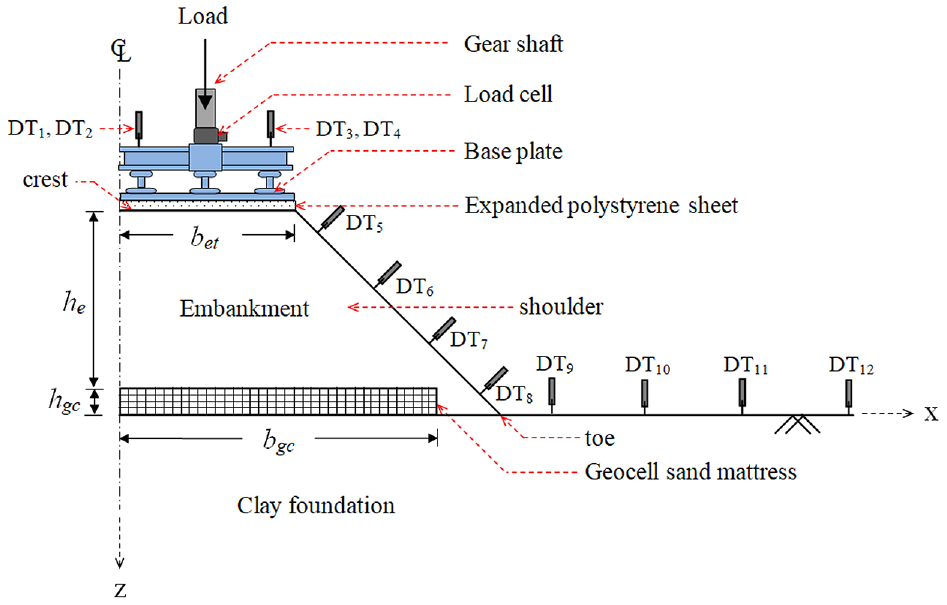
Test geometry.
Foundation beds in the model tests were formed using a locally available soil having 82% fractions passing a No. 200 (75 μm) U.S. standard sieve (Figure 2). The liquid limit, plastic limit, and specific gravity of the foundation soil were found to be 47.3%, 25.6%, and 2.68, respectively ( 19 , 20 ). As per the Unified Soil Classification System ( 21 ), the soil can be classified as clay with low plasticity (CL). The model embankments were constructed using a soil with relatively low fines content (i.e., 20% passing No. 200 sieve). It had effective mean particle size, D10, of 0.09 mm, coefficient of uniformity, Cu, of 3.66, and coefficient of curvature, Cc, of 1.34 (Figure 2). The liquid limit, plastic limit, and specific gravity of the embankment soil were found to be 21%, 11%, and 2.69, respectively ( 19 , 20 ). Correspondingly, the embankment soil was classified as clayey sand, SC ( 21 ). Its optimum moisture content and maximum dry density, obtained through modified compaction tests ( 22 ), were 7.5% and 21.4 kN/m3, respectively (Figure 3).
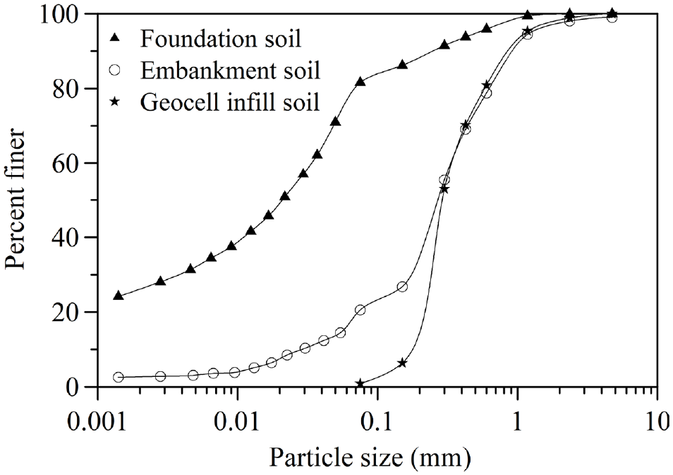
Particle size distribution of soils.
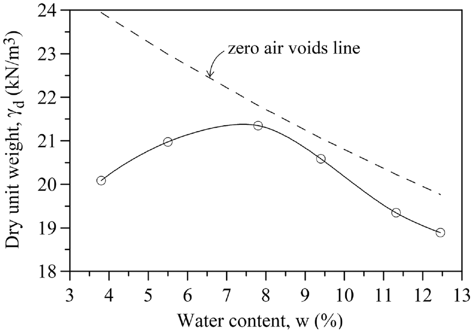
Compaction response of the embankment soil.
The geocells were formed using a biaxial geogrid having aperture size 35 × 35 mm, ultimate tensile strength 19.8 kN/m, and 5% strain secant modulus of 251 kN/m ( 23 ). The geogrid strips, cut into the desired length and height, were arranged in a chevron pattern ( 24 ) with joints at the intersections ( 11 ). The joints were formed by pulling the ribs of the diagonal geogrid up through the transverse geogrid and slipping a bodkin through the loop formed. The bodkins used were 6 mm wide, and 3 mm thick plastic strips, made of low density polypropylene. The strength of the geocell joints obtained through tensile tests was 3.4 kN/m ( 25 ). Such weak joints scaled down the overall strength of the geocell reinforcement, making it suitable for the model tests. The soil used for filling up the geocells was a poorly graded sand with negligible fines content (i.e., 0.88% passing No. 200 sieve). It had D10 of 0.18 mm, Cu of 1.83, and Cc of 0.89. Its friction angle (ϕ) corresponding to 70% relative density (i.e., placement density), obtained through triaxial compression tests ( 26 ), was 39°.
The model tests were conducted in a test setup as shown in Figure 4. The test sections, comprising of the clay foundation and embankment, were formed in a rigid steel tank having internal dimensions: 1,800 mm long, 500 mm wide, and 1,200 mm deep. For observation of the failure patterns, one side of the test tank was fitted with a 25 mm thick transparent perspex sheet. Frictional resistance on the side walls was minimized through provision of a double layered plastic sheet with a coat of silicon grease within.
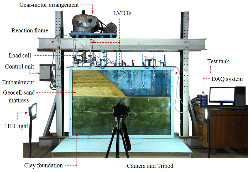
Test setup.
The foundation beds were formed using the clay soil at relatively low consistency. Initially, a series of pilot tests was conducted and a calibration curve correlating the water content, bulk density, and shear strength of the clay soil was developed (Figure 5). Correspondingly, to achieve an undrained shear strength of 10 kPa, the target bulk density of the clay soil was found to be 17.76 kN/m3 and its target water content 39.4%. At this stage the soil was fully saturated (i.e., degree of saturation 100%). Accordingly, for moisture equilibrium, the foundation soil was mixed with the requisite amount of water and kept in an airtight chamber for about a week.
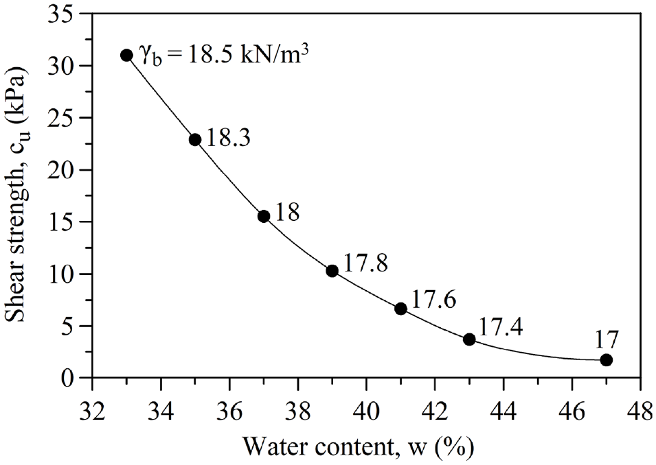
Calibration curve for the foundation soil.
Subsequently, the foundation beds were formed through compaction of the soil, in layers of 50 mm thickness. For each lift, the amount of wet soil required to produce the desired bulk density (i.e., volume of lift × 17.76 kN/m3), was weighed out and placed in the test tank, leveled, and compacted. Compaction was achieved using a wooden board and a flat bottomed tamper with depth markings on the tank side walls as guide. After formation of the foundation bed, the geocell reinforcement was placed on top of it and filled with sand through pluviation, using a sand raining device. Conforming to IRC36 ( 27 ) guidelines, the embankment soil was compacted to 98% maximum dry density condition (i.e., water content: 5.5%, dry density: 21 kN/m3). Accordingly, the soil was mixed with the desired quantity of water and kept in an airtight chamber for moisture equilibrium. It was then compacted in layers of 50 mm thickness, as discussed earlier. For ease of construction, the soil was compacted in cuboid shape through support systems, and then trimmed off to form the embankment. Details of the construction steps are depicted in Figure 6. After formation of the foundation bed (step 1), the geocell reinforcement was placed on it (step 2). Following that, wooden plank supports 1 and 2 were positioned next to the geocell reinforcement and toe of the embankment, respectively. Then, the embankment soil was packed between the two supports and compacted (step 3). Subsequently, support 1 was removed and the geocells were filled with sand (step 4). Next, the embankment soil was compacted in layers (step 5). On reaching the crest level, support 2 was removed and the cuboid-shaped soil mass was trimmed off at a 1:1 slope, with marking on the tank side wall as guide, leading to formation of the embankment (step 6). During construction, undisturbed soil samples were collected from different locations in the foundation bed, sand fill, and embankment. The sand samples were collected by aluminum cans of size: 40 mm in diameter and height. Soil samples from the foundation bed and embankment were collected by thin walled cylindrical samplers of size: 38 mm internal diameter and 80 mm height. The placement density and moisture content of the soils corresponding to different locations in the test section were found to be close to the target values, with coefficient of variability in the range of 1.5%.
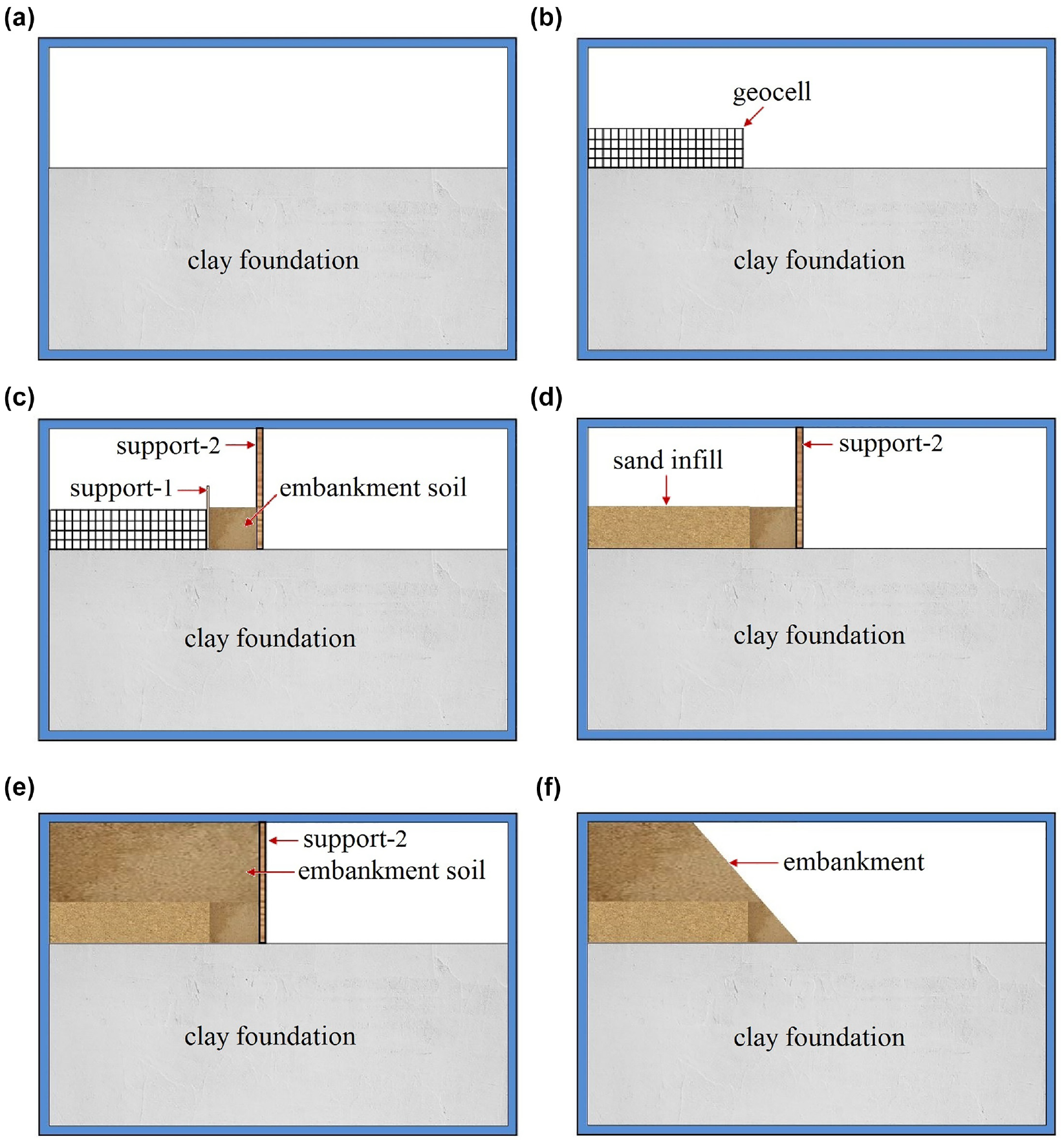
Steps for construction of the foundation bed and embankment: (a) step 1, (b) step 2, (c) step 3, (d) step 4, (e) step 5, and (f) step 6.
Load was applied through a strain controlled motorized gear device, as shown in Figure 4. To create a uniform surcharge pressure, the load from the gear shaft was transmitted to the embankment through a braced steel plate covering the entire crest, with an expanded polystyrene sheet underneath (Figure 1). The loading plate assembly was connected to the gear shaft through a hinge-like arrangement so that it was free to rotate along with the embankment. The load was applied in strain controlled manner, at a rate of 2 mm/min. A relatively faster rate of loading was intended to simulate nearly undrained response in the clay foundation, leading to zero friction angle. Loads transferred to the embankment were recorded through an electronic load cell of compression type, with 500 kN measuring capacity. The resulting settlement of the embankment was measured through linearly variable differential transducers (LVDT), placed at four corners of its crest (DT1, DT2, DT3, DT4 in Figure 1). They were of inductive type, with measuring range 0 to 100 mm. Settlement, s, of the embankment, as reported here, is the average of the readings from these four LVDTs. Deformations of the embankment slope were measured at four locations corresponding to heights, z/he, of 0.16, 0.5, 0.83, and 1.16 (for the unreinforced case, the first three only). At these locations the LVDTs (DT5, DT6, DT7, DT8) were placed perpendicular to the slope surface. The corresponding vertical and horizontal displacements were obtained by resolving the readings in the x and z directions, respectively. Vertical deformations, δv, on the foundation surface were measured at distances, x, of 2bet, 2.5bet, 3bet, and 4.3bet, from the center of the embankment, through the LVDTs: DT9, DT10, DT11, and DT12, respectively. The measuring range of these inductive displacement sensors (i.e., DT5–DT12) was 0 to 50 mm. Strains developed in the geocell reinforcement were recorded through a series of electrical-resistance type strain gauges of 5 mm gauge length, 120 ohm resistance, and 2.1 gauge factor. The strain gauges were mounted on the geocell reinforcement, along its width, at mid height (Figure 7). At each location, the geocell surface was wiped clean with a neutralizing solution and a cloth. Next, the strain gauge was pasted to it with a quick setting adhesive. Electrical connecting wires were soldered with the strain gauge leads over a copper bridge fixed onto the geocell wall by adhesive. Subsequently, the strain gauge along with the soldered region was covered with a protective layer of cello tape. All the sensors were connected to an automated data acquisition system. It had 32 channels with sampling rate 20 kHz/channel. Data logging was done through the data acquisition software and a computer.
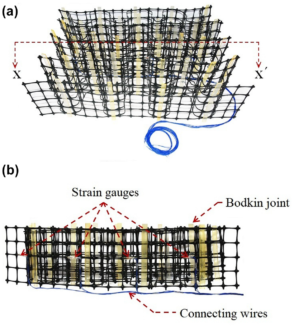
Strain gauges on geocell reinforcement: (a) perspective view and (b) sectional view.
Patterns of deformation in the embankment and foundation soils were analyzed using the particle image velocimetry (PIV) technique, based on velocity measurements ( 28 ). Continuous images of the soil planes were taken through the transparent wall of the test tank using a digital camera with proper lighting arrangements, as shown in Figure 4. The images, captured at intervals of 10 s, had a resolution of 4,800 × 3,200 pixels. The soil surface, flush with the transparent wall of the tank, was smeared with colored flock to enhance the surface texture and contrast necessary for the image analysis. Artificial flock was also applied to the embankment and geocell-sand mattress surface. Additionally, control points with known object-space coordinates were marked on the outer side of the transparent window. The images were analyzed using the GeoPIV-RG program ( 29 ). The control points were used to calibrate the image-space coordinates to the object-space coordinates, using the subroutine available in GeoPIV-RG. Deformations of the soil particles were estimated by tracking the spatial variation in brightness, between the successive images, captured through the camera. For this, the initial image was divided into a mesh of test patches. Correlation between these test patches and the search patches from the following image were analyzed to obtain the displacement trajectories of each test patch between the two successive images. This process was repeated for the entire set of images in the series, and the soil displacement field was obtained.
Rochelle et al. ( 30 ), from failure of a full-scale embankment on soft clay, observed that the failure zone had extended over a distance of about half the crest width of the embankment, beyond the toe. In the present tests, distance of the tank side wall from the toe of the half-embankment was more than two and half times the crest width. Moreover, pressure transmitted to the tank bottom and side wall in the rupture direction, measured through earth pressure cells, was less than 2% of the applied surcharge pressure. Therefore, it can be said that the tank boundary effects on the test data were practically negligible.
Results and Discussion
Pressure–Settlement Behavior
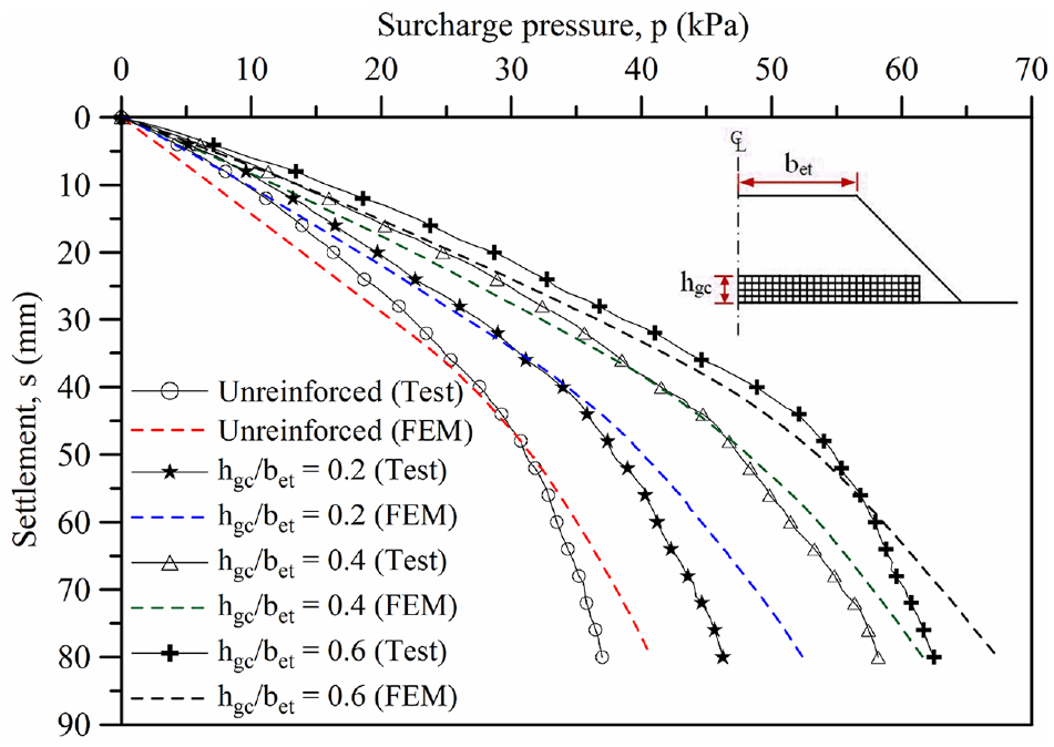
The surcharge pressure versus settlement response of the embankment, as obtained from the model tests, is presented in Figure 8. Pressure, p, is calculated as the applied load on the embankment divided by its crest area. Settlement, s, is the average of the LVDT readings at the four corners of the embankment crest. In general, the pressure–settlement responses did not show any clear failure. At settlement in the range of about 40 to 45 mm (i.e., 10%–12% of bet), however, the responses tended to be nonlinear, indicating that the soil in the foundation bed had started yielding. Beyond this stage, though, the pressure–settlement responses steepened slightly but remained fairly flat, indicating that the system has continued to support additional loading. This is attributed to localized yielding of the clay foundation, typically referred to as local shear failure ( 31 ). It can be seen that with the geocell-sand mattress at base of the embankment, its load carrying capacity has increased significantly. For example, at settlement of about 40 mm (i.e., 10% of bet), the surcharge pressure in the unreinforced case was 27.5 kPa. As the embankment soil density was 21 kN/m3, the surcharge pressure corresponds to fill height of 1.3 m, leading to total height of the embankment at 1.6 m (i.e., 1.3 m + model height: 0.3 m). However, with the provision of geocell reinforcement having hgc of 0.2bet, 0.4bet, and 0.6bet, the surcharge pressure at a similar settlement (i.e., 40 mm), increased to 34, 41.5, and 49 kPa, respectively. Correspondingly, the equivalent fill heights are 1.9 m, 2.3 m, and 2.6 m, leading to improvements in the order of 19%, 44%, and 63%, respectively. Further, the pressure–settlement response in the reinforced cases was found to be much stiffer than the unreinforced case, indicating that the geocell reinforcement can reduce the embankment settlement substantially. For example, at surcharge pressure of 37 kPa, while the unreinforced embankment settled by 80 mm, in the reinforced cases with hgc/bet of 0.2, 0.4, and 0.6, settlement was 47 mm, 34 mm, and 28 mm, respectively. Correspondingly, the settlement reductions were in the order of 41%, 57%, and 65%, respectively. These results are further analyzed using other measured data, as detailed below.
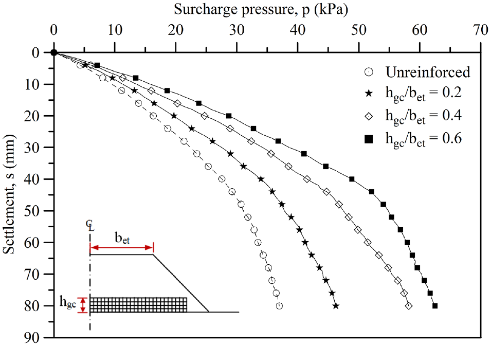
Surcharge pressure versus settlement responses.
Surface Deformation
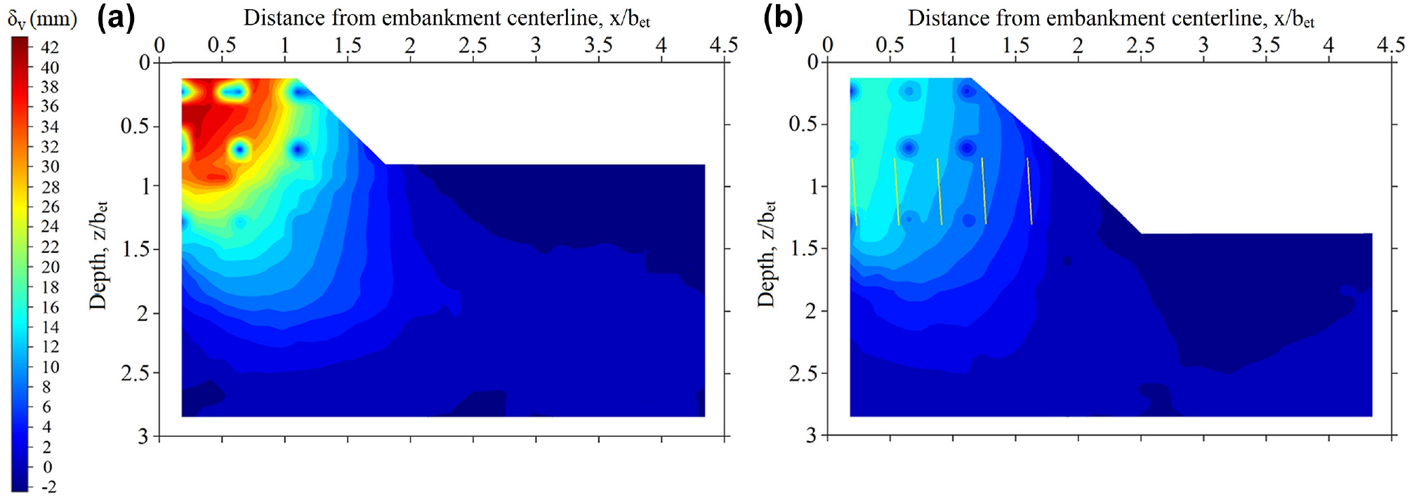
Typical vertical deformation (δv) profiles measured on the embankment and foundation surface are shown in Figure 9. The downward deformations (i.e., settlement) are shown as positive and the upward deformations (i.e., heave) as negative.
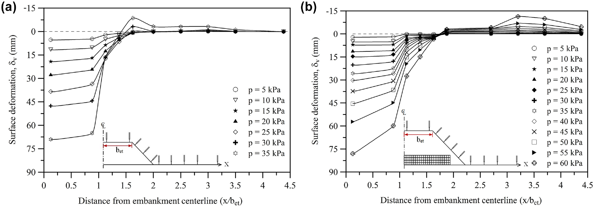
Surface deformation profiles: (a) unreinforced and (b) geocell reinforced (hgc/bet = 0.6).
The responses of the unreinforced embankment, depicted in Figure 9a, indicate that the crest settled more than the shoulder, and the differential settlement continued to increase with increase in the surcharge pressure. Relatively less settlement in the shoulder region of the embankment is attributed to two reasons. First, the reduced intensity of stress owing to dispersion of the surcharge pressure led to reduced strain in the soil mass. Second, as will be discussed below, the shoulder portion tends to become separated from the crest portion with visible vertical cracking. Therefore, it can be said that the contribution of the shoulder of the embankment in sustaining the surcharge loading is significantly less in that it mostly acts as an overburden against yielding of the foundation soil. It can be seen that the crest of the unreinforced embankment has settled nonuniformly, with increasingly greater settlement toward its center (Figure 9a), which indicates that the embankment under loading has tended to rotate. Such rotational deformation in the unreinforced embankment was apparent even when the surcharge pressure was as low as 5 kPa (equivalent fill height: 0.54 m). Beyond a surcharge pressure of about 30 kPa, which corresponds to fill height of 1.73 m, settlement and rotation of the embankment increased significantly. Moreover, visible heaving was observed in the region close to the toe of the embankment, which indicates that rupture in the foundation bed was very much localized. Similar observations, in a prototype embankment on soft soil, have been reported by Rochelle et al. ( 30 ). Therefore, it can be said that the general mechanism and failure behavior observed in the model tests are reproducible at large scale.
With geocell reinforcement, deformations on the embankment and foundation surface were reduced significantly (Figure 9b). For example, at surcharge pressure of 35 kPa, maximum settlement on the embankment crest, which was around 70 mm in the unreinforced case, decreased to less than 25 mm in the geocell reinforced case. Moreover, the crest of the reinforced embankment continued to settle uniformly up to surcharge pressure as high as 25 kPa (equivalent fill height: 1.5 m). In parallel, the shoulder portion, without exhibiting any visible settlement, remained stable up to surcharge pressure of about 15 kPa; beyond that, it settled uniformly up to surcharge pressure of about 25 kPa. Correspondingly, differential settlements between the shoulder and crest of the embankment decreased significantly. For example, at 30 kPa surcharge pressure, which corresponds to equivalent fill height of 1.73 m, differential settlement between the crest and shoulder of the embankment, which in the unreinforced case was around 32 mm, decreased to less than 12 mm with geocell reinforcement. This establishes that the geocell reinforcement has tended to act as an anchorage to the embankment crest (i.e., the portion of the embankment directly under the loading) against settlement, which is attributed to mobilization of passive resistance from the surrounding soil. However, beyond that (i.e., p greater than 30 kPa), settlement gradually increased toward the center of the embankment (CL, Figure 9b), with impending rotational failure. At this stage, heaving on the foundation bed tends to be visible, which indicates that the shearing zone in the foundation bed had reached the ground surface. However, the magnitude of heaving decreased significantly. For example, at 35 kPa surcharge pressure, peak heaving in the unreinforced case was about 7.5 mm, but with geocell reinforcement it was practically negligible. In fact, at surcharge pressure as high as 55 kPa (equivalent fill height: 2.92 m), heave on the foundation surface was less than 5 mm. This observation establishes that the geocell mattress helped in dispersing the embankment loading over a wider area, leading to reduced stress in the foundation bed giving rise to reduced heaving. Furthermore, with geocell reinforcement, the peak heaving zone shifted by a distance of about 1.5bet away from the toe of the embankment, which indicates that the rupture zone in the foundation bed had widened significantly. Consequently, increased shear resistance was mobilized, leading to enhanced bearing capacity and, accordingly, increased height of the embankment fill. These performance improvements are attributed to the three-dimensional confinement and rigidity effect of the geocell reinforcement that enabled the encapsulated soil mass to behave as a stiffened mat and thereby effectively supported the embankment against surcharge loading.
Typical lateral deformation profiles of the embankment slope are presented in Figure 10. These measurements were obtained through the displacement transducers DT5–DT8, as shown in Figure 1. The corresponding vertical and horizontal coordinates (u,v) are plotted, considering the initial position of the crest edge (0,0) as the reference. Directions of the lateral movements and rotation of the slope are shown through arrow marks. It can be seen that, in the unreinforced case, the embankment has rotated at about its mid height. As the foundation soil underneath the embankment crest tends to yield, the fill soil tends to cave in leading to an inward movement. The associated heaving in the foundation bed tends to move the toe of the embankment in the outward direction, leading to rotational failure. In the reinforced case, however, the entire slope has rotated inwards and the point of rotation has moved down, close to the top edge of the geocell mattress (Figure 10b). This may be because the geocell mattress, with its rigidity, tends to bridge over the yielding foundation bed leading to reduced distortions in the embankment. Consequently, the embankment has behaved as a monolith. Little outward movement was observed close to the toe (Figure 10b), indicating that the geocell layer has rotated along with the embankment. Therefore, it can be said that the geocell-sand mattress tends to behave like a semirigid slab that restrains the embankment against potential failure, leading to increased load carrying capacity of the system.
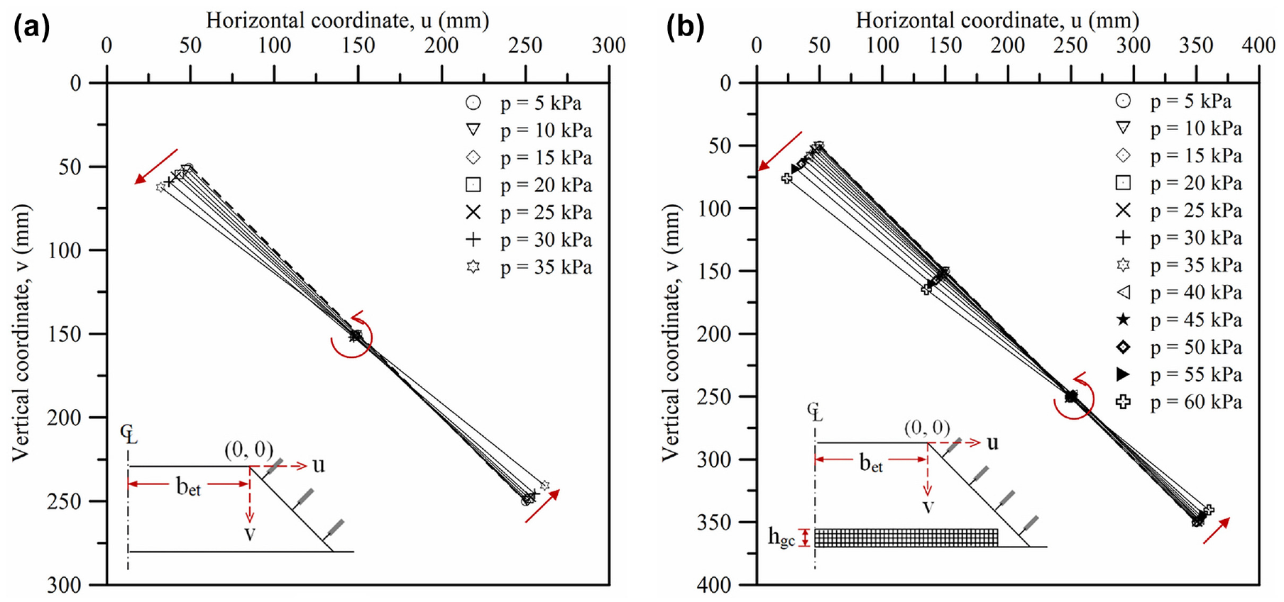
Lateral deformation patterns of the embankment slope: (a) unreinforced and (b) geocell reinforced (hgc/bet = 0.6).
From Figure 10, it can also be seen that initially the lateral deformation profiles of the embankment slope, corresponding to different surcharge pressures, are very close to each other and are almost proportional. With geocell reinforcement, the responses are nearly superimposed over each other. This observation establishes the elastic response of the system in the initial stages of loading which tends to be more prominent with the geocell reinforcement. However, beyond surcharge pressure of about 25 kPa in the unreinforced case and 40 kPa in the geocell reinforced case, the lateral deformations are found to be disproportionately increasing, exhibiting nonlinear behavior which indicates that the system has tended to fail. This is in agreement with the pressure–settlement responses of the embankments as depicted in Figure 8.
Crack Formation in the Embankment
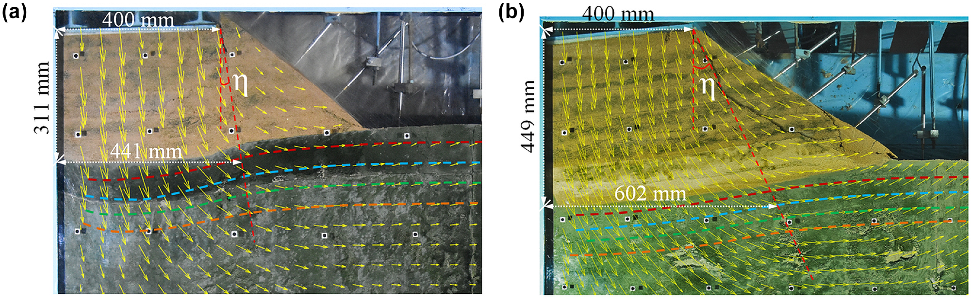
Post test photographic view and the corresponding line sketches depicting typical cracking and deformation patterns of the unreinforced and geocell reinforced embankments are shown in Figure 11. The original cross section is included for the purpose of comparison. It can be seen that, in the unreinforced case (Figure 11a), the embankment has undergone visible differential settlement between its crest and shoulder. Besides, significant structural cracks have developed in the vertical and diagonal directions. Initially, at about 20 kPa surcharge pressure (equivalent fill height: 1.25 m), vertical cracks started forming from the top of the embankment and propagated downward. The vertical crack at the crest–shoulder junction was relatively prominent and extended onto the foundation bed which indicates that they had tended to separate, leading to the differential settlement observed. At surcharge pressure of about 30 kPa (equivalent fill height: 1.72 m), a diagonal crack started forming at some depth below the crest and propagated toward the foundation bed. Subsequently, the embankment fill started shearing and punching onto the foundation bed associated with visible heaving close to the toe. This establishes the proposition stated above, that the embankment crest tends to cave in, onto the yielding foundation bed, leading to differential settlements. In contrast, the geocell reinforced embankment exhibited a gradually increasing settlement toward its center (Figure 11b). Besides, fissures were limited to the slope surface only; there were no visible structural cracks in the embankment body even at surcharge pressure as high as 60 kPa (equivalent fill height: 3.15 m). With increase in height of the geocell mattress, cracks formed in the shoulder were mostly restricted to the outer surface of the slope (Figure 11c). Therefore, it can be said that, while the unreinforced embankment on soft clay tends to disintegrate because of differential settlement, with geocell reinforcement it continues to behave as a monolith up to a large surcharge pressure/fill height.
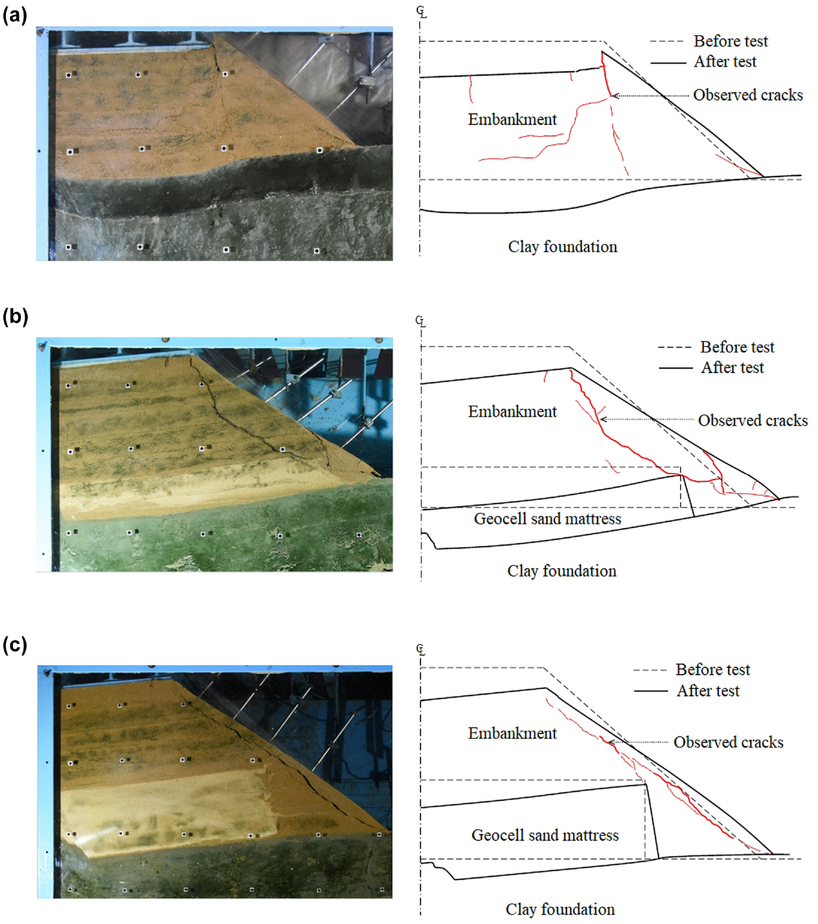
Cracking and deformation patterns of the embankment: (a) unreinforced, (b) geocell reinforced (hgc/bet = 0.2), and (c) geocell reinforced (hgc/bet = 0.6).
It is of interest to note that, while crack formation in the unreinforced case was initiated from the top of the embankment, in the reinforced case, it started developing from the outer top edge of the geocell mattress, that is, adjacent to the sloped surface. As the geocell mattress tends to share the embankment load effectively, stress concentration develops at its outer edge because of discontinuity leading to the crack formation. From these observations it can be said that, in the unreinforced case, the crest of the embankment tends to be punched down onto the clay foundation indicating bearing capacity failure. As the geocell mattress behaves as a wide slab, it restrains the embankment against punching onto the foundation bed and thereby inhibits differential settlement, leading to improved performance of the system. Such wide slab behavior has also been observed by Dash and Choudhary ( 32 ) in the case of geocell reinforced anchors.
The other major reason for crack formation in the embankment is attributed to the lateral thrust from horizontal stresses induced in the soil fill ( 33 ). Consequently, tensile stresses are developed, leading to cracking ( 34 ). With its relatively high tensile strength and visibly rough interface, created by its pocket openings, the geocell mattress restrains the embankment fill against lateral sliding and shares the resulting stresses effectively. Consequently, the fill soil remains stable up to a high surcharge pressure, which opens up possibilities of constructing embankments of relatively greater height over soft soil. Minor fissures that developed close to the sloped surface are attributed to the localized stress concentration effects, as discussed earlier.
Strain in Geocell Reinforcement
Strain variations in the geocell reinforcement, along the width of the embankment, corresponding to relatively shallow and deep height geocell mattresses (i.e., hgc: 0.2bet, 0.6bet), are shown in Figure 12, a and b , respectively. In general, strains in the reinforcement are found to be tensile (+) in nature, which establishes that the geocell mattress has effectively restrained the embankment fill and the foundation soil against lateral sliding. The maximum strain was observed at the center of the embankment and it decreased toward the toe. Increased lateral thrust and deformation in the fill soil, gradually toward the center of the embankment, develops increased stress transfer to the geocell mattress leading to increase in strain. Therefore, it can be said that the efficacy of the geocell reinforcement in restraining the fill soil against instability is significantly greater in the central crest region of the embankment.
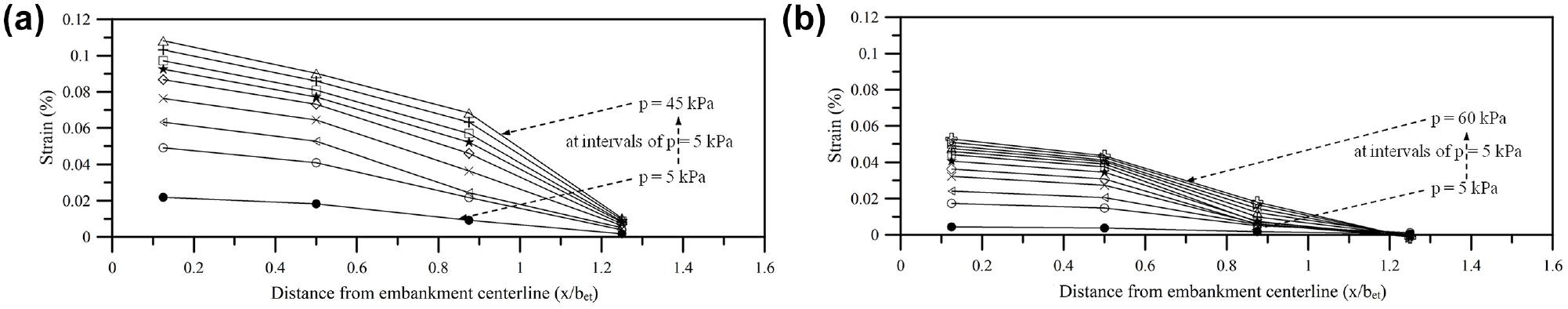
Strain variation in geocell reinforcement: (a) hgc/bet = 0.2 and (b) hgc/bet = 0.6.
Visibly reduced strain toward the shoulder of the embankment suggests that the end portion of the geocell reinforcement has contributed in a secondary manner by deriving anchorage through mobilization of passive resistance from the surrounding soil. With increase in height (hgc), strain in the geocell reinforcement is found to have reduced significantly. For example, at 45 kPa of surcharge pressure, the maximum strain developed in the geocell mattress with hgc of 0.2bet was 0.11%; but in the case of hgc = 0.6bet, it was less than 0.05%. Because of the increased rigidity with increase in height of the geocell mattress, the embankment loading tends to be dispersed over wider area, leading to reduced stress and therefore less strain in the reinforcement.
It is of interest to note that, with increase in surcharge pressure, successive strain increments in the geocell reinforcement tended to decrease. Moreover, beyond surcharge pressure of about 25 kPa with hgc = 0.2bet, and 40 kPa with hgc = 0.6bet, the strain increments are found to have decreased significantly. As discussed earlier, at such high surcharge pressure the embankment tends to crack and deform, and thereby its ability to transmit the surcharge loading onto the geocell mattress tends to be reduced. Consequently, relatively less stress is transferred to the geocell reinforcement leading to reduced strain in it. Therefore, it can be said that the efficacy of the geocell reinforcement is also dependent on the stability of the fill soil and that for better performance improvement the embankment should be made of relatively stronger soil.
Vertical Displacement Contour
Typical contours of vertical deformations (δv) for unreinforced and geocell reinforced cases are presented in Figure 13, a and b , respectively. These data were obtained from the PIV analysis. A line sketch of the deformed geocell mattress is included for clarity. The downward displacement (+) depicts settlement and upward displacement (–) heave. Localized dark spots seen in these figures are the fixed reference points marked on the test tank wall, as mentioned earlier. Both the contours were computed at surcharge pressure of 29 kPa. This corresponds to failure in the unreinforced case, and was obtained from the pressure–settlement response through the tangent intersection method ( 35 ). In general, vertical displacement of the soil particles was found to be the maximum in the crest region of the embankment, which is attributed to the stress concentration effects. This is in agreement with the observation that vertical cracks formed in the soil fill were initiated from the embankment top.
Vertical displacement contours (surcharge pressure, p: 29 kPa): (a) unreinforced and (b) geocell reinforced (hgc/bet = 0.6).
With provision of geocell reinforcement, vertical deformations in both the embankment and foundation bed decreased significantly (Figure 13b). For example, the peak vertical displacement in the embankment fill, which was around 43 mm in the unreinforced case, was reduced to 18 mm with the geocell reinforcement, a reduction in the order of 58%. Because of its shear and bending rigidity, the geocell reinforcement effectively supports the embankment against the surcharge loading, leading to reduced vertical deformation in the soil fill. Similar trends were also observed in the foundation bed. For example, peak vertical displacement in the foundation soil, which was around 36 mm in the unreinforced case, with geocell reinforcement decreased to less than 10 mm, a reduction in the order of 72%. Because of its slab like behavior, the geocell mattress helps to redistribute the surcharge loading over a wider area, onto the foundation bed. Consequently, induced stresses in the foundation bed tend to decrease, leading to reduced settlement. This is in agreement with the pressure–settlement behavior of the system, as discussed earlier.
Horizontal Displacement Contour
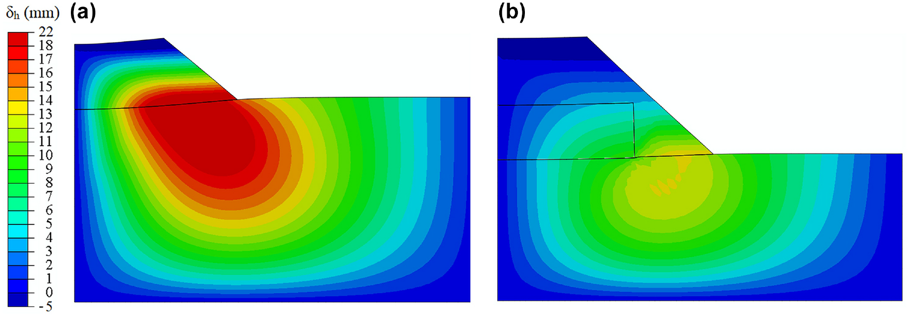
Typical variation of horizontal displacement (δh), in the unreinforced and geocell reinforced cases, is depicted in Figure 14, a and b , respectively. Both these contours were obtained through image analysis corresponding to surcharge pressure of 29 kPa (i.e., the ultimate capacity of the unreinforced embankment). It can be seen that the lateral deformations are significantly larger in the toe region, close to the foundation bed. This is attributed to the stress concentration effects caused by change in geometry and lack of confinement resulting from the free boundary. It also indicates that the soil initially tends to yield near the toe of the embankment and the plasticity zone gradually spreads inward.
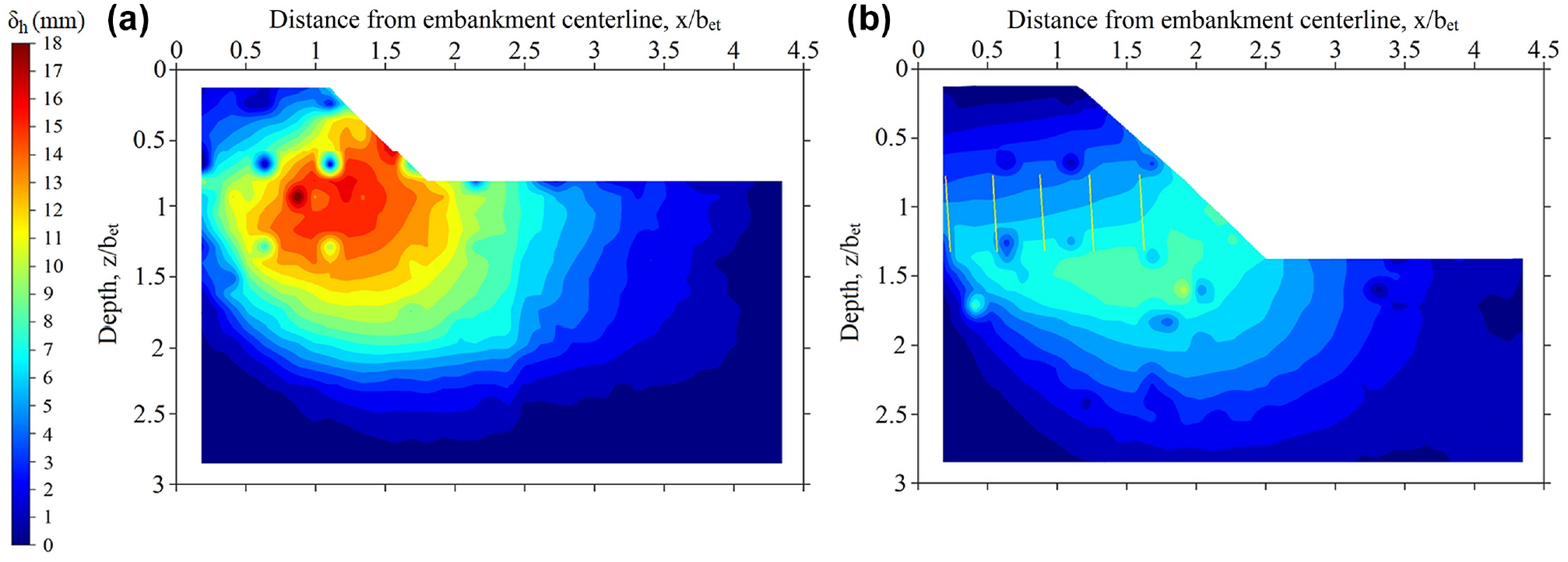
Horizontal displacement contours (surcharge pressure, p: 29 kPa): (a) unreinforced and (b) geocell reinforced (hgc/bet = 0.6).
With geocell reinforcement, the horizontal displacement decreased significantly. For example, peak lateral displacement in the embankment, which was around 17 mm in the unreinforced case, decreased to less than 7 mm in the geocell reinforced case. This is because the protruding walls of the geocell reinforcement along with its granular soil infill tend to restrain the embankment soil against shearing. Moreover, the geocell mattress, because of its rigidity, tends to resist the outward thrust of the embankment fill leading to reduced horizontal displacements. This is in agreement with the tensile strains developed in the geocell reinforcement, as discussed earlier. It once again establishes that provision of geocell mattress can effectively restrain the embankment against lateral spreading.
Moreover, with geocell reinforcement, lateral deformations in the foundation soil too have decreased significantly. The maximum horizontal displacement in the foundation bed decreased from about 18 mm in the unreinforced case to less than 10 mm in the geocell reinforced case, a reduction in the order of 44%. As the relatively stiff geocell walls along with the sand infill tend to punch onto the weak foundation below, a perfectly rough interface is created that effectively restrains the soft soil against lateral extrusion. Moreover, the geocell mattress, because of its rigidity has restrained the embankment against punching down onto the foundation soil. Consequently, stress distribution in the foundation bed tends to be relatively uniform, leading to reduced stress intensity and, accordingly, reduced lateral deformations.
Flow Field
Typical flow field diagrams depicting resultant displacement (δ) vectors and the corresponding contours are shown in Figure 15. These data correspond to crest settlement, s, of 80 mm. In the unreinforced case (Figure 15a), the flow vectors in the central region of the embankment are mostly vertical, which indicates that the embankment crest has punched down onto the clay foundation below. But in the reinforced case (Figure 15b), the flow vectors above the geocell mattress, being relatively outward, exhibit that the fill soil under surcharge loading has tended to move outward. Relatively closely spaced displacement contours depict stress concentration at the center of the embankment, which establishes that the geocell mattress has effectively restrained the fill soil against punching down. Contrary to this, flow vectors in the foundation bed, both in the unreinforced and geocell reinforced cases, depict laterally outward movement indicating rotational failure.
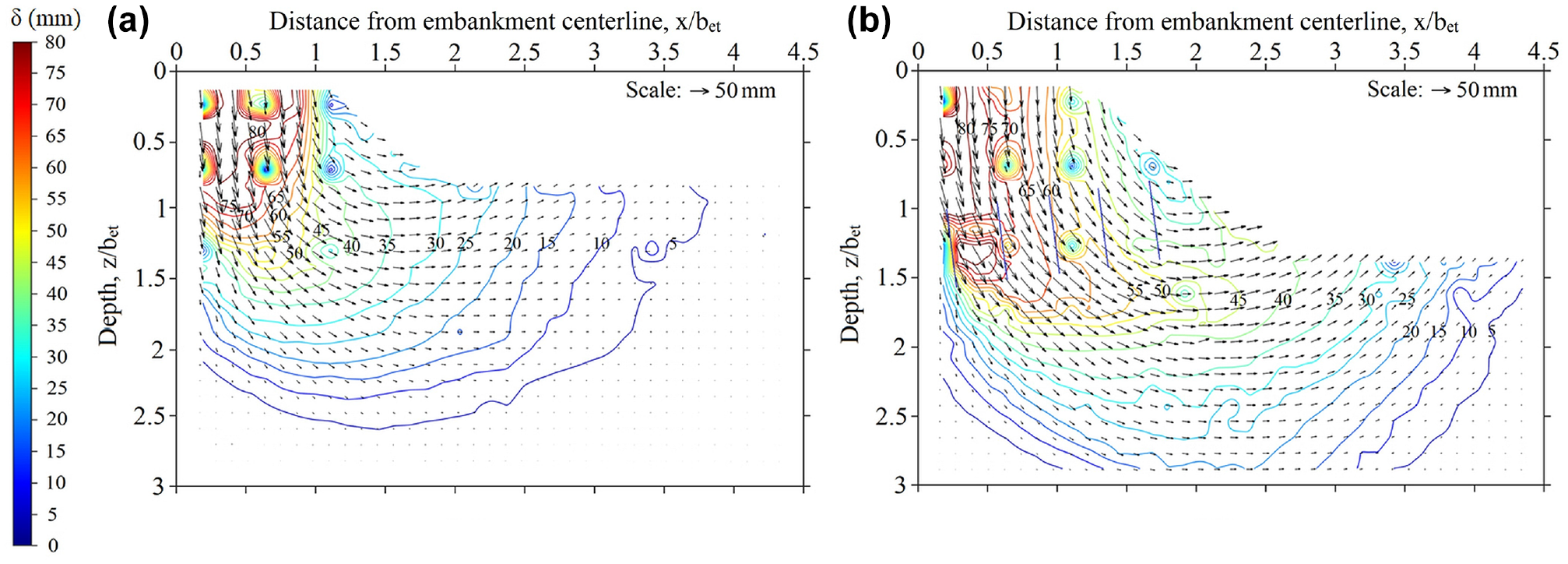
Flow vector-cum-resultant displacement contours (settlement, s: 80 mm): (a) unreinforced and (b) geocell reinforced (hgc/bet = 0.6).
In the unreinforced case (Figure 15a), vertically aligned displacement contours with relatively closer spacing at the crest–shoulder junction, indicate stress concentration. This is in agreement with the vertical crack formation in the unreinforced embankment, as discussed earlier (Figure 11a). In the reinforced case, however, such stress concentrations were not observed (Figure 15b). As differential settlement leads to stress concentration, it is established that with geocell reinforcement the embankment has behaved as a monolith. This is in agreement with the absence of structural cracks in the embankment. However, both in the unreinforced and reinforced cases, the magnitude of displacement in the foundation bed, away from the embankment, decreased gradually. This indicates that stress propagation, and consequent failure in the foundation bed, is relatively progressive. Moreover, with geocell reinforcement, the displacement contours in the foundation bed, as compared with the unreinforced case, are found to have moved vertically downward and laterally outward. This establishes that the geocell mattress has enabled the embankment loading to be dispersed over a wider area onto the foundation soil, leading to improved performance of the system. Considering 5 mm displacement contours as the boundary of the shear zone, it can be seen that the failure surface in the reinforced case is significantly larger than that in the unreinforced case. Consequently, increased resistance is mobilized in the foundation bed, leading to improved performance of the system.
Stress Dispersion
As observed in the model tests, an unreinforced embankment mostly fails through breaking away of its crest and punching onto the soft clay below. In contrast, the geocell reinforced embankment tends to settle as a monolith. Because of its shear and bending rigidity, coupled with tensile resistance, the geocell mattress tends to restrain the embankment fill against structural cracking. It also helps in redistributing the embankment loading over a wider area onto the foundation bed. The load dispersal area was delineated through the displacement vector diagrams of the soil particles, as shown in Figure 16. A line joining the tips of the vectors, corresponding to a particular depth level, depicts the displacement profile of the soil mass. A similar technique was used by Gedela et al. ( 36 ). Typical profiles, shown in Figure 16, indicate that the foundation soil under the crest of the embankment has undergone settlement while in the adjacent region it has tended to heave. The point where the curvature of the displacement profile tends to change indicates the stress dispersion boundary. Joining a series of such inflection points, the line of stress dispersion was delineated. Correspondingly, the stress dispersion angle, η, was obtained through arctan relationship. Accordingly, the load dispersion angle, η, in the unreinforced case was found to be 7.5°, and in the reinforced cases with hgc/bet of 0.2, 0.4, and 0.6, was 24.2°, 31.7°, and 35.8°, respectively.
Delineation of load dispersion angle (a) unreinforced, (b) geocell reinforced (hgc/bet = 0.2).
It can be seen that in the reinforced cases the load dispersion angle has increased significantly, which once again establishes the efficacy of the geocell reinforcement in redistributing the embankment loading over a wider area. With increase in height, rigidity of the geocell mattress tends to increase, leading to reduced deformations in the embankment and giving rise to increase in the load–spread angle. Contrary to this, Dash et al. ( 37 ), in the case of rigid strip footing on geocell reinforced sand foundation beds, observed that beyond a certain height of geocell mattress the stress dispersion angle tends to decrease. This was attributed to local yielding of the geocell mattress from the stress concentration effects under the rigid footing. In the present case, however, the flexible embankment with soft clay foundation allows relatively gradual yielding, leading to ameliorated stress propagation. Consequently, the geocell mattress continues to remain intact up to high surcharge pressure, and thereby exhibits enhanced load dispersion ability.
Analytical Model
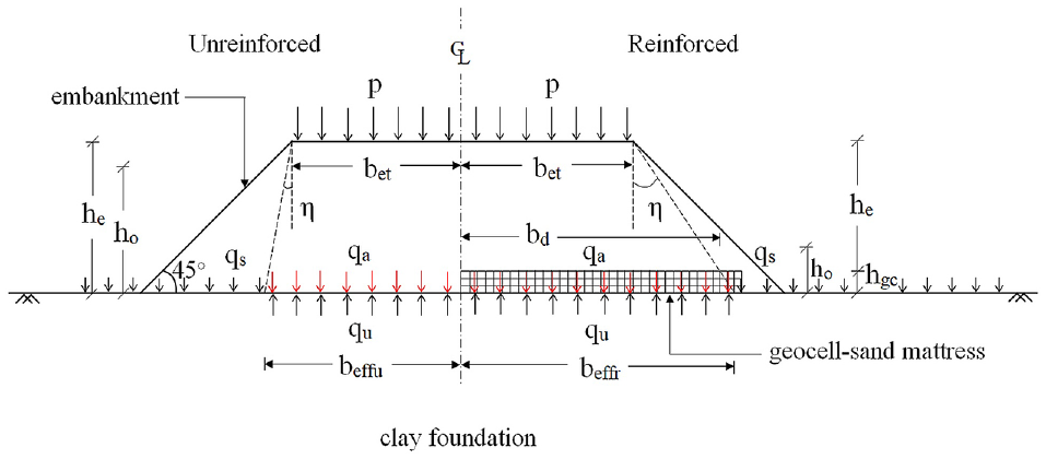
As discussed earlier, in the unreinforced case, the crest portion of the embankment exhibits marginal stress dispersion and tends to punch down onto the soft soil below. But with geocell reinforcement, cracking of the embankment is significantly restrained. Consequently, the stress dispersion tends to be much wider, propagating onto the shoulder of the embankment. Details of these mechanisms are summarized in Figure 17.
Load carrying mechanisms.
The stress dispersion zone of the embankment on the foundation bed is assumed to be an equivalent rigid strip footing ( 38 ). Considering local shear failure, as discussed in the “Pressure–Settlement Behavior” section, the ultimate bearing resistance, qu is estimated as,

Because of the saturated undrained condition, the friction angle of the soil in the foundation bed tends to be zero. Correspondingly, the bearing capacity factors can be taken as Nc = (π+ 2), Nq = 1, and Nγ = 0 ( 39 ). Accordingly, Equation 1 is reduced to

The triangular edge of the embankment, beyond the equivalent footing, can be considered as the surcharge loading, which is equal to 0.5γho 2 (note: the height of the triangular edge is ho). Correspondingly, the equivalent surcharge pressure, qs, is obtained by distributing this triangular loading over the entire rupture surface ( 38 ). As observed in the experiments, the embankment and therefore the equivalent footing is prone to rotational failure. The rupture surface is expected to spread over a distance equal to about the width of the footing, beyond its edge ( 40 ). The width of the equivalent footing, beffu, is equal to bet+hetanη (Figure 17). Therefore, qs = 0.5γeho 2 /(bet+hetanη). Substituting this in Equation 2,

In the geocell reinforced case, the width of the equivalent footing beffr = bet+ (he + hgc)tanη. Correspondingly, the ultimate bearing capacity is estimated as
To validate the above model, the estimated ultimate bearing resistance, qu, is to be compared with the experimentally observed bearing capacity, which is the applied pressure at failure, qa. In the unreinforced case, the applied pressure at the base of the embankment is the sum of the pressure from the surcharge load and self-weight of the embankment. The surcharge pressure (p) at failure is obtained through the tangent intersection method, as discussed earlier. Considering the unit length of the embankment, qa in the unreinforced case can be estimated as
In the geocell reinforced case, apart from the surcharge and embankment fill, the weight of the sand in the geocell mattress also contributes to the applied pressure. Accordingly, qa can be estimated as
Correspondingly, the predicted and observed ultimate bearing pressures, for a typical case (i.e., geocell mattress of height: hgc = 0.2bet), are obtained as follows. Considering, cu = 10 kPa, γe = 21 kN/m3, γs = 16.5 kN/m3, he = 0.3m, hgc = 0.08 m, ho = 0.2 m, bet = 0.4 m, η = 24.2°, bd = bet+hetanη = 0.4 + 0.3×tan(24.2) = 0.53m, beffr = bet+ (he + hgc)tanη = 0.4 + (0.3 + 0.08)tan24.2 = 0.57m, and failure surcharge pressure, p = 38 kPa; the following calculations are made.
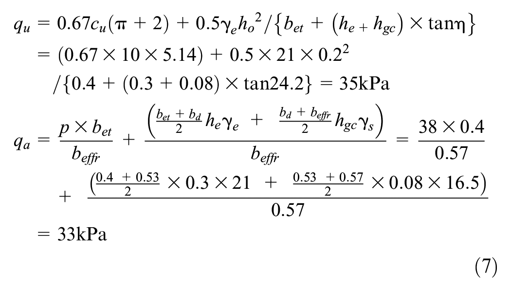
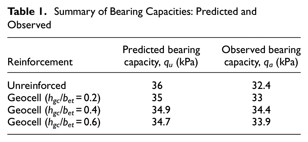
Similarly, calculations for all other cases were done, and a summary of the results obtained is presented in Table 1. It can be seen that the predicted and observed values are nearly the same. There is little reduction in the predicted bearing capacity, from the unreinforced to reinforced case, and with increase in height of the geocell mattress; which is attributed to reduced surcharge pressure because of reduced size of the triangular edge considered as the overburden. However, the predicted load carrying capacity (i.e., ultimate bearing pressure × width of the equivalent footing) has continued to increase with increase in the height of the geocell mattress (i.e., 15.8 kN/m for unreinforced case, and 19.9, 23.8, 27.3 kN/m for geocell reinforced cases with hgc = 0.2bet, 0.4bet, 0.6bet, respectively). The corresponding load carrying capacities obtained from the model test data are: 14.2, 18.8, 23.5, 26.7 kN/m, respectively. It can be seen that comparison between the predicted and observed bearing capacities, by load per unit run, is relatively close, which indicates that the proposed model can predict the bearing capacity of the embankment satisfactorily. Dividing the bearing capacity with the unit weight of the fill soil, the collapse height of the embankment (i.e., qu/γe) can be estimated.
Summary of Bearing Capacities: Predicted and Observed
Numerical Analysis
Results obtained from the model tests were verified through three-dimensional numerical analysis using the finite element software, ABAQUS (version 6.14; Dassault Systèmes Simulia Corporation, 2014). Soils in the foundation bed, geocell mattress, and embankment were modeled using hexahedral eight-noded reduced integration elements, C3D8R. The geocells were modeled using four-noded reduced integration membrane elements, M3D4R. The geometry of a typical finite element model used in the present study is shown in Figure 18. Numbers of elements in the soil and geocell domains were carefully selected through mesh sensitivity analysis. Vertical boundaries of the model were constrained against lateral displacements while its bottom boundary was constrained from displacements in all directions.
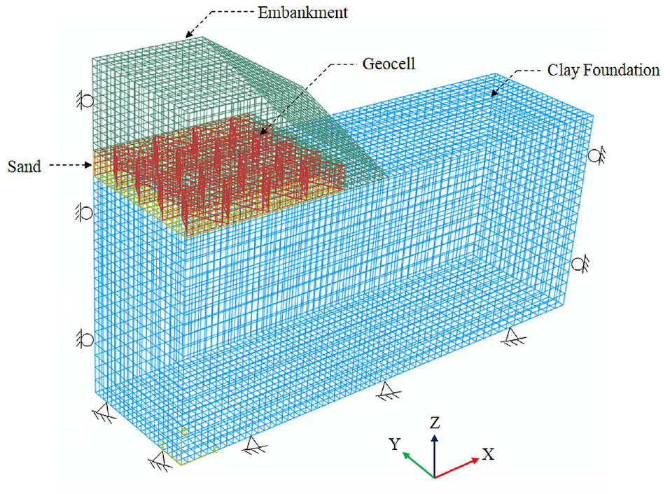
Typical finite element model.
The soft clay in the foundation bed and the clayey sand in the embankment were modeled as elastic-perfectly plastic material, obeying the Mohr-Coulomb yield criterion. The infill sand in the geocell mattress was simulated using elasto-plastic Mohr-Coulomb yield criterion with non-associated flow rule. Input parameters for these models were obtained through triaxial compression tests. The geocell was modeled as an elastic material because no visible damage was observed during the tests and the strains developed were less than 0.15%. Its elastic modulus was determined from the stiffness obtained from the tensile stress–strain response. Details of the material properties used in the numerical analysis are summarized in Table 2. The geocell reinforcement was simulated as an embedded part inside the sand layer. This is similar to the approach followed by Satyal et al. ( 41 ). Loading was applied in two stages. First, gravity was applied to simulate the in situ conditions in the embankment and foundation bed. Second, the loading stage consisted of applying uniform pressure to the crest of the embankment at increments of 0.5 kPa.
Summary of Material Properties Used in the Finite Element Analysis
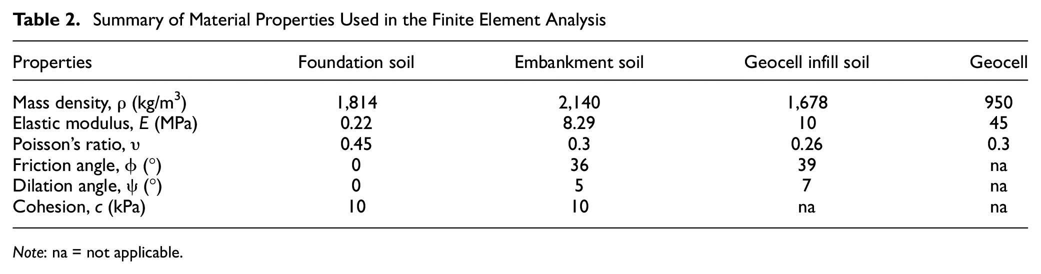
Note: na = not applicable.
Comparison between the numerically predicted and experimentally observed pressure–settlement responses of the embankment, for unreinforced and geocell reinforced cases, are presented in Figure 19. It can be seen that the test and simulated results match reasonably well, which indicates that the numerical model is able to predict the pressure–settlement behavior of the embankment satisfactorily. Numerically obtained lateral displacement contours, as depicted in Figure 20, exhibit that relatively large lateral displacements developed in the toe region of the embankment decreased significantly with provision of geocell reinforcement. This is very similar to the experimental observations shown in Figure 14. Similarly, the numerically obtained vertical displacement contours were also in very good agreement with the experimental results. These findings further substantiate the load carrying mechanisms observed through the model tests as discussed earlier.
Comparison of predicted and observed pressure–settlement responses.
Horizontal displacement contours from finite element model (surcharge pressure, p: 29 kPa): (a) unreinforced and (b) geocell reinforced (hgc/bet = 0.6).
Using the validated finite element model, full-scale embankments were analyzed. The prototype embankment had a crest width of 8m and side slope of 1:1. The material properties used were similar to those of the model tests (Table 2). As in practice, the embankment construction was simulated in lifts. Each lift was formed by a layer of finite elements onto which gravity was applied. Because of symmetry, only half of the embankment was simulated. Typical results obtained are presented in Figure 21. The net embankment height here is defined as the height of the embankment minus the settlement it has undergone as recorded at its center. It can be seen that, initially, with increase in the embankment height, the net height continues to increase to a maximum value, beyond which it tends to decrease. Initially, when the embankment loading is relatively low, the foundation soil tends to be stable and thereby settles less, leading to increase in the net height. At later stages, as the fill height increases, the foundation soil tends to yield and settle more, and the net embankment height is reduced. At one stage, when the settlement tends to be greater than the thickness of the fill added, the net height of the embankment decreases, leading to failure ( 38 ). The corresponding embankment height is referred to as the failure height.
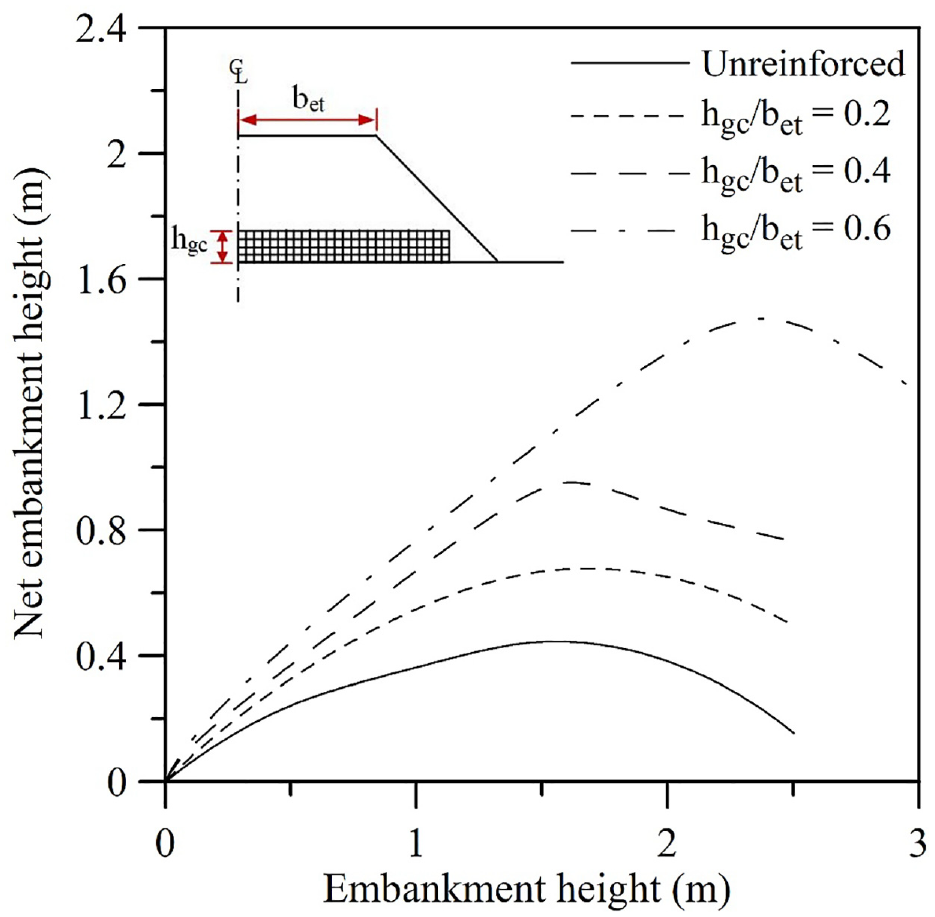
Predicted, net versus total embankment height for prototype case.
The prototype analysis data depicted in Figure 21 indicates that failure height of the unreinforced embankment is around 1.5 m and that of the embankment with geocell reinforcement (hgc /bet = 0.6) is around 2.4 m. Similar observations were made in the model tests as well, where the corresponding failure heights were around 1.6 m and 2.6 m, respectively. This is possibly because, with the saturated undrained condition, the friction angle of the foundation soil tends to be zero leading to practically negligible scale effect. From Figure 21, it can also be seen that the net embankment height, which in the unreinforced case was only about 0.44 m, with geocell reinforcement (hgc/bet = 0.6) increased to 1.48 m, an improvement of the order of 3.3 fold. This finding once again establishes the influence of geocell reinforcement in enhancing the performance of embankments over soft soil as observed in the model tests. Therefore it can be said that the general mechanisms and behavior of geocell reinforced embankments observed in the model tests can be reproduced at large scale.
Conclusions
This research effort investigated the influence of geocell reinforcement on the load carrying mechanism of embankments over soft soil. A series of instrumented model tests and numerical analyses were carried out. Based on the results obtained, the following conclusions can be made.
Provision of geocell-sand mattress beneath an embankment on soft soil can enhance its performance, in both increased bearing capacity and reduced settlement. Correspondingly, the embankment fill height can be increased significantly. With geocell reinforcement of height equal to about 30% of the embankment crest width, the fill height can be increased by 60%.
While an unreinforced embankment on soft clay, because of differential settlement, tends to disintegrate, with geocell reinforcement it continues to behave as a monolith up to a high surcharge pressure/fill height. As the geocell mattress behaves like a wide slab, it restrains the embankment against punching down onto the soft clay below, and thereby inhibits differential settlement, leading to improved performance of the system.
With geocell reinforcement, the embankment loading tends to be dispersed over a wider area, reducing stress intensity in the foundation bed and consequently reducing heaving. The geocell mattress, because of its rigidity, forces upon a deep seated failure in the foundation bed and thereby widens the rupture surface significantly. Consequently, increased shear resistance is mobilized, leading to enhanced bearing capacity. Moreover, because of its relatively greater tensile strength and significant rough interface from the pocket openings, the geocell mattress restrains the embankment fill against lateral sliding and shares the resulting stresses effectively. Consequently, the fill soil remains stable up to high surcharge pressure and thereby opens up the possibilities of constructing embankments of relatively greater height over soft soil.
Strain measurements from within the geocell mattress suggest that its efficacy in restraining the fill soil against instability is relatively higher toward the central crest of the embankment and that the end portion contributes in a secondary manner by deriving anchorage through mobilization of passive resistance from the surrounding soil. Once the embankment soil tends to crack, strain increment in the geocell wall tends to decrease. This suggests that the reinforcing efficacy of the geocell mattress is also dependent on the stability of the fill soil, so for better performance improvement the embankment should be made of relatively strong soil.
With geocell reinforcement the load dispersion angle is increased significantly, which establishes the efficacy of the geocell reinforcement in redistributing the embankment loading over a wider area. With increase in height of the geocell mattress, its rigidity tends to increase, leading to reduced deformations in the embankment and giving rise to increase in the load–spread angle. Considering the stress dispersion zone as an equivalent footing, the bearing capacity of unreinforced and geocell reinforced embankments were analyzed. The predicted values were found to be in close agreement with the experimentally observed ones.
The model test data were compared with the predictions of a finite element model (ABAQUS Version 6.14). The results indicate that the finite element model is able to simulate satisfactorily the behavior of unreinforced and geocell reinforced embankments over soft soil. Analysis of prototype embankments indicates that the general behavior observed in the model tests was reproduced at large scale.
Footnotes
Acknowledgements
The authors wish to thank Dr. Sanjay Nimbalkar, University of Technology Sydney, Australia, for his kind suggestions for the numerical study. The authors are thankful to the anonymous reviewers for their valuable comments for improving the presentations in the paper.
Notations
The following symbols are used in this paper:
bd = width of stress dispersion zone at base of the embankment;
bet = crest width of the half model embankment;
beffu = width of the equivalent footing in unreinforced case;
beffr = width of the equivalent footing in reinforced case;
bgc = width of geocell mattress;
Cc = coefficient of curvature of soil;
Cu = coefficient of uniformity of soil;
c = cohesion of soil;
D10 = effective mean size of soil particles;
E = modulus of elasticity;
he = height of embankment;
hgc = height of geocell mattress;
ho = height of triangular edge adjacent to the equivalent footing;
Nc, Nq, Nγ = bearing capacity factors;
p = applied surcharge pressure on embankment crest;
qu = ultimate bearing resistance;
qs = equivalent overburden pressure;
qa = applied surcharge pressure;
s = settlement of embankment;
γe = unit weight of embankment soil;
γs = unit weight of sand fill in geocell;
δ = resultant displacement of soil particles;
δh = horizontal displacement of soil particles;
δv = vertical displacement of soil particles;
η = stress dispersion angle;
ρ = mass density;
υ = Poisson’s ratio;
ϕ = friction angle of soil;
ψ = dilation angle of soil
Author Contributions
The authors confirm contribution to the paper as follows: study conception and design: S. K. Dash; data collection: R. Saikia; analysis and interpretation of results: S. K. Dash, R. Saikia; draft manuscript preparation: S. K. Dash, R. Saikia. All authors reviewed the results and approved the final version of the manuscript.
Declaration of Conflicting Interests
The author(s) declared no potential conflicts of interest with respect to the research, authorship, and/or publication of this article.
Funding
The author(s) disclosed receipt of the following financial support for the research, authorship, and/or publication of this article: The financial support for conducting this research work was provided by Indian Institute of Technology Kharagpur through recurring grant.
Data Accessibility Statement
Most of the data used during the present study are included in the paper. The few data not reported in this paper, are available from the corresponding author by request.