
Abstract
Engineers and planners today face challenges of assessing and adopting emerging propulsion technologies for commuter rail, particularly battery and hydrogen power. Early 20th century experiences with electrification technology may offer useful perspectives. When electrifying in the early 20th century, the most important decision facing North American commuter railroads was choosing electrical specifications—first between direct current (DC) and alternating current (AC), and then selecting a voltage. As a result, today’s electrified railroads present a sometimes-confusing array of specifications. Beneath the seeming disorder of specifications for legacy installations lies a logic based on the timing and circumstances of electrification, and on the ultimate size and purpose that railroads envisioned for these electrifications. Only low-voltage DC, delivered via third rail, was available for the earliest electrifications. By 1907, AC had entered the scene, and various overhead-wire DC specifications appeared between 1911 and 1930. Since the mid 20th century, 25,000 V AC at commercial frequency has become the default standard for new electrifications (and re-electrifications of older installations). Yet, even this standard has not been adopted for all reinforcements of overhead-wire electrifications, because of the historical overhang of earlier decisions. In situations where standardization of electrical specifications is not feasible, interoperability of equipment may be a more important priority.
As commuter rail agencies seek to reduce their carbon footprints, emerging propulsion technologies—particularly battery power and hydrogen—are receiving closer examination ( 1 , 2 ). Electrification, where appropriate, may also become increasingly attractive if otherwise justified. How should 21st century planners and engineers seeking to reduce commuter railroading’s effects on the environment assess and adopt new technologies? What are the opportunities and risks of early versus later adoption? The experiences of early 20th century commuter railroads in North America may be instructive, particularly as several of these properties still use electrical specifications that have changed little since the early 20th century.
Although 25,000 V alternating current (AC) at 60 Hz is the norm for new railroad electrifications (see Table 1 for a list of abbreviations), early 20th century choices of electrical specifications still make themselves felt. Nowhere in North America is electrification more widespread than in the Northeast Corridor (NEC) between Boston, Massachusetts, New York, and Washington, D.C. Yet, the situation in the NEC appears confusing:
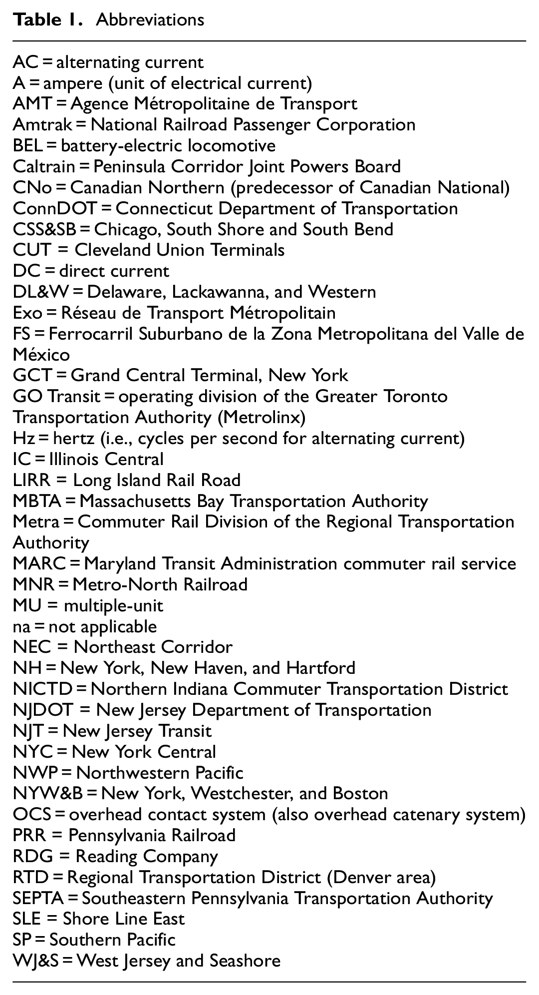
Abbreviations
In Connecticut, state-sponsored Shore Line East (SLE) trains between New Haven and New London run primarily on Amtrak’s 25,000 V AC, 60 Hz electrification, installed for Amtrak’s own intercity passenger trains. On reaching New Haven, SLE and Amtrak trains, now on Metro-North Railroad (MNR), use 12,500 V AC, 60 Hz.
On MNR, New Haven Line trains use 12,500 V AC, using an overhead contact (or catenary) system (OCS). Shortly before they enter New York City to reach Grand Central Terminal (GCT), they switch to a 700 V direct current (DC) third-rail system, with pickup shoes running underneath the third rail, to reach GCT.
MNR is planning New Haven Line service to New York’s Penn Station, where trains will use the Long Island Rail Road (LIRR)’s 750 V third-rail system with overrunning pickup shoes, because the overhead-wire system there uses 25 Hz AC, for which MNR’s trains are not properly equipped.
On New Jersey Transit (NJT), North Jersey Coast, Morris & Essex, and Montclair-Boonton trains leave New York using 12,500 V AC, 25 Hz. At outlying voltage change points, they switch to 25,000 V AC, 60 Hz.
Between Boston and Washington, D.C., Amtrak intercity passenger trains use three different AC electrical specifications: 25,000 V 60 Hz, 12,500 V 60 Hz, and 12,500 V 25 Hz.
Today, equipment interoperability makes these different currents and voltages workable, despite the apparently disordered specifications. However, a look at their history shows that these specifications are not as random as they seem.
From the first commuter rail electrifications in the early 20th century, the choices of electrical specifications continue to affect railroads today. This research has three main parts. First comes the history of electrification technology, along with the methods and sources used. Second, the various historical phases are considered: early installations from the 1900s using low-voltage DC with third rail, overhead-wire electrifications (both DC and AC) opened between 1907 and 1931, and modern electrifications and re-electrifications from the 1980s on. Third, various aspects of technology development are examined: power supply, substation spacing, overhead clearances, contact systems, and the dynamic tension between standardization and interoperability. Concluding thoughts are offered about future technological directions and the lessons for tomorrow’s technology choices from early 20th century railroads.
Historical Background
From as far back as the 1840s and 1850s, passengers have been regularly traveling between home and work by train. Soon, railroads were operating trains and ordering equipment with the needs of commuters in mind. By the mid 20th century many of these operations had become elaborate and intensive ( 3 , 4 ). Full-service, private sector railroads ran commuter trains on a commercial basis, subject to state and federal regulation. As with freight and intercity passenger trains, railroads sought to make money carrying commuters, although, in practice, profits from freight service cross-subsidized commuter trains.
Overregulation by the Interstate Commerce Commission and competition from publicly subsidized highways, airports, and waterways brought railroads into increasing financial distress, especially in the U.S. Northeast. The U.S. Congress and Canadian Parliament took several important steps to relieve railroads of their financial burdens, allowing them to focus on freight:
Creation of intercity passenger systems Amtrak (1971) and Via Rail Canada (1977)
Transfer of responsibility for commuter rail operations from Conrail to local agencies (1983)
Rail freight deregulation (1980 in the U.S., and 1987 in Canada), which made the rail freight business profitable
Meanwhile, state, provincial, and regional authorities took over financial and operating responsibility for commuter trains during the 1960s and 1970s ( 5 ). It is against this historical background that today’s commuter railroads have maintained and expanded electrification.
North American commuter rail electrification dates from the first decade of the 20th century ( 6 – 8 ). Railroads electrified at different times for different reasons, resulting in various choices of current and voltage ( 9 ). There are three distinct generations of railroad electrification technology, all of which still serve North American railroads ( 10 ).
First-Generation Electrification
Electrification technology evolved from low-voltage DC systems used by street railways and rapid-transit systems. The first installations on main-line railroads used low DC voltages (usually 660 V) delivered via third rail. At low voltages, only a large third rail can carry the high amperages (i.e., volumes of current) needed to power heavy trains (although overhead wire, with its lower current-carrying capacity, suffices for smaller, lighter streetcars and light-rail trains). Third-rail systems are now found solely on rapid-transit systems and two commuter railroads with low-clearance tunnels. The low voltages of these installations require frequently spaced electric substations. First-generation electrifications survive on LIRR and MNR in New York.
Second-Generation Electrification
By the 1910s, electrical manufacturers had developed higher-voltage alternatives using OCS, in DC and AC versions. DC was available at 1,200, 1,500, 2,400, and 3,000 V. Single-phase 11,000 V power at 25 Hz (the dominant frequency produced at the time) quickly became the preferred specification for AC: The lower the frequency, the smaller the … motor could be for a given horsepower output; that is, a motor of a particular size and weight operating at 25 cycles [per second, i.e., Hz] had a higher horsepower rating than an identical one operating at 60 cycles. As the frequency increased, so did the dimensions of the motor … to maintain a specified horsepower. … For railroads, this was vital. An electric locomotive had to pack as powerful a motor as possible into a very restricted space (
11
).
The relationship between AC frequency and motor size no longer holds true, first with the rise of on-board rectifiers in the mid 20th century allowing AC-powered equipment to use DC motors, and then with the late 20th century development of three-phase AC motors controlled by varying the frequency of the current ( 12 ). However, in the early 20th century, motor size was crucial for railroads—and not just those using AC.
Some early 20th century electrical engineers argued for AC on the grounds that wayside electrical hardware costs could be up to 15% lower than for DC. Countering this, DC proponents noted that “motors, controls, transformers, and other equipment required on A.C. motor cars increased their weight by anywhere from 15 to 25 percent over that for comparable D.C. motor equipment” ( 13 ).
Commercial rivalry between General Electric and Westinghouse Electric, which recommended DC and AC systems, respectively, may have influenced some choices. However, after 1915, multiple commuter railroads were using each current, allowing properties to make informed decisions about different specifications based on operating experience.
Early 20th century railroads electrifying for suburban service alone generally preferred DC, as it required no heavy, space-consuming transformers on board to reduce the voltage to levels that traction motors could process. However, AC was often preferable for longer distances and heavy power draw, such as with long freight trains, because its high voltages made it easier to transmit power across longer distances with fewer substations and less voltage loss between substations ( 10 , 14 , 15 ). Second-generation AC electrifications survive on the NEC between New York and Washington, D.C., Philadelphia and Harrisburg, Pennsylvania, and on Philadelphia’s commuter rail system. DC installations survive in Chicago, Illinois, and northwest Indiana.
Third-Generation Electrification
On-board rectifiers, allowing AC-powered equipment to use DC traction motors, appeared in the mid 20th century ( 6 ). This enabled railroads to switch to commercial-frequency power once older AC equipment (requiring low-frequency power) had been retired. 25,000 V AC at commercial frequency (60 Hz in North America and 50 Hz in much of the rest of the world) emerged in postwar France and became the norm for new and renewed installations, although it is not necessarily optimal for all OCSs. Examples of third-generation systems include electrifications in Denver, Colorado, and northern California.
Table 2 summarizes the principal characteristics of these specifications, including all three generations of electrification.
General Characteristics of Different Electrical Specifications
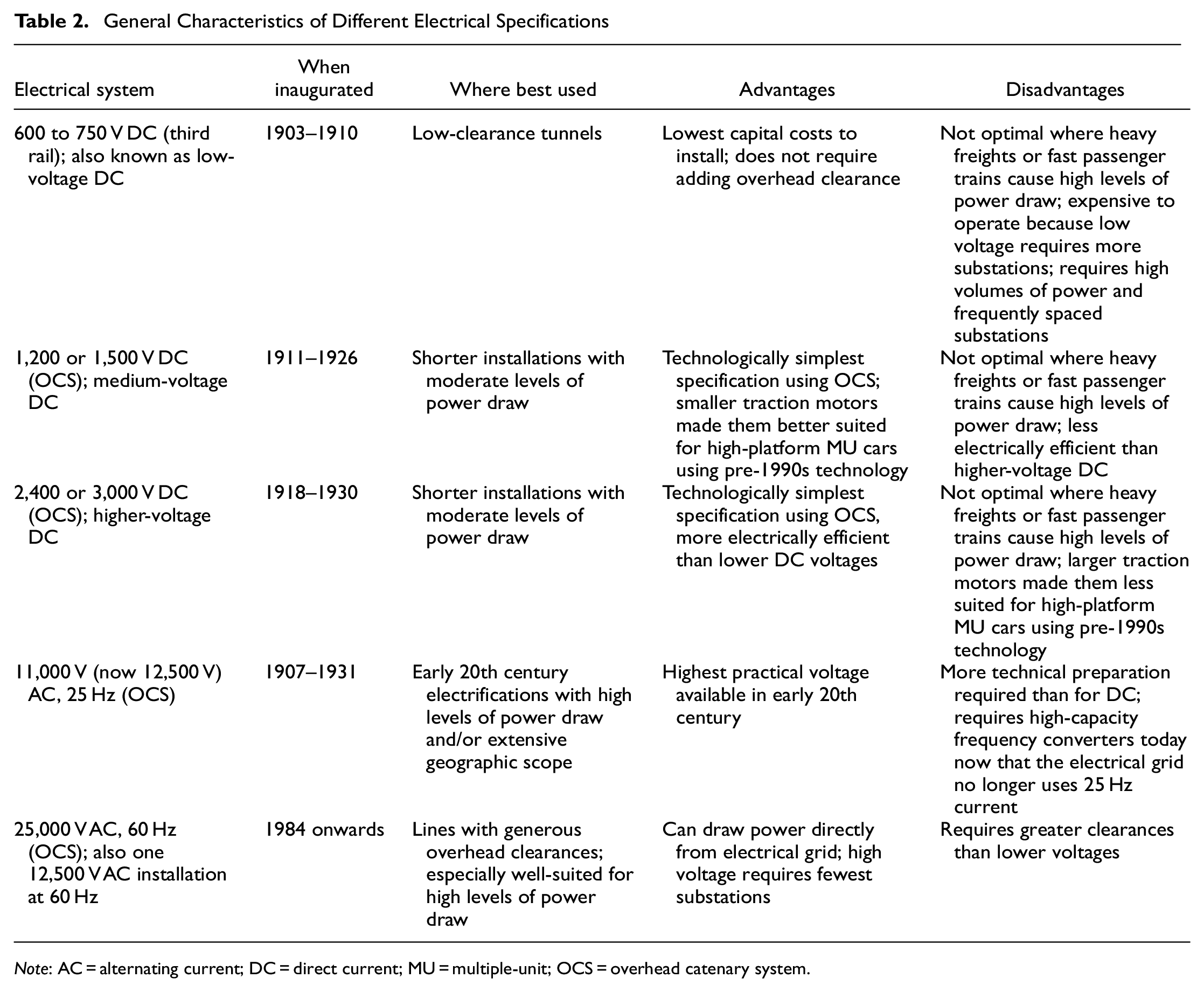
Note: AC = alternating current; DC = direct current; MU = multiple-unit; OCS = overhead catenary system.
Methods and Sources
This analysis focuses on the choice of electrical specifications for those railroad electrifications in the U.S., Canada, and Mexico, whether existing, discontinued, or being installed as of 2023, that are or were largely for commuter and/or intercity passenger trains. Of particular importance for understanding the choice of specifications are:
The specific needs that electrification sought to address
The types of train that each electrification was intended to accommodate
Each railroad’s operating requirements
The electrical specifications available when each railroad decided to electrify
Examining these elements together showed clear patterns in the choice of technology that may not be apparent without the broader picture.
Railroads Included
In addition to commuter rail, intercity passenger rail was also included. Non-commuter electrifications considered here include: the former Cleveland Union Terminals (CUT) installation in Ohio’s largest city, a short intercity passenger electrification that resembled contemporary commuter rail electrifications; the surviving elements of the Pennsylvania Railroad’s (PRR) installation in the NEC; and Amtrak’s 2000 electrification between Boston and New Haven, Connecticut, North America’s first new-start main line railroad electrification since 1931 (aside from a freight corridor in Mexico that was electrified for only 2 years) ( 6 , 16 ). Re-electrifications are noted in passing, but have been covered in more detail elsewhere ( 10 , 17 ).
Several discontinued commuter rail electrifications were included, as they differed little in their electrical technology from their surviving contemporaries ( 18 ). Also, the Chicago, South Shore, and South Bend (CSS&SB), an electrified commuter railroad that originated as an electric interurban railway, was included ( 13 ). Other interurbans were not considered here, as most of them used 600 V DC, the electrical standard for most street railways ( 19 , 20 ). Most interurbans arose during the first decade of the 20th century, when few other specifications had been proven reliable.
Electrified freight operations did not automatically disqualify any railroads from inclusion ( 21 ). PRR and New York, New Haven, and Hartford (NH) had large freight as well as commuter and intercity passenger elements to their electrifications, and several commuter rail electrifications had small freight components. However, other railroads with electrified freight service were excluded when no commuter service was involved.
Two railroads operating entirely with diesels in early 2024 were included. The Caltrain electrification between San Francisco and San Jose, California, was expected to open in 2024, and GO Transit in the Toronto, Ontario, Canada area was in the process of electrifying several lines. However, the Massachusetts Bay Transportation Authority (MBTA) was not included, as the status of its electrification plans was uncertain at the time of writing. MBTA is planning to electrify its Fairmount Line in Boston, which diverges from and then reconnects with Amtrak’s NEC main line. MBTA already operates diesels under the wire on Amtrak between Boston and points in Massachusetts and Rhode Island.
The basic-technology 600 V electrification of the Boston, Revere Beach, and Lynn was excluded ( 22 ). This narrow-gauge line differed little from interurbans in its electrification technology, as it used low-voltage DC with OCS. Nor were the Port Authority Trans-Hudson or the Staten Island Railway included. Both are rapid transit properties which are subject to the Railway Labor Act and Federal Railroad Administration safety oversight because they were formerly owned by main-line railroads.
Unimplemented commuter rail electrification proposals are not discussed here. To the extent that railroads had decided on a combination of current and voltage by the time these proposals were halted, their specifications largely resembled those in use elsewhere ( 23 ). The only exception was a 1910 study undertaken by New York Central (NYC) subsidiary Boston and Albany at the behest of the Massachusetts legislature, for a 21 mi, 1,200 V DC electrification with third rail ( 6 , 24 ). Normally such a medium-voltage DC electrification would use overhead wires.
Table 3 shows basic data for electrifications involving commuter and/or intercity passenger trains. SLE service in Connecticut (diesel-operated until 2022) is noted in the Amtrak Boston–New Haven entry.
Basic Data for North American Commuter and Intercity Passenger Rail Electrifications
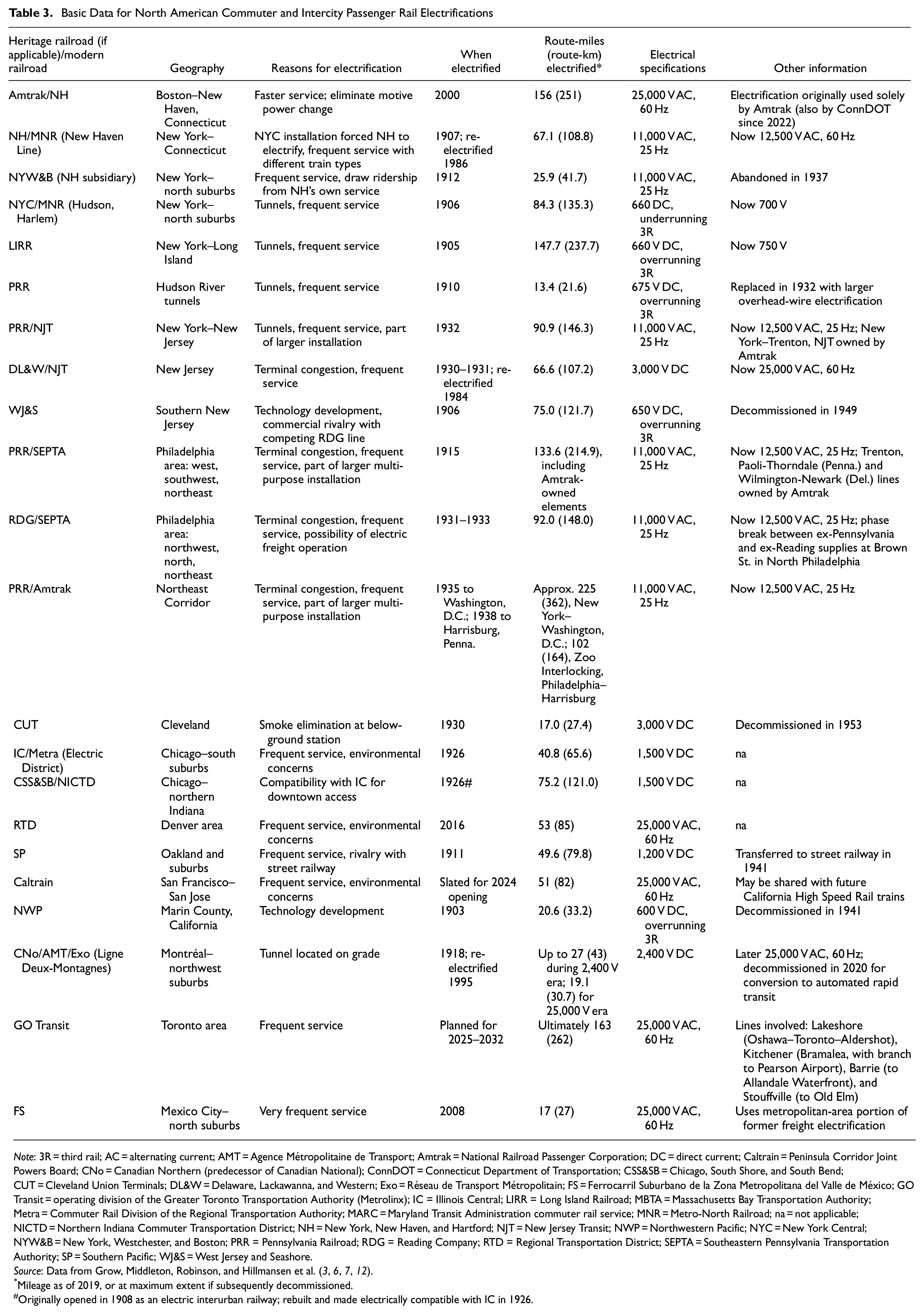
Note: 3R = third rail; AC = alternating current; AMT = Agence Métropolitaine de Transport; Amtrak = National Railroad Passenger Corporation; DC = direct current; Caltrain = Peninsula Corridor Joint Powers Board; CNo = Canadian Northern (predecessor of Canadian National); ConnDOT = Connecticut Department of Transportation; CSS&SB = Chicago, South Shore, and South Bend; CUT = Cleveland Union Terminals; DL&W = Delaware, Lackawanna, and Western; Exo = Réseau de Transport Métropolitain; FS = Ferrocarril Suburbano de la Zona Metropolitana del Valle de México; GO Transit = operating division of the Greater Toronto Transportation Authority (Metrolinx); IC = Illinois Central; LIRR = Long Island Railroad; MBTA = Massachusetts Bay Transportation Authority; Metra = Commuter Rail Division of the Regional Transportation Authority; MARC = Maryland Transit Administration commuter rail service; MNR = Metro-North Railroad; na = not applicable; NICTD = Northern Indiana Commuter Transportation District; NH = New York, New Haven, and Hartford; NJT = New Jersey Transit; NWP = Northwestern Pacific; NYC = New York Central; NYW&B = New York, Westchester, and Boston; PRR = Pennsylvania Railroad; RDG = Reading Company; RTD = Regional Transportation District; SEPTA = Southeastern Pennsylvania Transportation Authority; SP = Southern Pacific; WJ&S = West Jersey and Seashore.
Mileage as of 2019, or at maximum extent if subsequently decommissioned.
Originally opened in 1908 as an electric interurban railway; rebuilt and made electrically compatible with IC in 1926.
A few words are in order about how Table 3 shows the extensive ex-PRR electrification, as distinct elements of this far-flung installation have different owners, and significant portions have two users operating with electric traction. There are separate entries for Amtrak, NJT, and the Southeastern Pennsylvania Transportation Authority (SEPTA). The latter two have extensive trackage rights on Amtrak. Mileages are double-counted where SEPTA and NJT run on Amtrak, so the totals for each electrification should not be added up for a total of electrified route-miles.
In Philadelphia, there are separate entries for the former PRR and Reading Company (RDG) electrifications. These were operationally unified in 1984 with the opening of the Center City Commuter Connection, a tunnel with a new station (Market East, now Jefferson Station) located beneath and replacing the former Reading Terminal ( 25 ). Suburban Station, the former PRR terminal, is a crew change point for most trains and is now the functional starting point for both the PRR and RDG sides, which are shown separately despite the operational overlap between the two (PRR-side trains going out of service in Center City are stored on the RDG side, and vice versa). There is a phase break between the PRR- and RDG-side electric supplies north of Center City on the RDG side. Although the overhead wire is continuous and insulated at the transition point, trains coast through a short neutral section in both directions.
There is no entry in Table 3 for the Maryland Transit Administration (MARC)’s service. MARC’s Penn Line operates on Amtrak between Washington, D.C., Baltimore, and Perryville, Maryland, but has no plans to replace its aging electric locomotives and now operates mostly with diesels under the wire.
Sources Used
William Middleton’s definitive book about railroad electrification was an invaluable source for this research ( 6 ). Other books and articles were consulted, both about electrification technology in general and about individual commuter railroads. Most of these were histories written after the fact, but a few contemporary sources were also included. In all instances, sources were perused for information about the characteristics of different electrical specifications and each railroad’s operating needs.
An unexpectedly helpful source was John Droege’s Passenger Trains and Terminals ( 26 ). This important early 20th century reference discusses the characteristics of DC, single-phase AC, and three-phase AC, which required a clumsy two-wire system and never caught on in North America. Acknowledging that there was no single “best” specification, this book nevertheless described the characteristics of different systems in a way that was accessible to non-technical managers.
Surprisingly, early 20th century references devoted to railroad electrification rarely discussed the choice of current and voltage, crucial though this was (24, 27–30). Two of these devoted several pages to the advantages and disadvantages of the different specifications then available, but these discussions fell short of offering guidance ( 24 , 28 ).
Choosing Specifications: It Depends
Railroads electrified for various reasons at different times and under differing circumstances. The underlying patterns may not be readily apparent now, but the choices that they made were far from random ( 31 ). Current and voltage choices have affected the capital and operating costs of electrifications and their overhead clearance requirements, as well as what types of service the installation could readily serve.
This research has identified only one official source explaining a North American railroad’s choice of specifications ( 32 ). Nevertheless, the stages of technology development and the operating needs of the various electrifications, readily available from the historical literature, strongly suggest why different railroads chose differing specifications.
Patterns in Current and Voltage Choice
For any given set of circumstances—operating needs, types of train to be accommodated, and what technologies were available—either one or, at most, two types of specification were reasonably suited to those circumstances. The choice of current and voltage followed logically from when the railroad was electrifying, over what distance, and why.
Among the first to electrify were New York commuter railroads, which chose third rail when that was the only option. Third rail also went well with their low-clearance tunnels. Other electrification options became available around 1905, and the choices that railroads made corresponded closely to their needs. Most railroads operating (or planning to operate) freight as well as commuter trains with electric traction chose 11,000 V AC. Otherwise, railroads usually chose DC systems. Since the 1980s, commercial-frequency AC, usually at 25,000 V, has been the preferred (if not quite universal) specification for new and upgraded installations.
Figure 1 shows when railroads inaugurated electrifications at what voltages between 1903 and 1931 (subsequent re-electrifications and other changes in voltage are not indicated). Figure 1a shows the situation for all commuter railroads, and 1b focuses on DC systems. There was a clear, if uneven, increase over time on DC-adopting railroads from Southern Pacific’s (SP) 1,200 V in 1911 to Delaware, Lackawanna, and Western (DL&W)’s 3,000 V in 1930–1931. 11,000 V AC was the preferred, although not universal, choice for commuter railroads contemplating electric freight operations. Table 4 shows this information categorized under individual railroads and the functions that their electrifications served.
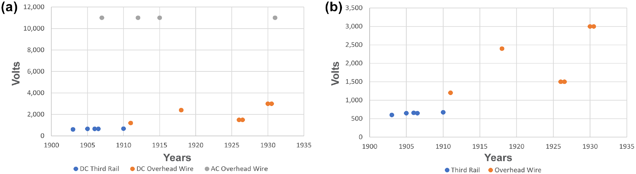
Progression of original electrification voltages for North American commuter railroads, 1903–1931: (a) direct current (DC) and alternating current (AC) and (b) DC only.
Commuter Rail Electrifications, 1903–1931, by Railroad, Type of Specification, and Function
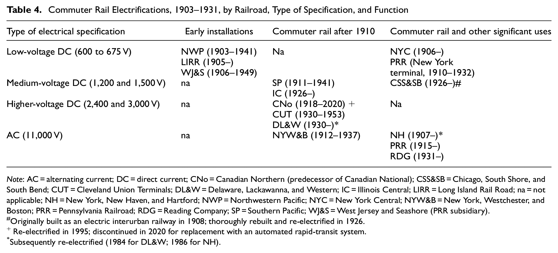
Note: AC = alternating current; DC = direct current; CNo = Canadian Northern (predecessor of Canadian National); CSS&SB = Chicago, South Shore, and South Bend; CUT = Cleveland Union Terminals; DL&W = Delaware, Lackawanna, and Western; IC = Illinois Central; LIRR = Long Island Rail Road; na = not applicable; NH = New York, New Haven, and Hartford; NWP = Northwestern Pacific; NYC = New York Central; NYW&B = New York, Westchester, and Boston; PRR = Pennsylvania Railroad; RDG = Reading Company; SP = Southern Pacific; WJ&S = West Jersey and Seashore (PRR subsidiary).
Originally built as an electric interurban railway in 1908; thoroughly rebuilt and re-electrified in 1926.
Re-electrified in 1995; discontinued in 2020 for replacement with an automated rapid-transit system.
Subsequently re-electrified (1984 for DL&W; 1986 for NH).
Properties that needed to electrify most urgently—New York railroads with low-clearance tunnels—were among the earliest adopters, when low-voltage DC with third rail was the only proven technology available. Starting with the 1911 SP electrification, most railroads electrifying primarily for commuter service chose DC using OCS. No railroad adopted third rail after 1910. Where freight and intercity passenger service became a significant factor, railroads tended to choose 11,000 V AC.
Higher voltages provide greater electrical efficiency, though this advantage has been counteracted by other factors, as discussed below. The higher the voltage, the longer railroads may transmit electricity between substations before the drop in voltage between substations affects train performance.
The most fundamental tradeoff in electrification is that the higher the voltage (i.e., electrical pressure) that a railroad adopts, the lower the amperage (i.e., amount of current) that it needs to produce a given level of wattage (i.e., power to move trains). Figure 2 shows the relationship between volts and amperes for first, second, and third-generation electrifications. The vertical axis shows voltage, and the horizontal axis shows amperage. Voltage-amperage points are shown for a 10-car commuter train, representing (from lower right to upper left) a first-generation, third-rail 660 V DC electrification circa 1910 (e.g., NYC), a second-generation, 1,500 V DC electrification circa 1930 (e.g., IC), a second-generation, 11,000 V AC electrification circa 1930 (e.g., PRR), and a modern third generation, early 21st-century, 25,000 V AC electrification (e.g., Caltrain in northern California). The same train requires 5,000 A at 660 V but only 130 A at 25,000 V.
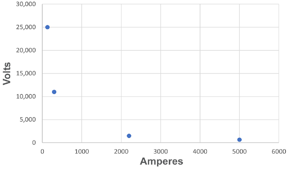
Tradeoff between voltage and amperage for a 10-car commuter train.
These different electrical specifications and their optimum uses are now considered in more detail.
Early Installations
Two commuter railroads, Northwestern Pacific (NWP) in Marin County, California, just north of San Francisco (1903) and PRR subsidiary West Jersey and Seashore (WJ&S) in southern New Jersey (1906), electrified with third rail for technology development and (in the latter case) commercial rivalry, rather than to accommodate large passenger volumes ( 18 , 33 , 34 ). Both were abandoned during the 1940s.
Two larger third-rail electrifications endure today. The first was the 1905 installation on the LIRR (a PRR subsidiary at the time), which needed to electrify the approaches to its Brooklyn, New York, terminal when much of the access thereto was placed underground ( 35 ). The LIRR electrification, which expanded greatly during the 1920s with further extensions in 1970 and 1988, still operates with third rail ( 6 ).
The next, opening a year later, was on the NYC, which was required by state law to electrify its Park Avenue tunnels in Manhattan in the aftermath of a serious accident in 1902 caused by poor visibility because of steam locomotive smoke ( 36 , 37 ). Figure 3a shows NYC’s electrification with third rail protected by cover boards.
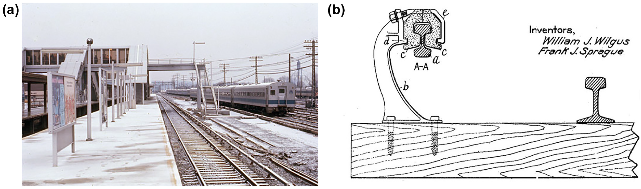
First generation, early 20th century third-rail electrification, New York Central (NYC): (a) NYC electrification, Croton-Harmon, New York, 1976 and (b) cross-section of NYC underrunning third-rail system.
To prevent ice buildup on the third rail, particularly for its extensive running along the Hudson River, NYC used an unusual underrunning system, with the live rail suspended above the pickup shoe ( 38 ). Figure 3b shows a cross-section of NYC’s underrunning system.
PRR opened another third-rail installation in 1910 to serve its Pennsylvania (now Penn) Station in Midtown Manhattan. It extended from Jamaica, Queens, New York, a crucial junction on LIRR with that railroad’s already-electrified Brooklyn line, to Pennsylvania Station, and then on PRR to Manhattan Transfer, a power-change point east of Newark, New Jersey ( 11 , 39 ). In 1932, PRR replaced the New Jersey third-rail electrification with a much longer 11,000 V AC installation. Only the portion used by LIRR trains remains in use.
Later Electrifications for Commuter Rail
The last third-rail electrification, that is, using first-generation technology, opened in 1910. Second-generation technology was emerging in both DC and AC forms. DC’s relative simplicity and the ability to operate trains without transformers on board still recommended it to railroads electrifying largely or entirely for commuter service. SP was the first to adopt DC using OCS for its 1911 Oakland, California-area installation, choosing 1,200 V, twice the standard street railway voltage of 600 V ( 40 , 41 ). “Since much of the SP suburban system operated in the streets of the East Bay communities, a third-rail installation was out of the question” ( 6 ). Although SP carried large volumes at the time, it electrified largely to keep up with a rival street railway and did not grade-separate its lines before electrifying.
For its 1918 electrification of a new line reaching downtown Montréal through a 3.2 mi tunnel, Canadian Northern (CNo) (predecessor of Canadian National) chose 2,400 V DC, twice SP’s voltage ( 42 , 43 ). CNo, a late entrant, found it more economical to build a tunnel (costly though that was) than to assemble land for surface access. Perhaps surprisingly, CNo based its choice of specifications (and even the design of its electric locomotives) on the 1913 electrification of the Butte, Anaconda, and Pacific, a Montana heavy-haul copper mining railroad also using 2,400 V DC ( 6 , 43 ).
Illinois Central (IC) operated a very frequent commuter service, with many local stops at 0.5 mi intervals on Chicago’s South Side, as well as south suburban stations placed further apart ( 44 – 47 ). Although no tunnels were involved, IC had very frequent service in its closer-in portions, akin to rapid transit. Nevertheless, IC delayed its decision to electrify until 1919, when it reached an agreement with the city allowing it to rearrange and expand its congested main line in return for electrifying. The terminal improvements included making changes to the elevation of the right-of-way, widening the alignment, and arranging the tracks in their final positions. Only when those prerequisites were completed did the railroad electrify, a process completed in 1926 ( 48 – 50 ).
For its electrification, IC considered four specifications: 750 V DC (with third rail), 1,500 V and 3,000 V DC, and 11,000 V AC, 25 Hz. IC chose 1,500 V “on the basis that it was a terminal electrification only” ( 32 ). The article did not discuss IC’s reasoning further, but third rail would have required many more substations and was poorly suited for IC’s two street-level branches with their frequent grade crossings. AC would require transformers aboard the cars, but IC’s short station spacing required rapid acceleration, for which the weight of transformers would not be helpful.
Nor might 3,000 V DC have been the best fit for IC. With the technology then available (i.e., before variable-frequency three-phase AC motors), on “1500 V systems, the motors are usually wound for 750 V … On 3000 V [systems], the motors must be wound for 1500 V. As a result, they are larger in diameter and more difficult to install under the low floors of multiple unit [rolling] stock” ( 51 ). Even before electrifying, IC used high platforms exclusively, so the floor height of its multiple-unit (MU) cars mattered. Japan, the Netherlands, and Melbourne and Sydney, Australia, where high platforms were the norm, also adopted 1,500 V DC.
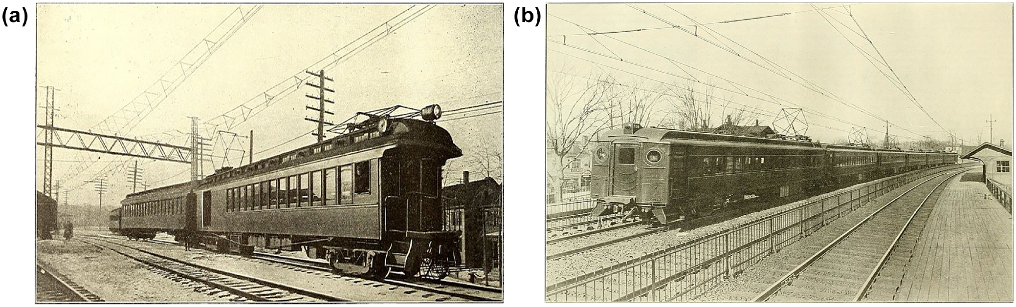
By contrast, DL&W had no high platforms during the 54-year life of its 3,000 V electrification, making the floor height of its cars less critical. Figure 4 shows the IC and DL&W electrifications at typical inner-zone stations, with their respective high and low platforms. DL&W operated a more far-flung suburban service than IC, with low-platform stations on co-mingled steam railroad tracks. It ran roughly half as many trains as IC did, on half again as many route-miles ( 15 , 52 ). DL&W’s choice of 3,000 V allowed it to roughly double the spacing of its substations relative to IC. Possible electrification of freight and intercity passenger service also influenced DL&W’s choice of 3,000 V. “Due to the interrelation between the commuter service and mainline passenger trains, this system was readily adaptable … and freight locomotives of this voltage were available” ( 53 ).
Second generation, early 20th century direct current electrifications: (a) Illinois Central, 55th-56th-57th Streets, Chicago, IL, 1967 and (b) Delaware, Lackawanna, and Western electrification, Orange, NJ, 1968.
Similarly, the 3,000-V CUT electrification used locomotives to pull intercity passenger trains to and from a low-platform station, so the relationship between traction motor size and platform height was not an issue there, either. Installed to eliminate steam locomotive smoke from a station built underneath extensive air-rights office building development, the electrification lasted until 1953, by which point diesels had taken over from steam ( 6 ).
Two railroads chose AC for commuter-only electrifications. NH built subsidiary New York, Westchester, and Boston (NYW&B) as a largely self-contained commuter railroad in the New York City borough of the Bronx and north suburban Westchester County. Its failure to reach Manhattan shortened its life (1912–1937).
Chartered in 1904, NYW&B originally planned a third-rail electrification compatible with the New York City subways. Then, a year later, parent railroad NH decided on 11,000 V AC for its own electrification. “Whether there was any serious debate about which system to use is now unknown, but if so, compatibility with the New Haven won out” ( 54 ). Initially, NH provided NYW&B with electricity from its own power plant but, starting in 1915, NYW&B began using commercially bought power (which was more readily available by then).
RDG chose 11,000 V AC for its Philadelphia, Pennsylvania, commuter service, as it planned to extend electrification beyond the suburban zone for freight and intercity passenger trains ( 55 ). However, RDG’s electrification opened in 1931 during the Depression, and those extensions never materialized.
Combined Commuter and Freight Electrifications
Some railroads preferred AC because it helped them meet the power requirements of long, heavy freight trains. AC had its drawbacks: it had a greater effect on signal systems than DC, its use required that metal items along the right-of-way, such as fences, be grounded, and early 0.5 second circuit breakers at substations were not fast enough to prevent extensive damage in the event of short circuits ( 11 ). Short circuits also wreaked havoc on telephone systems, and it was not until the 1920s that electrical manufacturers developed 0.04 second breaker switches that solved these problems. However, AC also made it easier to supply higher amperages of current with fewer substations en route, so AC-adopting railroads persevered. On the positive side, AC electrification avoided problems with electrolysis affecting DC railroads.
In 1907, NH opened its 11,000 V AC electrification ( 56 ). Having to use electric equipment to reach GCT when its Manhattan landlord, NYC, electrified, NH decided to place its power change point well beyond the junction with NYC ( 57 ).
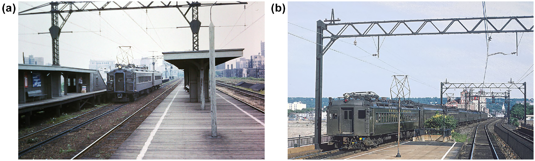
Given that decision, NH had several reasons not to adopt NYC’s third-rail system. One was distance. NH saw the need to electrify not only to Stamford, Connecticut (then the de facto end of the suburban zone) but also to New Haven, an important division point. Low-voltage third rail would be electrically inefficient over such distances. Furthermore, NH may have envisioned extending electrification beyond New Haven to Boston (which Amtrak implemented in 2000). Figure 5a shows NH’s electrification, which in its first stage used a distinctive triangular catenary system to increase the stability of the overhead wires. For later extensions east of Stamford, NH used a more conventional design.
Second generation, early 20th century alternating current electrifications: (a) New York, New Haven, and Hartford electrification, Stamford, CT, 1909 and (b) Pennsylvania Railroad multiple-unit cars on the Philadelphia–Paoli, Pennsylvania Main Line, 1915.
Second, NH anticipated using electric traction for fast intercity passenger trains and heavy freights as well as commuter trains, which favored the higher power capabilities of AC. Finally, legal questions surrounded third rail on NH, which had installed a handful of experimental, exposed-surface third-rail installations on some branch lines in Connecticut. A lawsuit by the state and one of the cities en route, brought on public safety grounds, forced the railroad to dismantle these electrifications ( 6 ). Even with NYC’s underrunning contact surfaces protected by cover boards, NH could not count on being allowed to use third rail in Connecticut.
The low-clearance Brooklyn tunnels forced PRR’s subsidiary LIRR to use third rail. However, PRR saw its third-rail installation between New York’s Pennsylvania Station and Manhattan Transfer as a transitional measure until AC had proven itself reliable ( 11 ).
PRR began 11,000 V AC operation between Philadelphia and Paoli, Pennsylvania, in 1915 ( 58 – 60 ), seeing this busy suburban segment as eventually being part of a much larger installation also powering intercity passenger and freight trains. Figure 5b shows this initial electrification. PRR followed this in 1918 with electrification of a short branch to Chestnut Hill West ( 61 ). There was a pause, during which PRR was able to evaluate the performance of AC and found it reliable. Expansion resumed, and by 1928, PRR had an extensive Philadelphia-area electrification. AC electric service started between New York and New Brunswick, New Jersey, in 1932, replacing the short third-rail Manhattan Transfer installation. In 1933, PRR closed the gap to Trenton, New Jersey, (already electrified from Philadelphia), allowing all-electric service from New York to Philadelphia and Wilmington, Delaware. Intercity electrification to Washington, D.C. and Harrisburg, Pennsylvania, followed in 1935 and 1938, respectively ( 6 , 11 , 62 , 63 ). The ex-PRR voltage was raised to 12,500 V by 1979.
CSS&SB was the only DC commuter railroad with a substantial freight service. CSS&SB’s predecessor was an electric interurban railway opened in 1908 using 6,600 V AC, 25 Hz, which was lowered to 700 V AC for three street-running segments ( 13 ). Although its 6,600 V system did not take full advantage of the capabilities of AC, this 75 mi railroad needed only two AC substations, as opposed to nine in 1967 with 1,500 V DC ( 15 ). Given its long distances and its freight service, CSS&SB might have been better off with AC (perhaps raised to 11,000 V) and dual-current equipment such as NH’s, with 1,500 V DC capability when on the IC and for street running. However, the AC installation was life-expired when new management took over in 1925 and modernized the railroad. Re-electrification at 1,500 V DC had the advantage of matching IC’s installation. Both railroads adopted that voltage during the summer of 1926 ( 13 ).
Postwar Era
The mid 20th century development of on-board rectifiers allowed locomotives and MU cars to draw AC but use simpler DC motors. Utilities had earlier switched from 25 to 60 Hz AC, allowing railroads to use 60 Hz AC once earlier universal-motor equipment (such as PRR’s well-known GG-1 electric locomotives) had been retired. By the late 20th century, three-phase, variable-frequency AC traction motors provided superior acceleration and energy savings for DC- and AC-powered railroads alike. These innovations facilitated the adoption of third generation electrification technology, allowing railroads to draw power directly from the electrical grid, unrestricted by the capacities of DC rectifiers or AC frequency converters. The failure of an aging frequency converter (since replaced) on the ex-Reading greatly disrupted commuting to the north of Philadelphia for several days in 1979 ( 64 ).
Commercial frequency 25,000 V AC emerged in Europe after World War II ( 65 ). Entering widespread use in France, Britain, Japan, and elsewhere, it is the preferred specification for most situations ( 66 ).
North America’s first 25,000 V AC, 60 Hz electrification opened in 1984, when the New Jersey Department of Transportation (NJDOT) re-electrified the ex-DL&W lines to facilitate service to New York Penn Station (using the original overhead wires). Amtrak had planned to convert its ex-PRR lines from 11,000 to 25,000 V until that project was cancelled for cost reasons in 1979 (although Amtrak did raise the existing voltage slightly from 11,000 to 12,500 V). By that point, NJDOT was committed to 25,000 V, and made the changeover in 1984 ( 17 ).
Similarly, in Montréal, the Québec Ministry of Transportation replaced the ex-CNo 2,400-V DC electrification with 25,000 V AC in 1995, rebuilding the entire installation. Figure 6 shows both eras, including the lighter wires used for the higher voltage. This re-electrified operation, in turn, closed in 2020 for rebuilding into an automated rapid-transit system like Vancouver, British Columbia’s Canada Line, but with 1,500 V DC OCS rather than the more typical third rail, because of Montréal’s winters.
Second and third generations: early 20th century direct current electrification and modern 25,000 V alternating current re-electrification, Montréal: (a) Canadian National near Vertu (now Montpellier), Montréal, Québec, Canada, during the 1980s (2,400 V DC era) and (b) Agence Métropolitaine de Transport, Montpellier, Montréal, Québec, Canada, 2002.
The 1986 re-electrification of the ex-NH New Haven Line, by then part of MNR, was also part of this wave. This installation, although technologically advanced, was underpowered, and its future between Stamford and New Haven was uncertain during the 1950s ( 67 ). By the 1970s, with high-performance air-conditioned cars taxing the power supply, load dispatchers were routinely faced with the need to cut out power during peak hours to avoid tripping substation circuit breakers when power draw threatened to exceed supply ( 16 ).
Upgrading to 25,000 V was not a realistic option, as high ridership meant that MNR could not afford to take cars out of operation to have their circuitry reworked for the higher voltage. Instead, MNR raised the voltage slightly from 11,000 to 12,500 V (which was within the tolerances of the equipment), and—most crucially—raised the frequency from 25 to 60 Hz to draw power directly from the electric grid. Because of an electromagnetic phenomenon known as inductive reactance, raising the frequency of the current without a corresponding increase in voltage causes a greater loss of voltage between feeding points to the OCS. MNR compensated for this by adding feeds.
New-start electrifications for intercity passenger and commuter rail have used 25,000 V AC exclusively. First was Amtrak’s 2000 electrification between Boston and New Haven, installed to speed intercity passenger service and eliminate a cumbersome locomotive change at New Haven ( 16 ).
Next, Mexico City, Mexico’s Ferrocarril Suburbano had its origins in a short-lived 25,000 V rail freight electrification—inaugurated in 1994 but decommissioned and taken down by 1997—to provide clearances for double-stack container trains ( 68 ). Authorities left an inner portion close to Mexico City in place. Commuter rail service opened on most of this segment in 2008 ( 69 ). This is the only form of local transportation other than the city’s overburdened streets and overcrowded urban metro.
The systems in Denver, Colorado (2016) and the San Francisco–San Jose corridor, as well as the electrification in progress in Toronto, similarly chose 25,000 V. The San Francisco and Toronto electrifications responded to high ridership ( 9 ). After Denver-area voters approved a major rail transit expansion program based on light rail, the track-owning railroads would not let the Regional Transportation District (RTD) build light rail in shared corridors, but they were willing to have commuter rail equipment near their trains. Having thus chosen commuter rail, RTD established that, for the frequent service that voters had been promised, electrification delivered a lower life-cycle cost than diesel MUs ( 70 ).
Technology Development and Tradeoffs
The options available to electrifying railroads in the first third of the 20th century involved tradeoffs as they sought to optimize (or at least satisfice) with the technology available when they chose electric traction. Technology improvements have alleviated some tradeoffs and created others, as these examples show.
Power Supply and Equipment Characteristics
Initially, railroads had to generate their own electricity, which became a limiting factor for NH ( 67 ). The last newly electrifying commuter railroad to build its own generating plant was SP, which inaugurated electric service in 1911 ( 71 ). In 1913–1914, PRR became the first railroad to arrange for a utility company to supply power for its electrification ( 11 ). Utilities and railroads worked closely together in these situations. Chicago-area electric companies not only supplied power, but also built and operated substations for IC and CSS&SB ( 13 , 72 , 73 ).
Since the 1960s, high-performance cars with air conditioning have required railroads to provide more electric power. With high-performance cars from the 1970s and 1980s, the rate of acceleration decreased as speed increased. However, newer cars with variable-frequency AC traction motors, such as LIRR’s and MNR’s M-7 and M-8 MU cars or Philadelphia’s Silverliner-Vs, continue accelerating at high rates until reaching the desired speed.
Supplying more power is the price that railroads pay for faster-accelerating, more comfortable equipment. Some properties have reinforced their existing systems, and others have re-electrified with commercial-frequency AC.
Substation Spacing and Voltage
One advantage of higher voltages is the ability to space substations further apart, an issue related to the voltage-amperage tradeoff illustrated in Figure 2. Figure 7 shows the relationship between line-miles and substations for DC systems at several different voltages for 1931, 1967, and 2010. The two New York railroads using third rail had similar voltages and average distances between substations in 1967, so they appear as a single data point for that year. Both those systems had raised their voltages slightly by 2010. The two higher-voltage DC railroads were re-electrified with AC in the late 20th century and do not appear for 2010. AC systems are not shown, as their situation with transformer and feeder substations complicates visual analysis somewhat, as does the lack of 1931 data for PRR’s electrification.
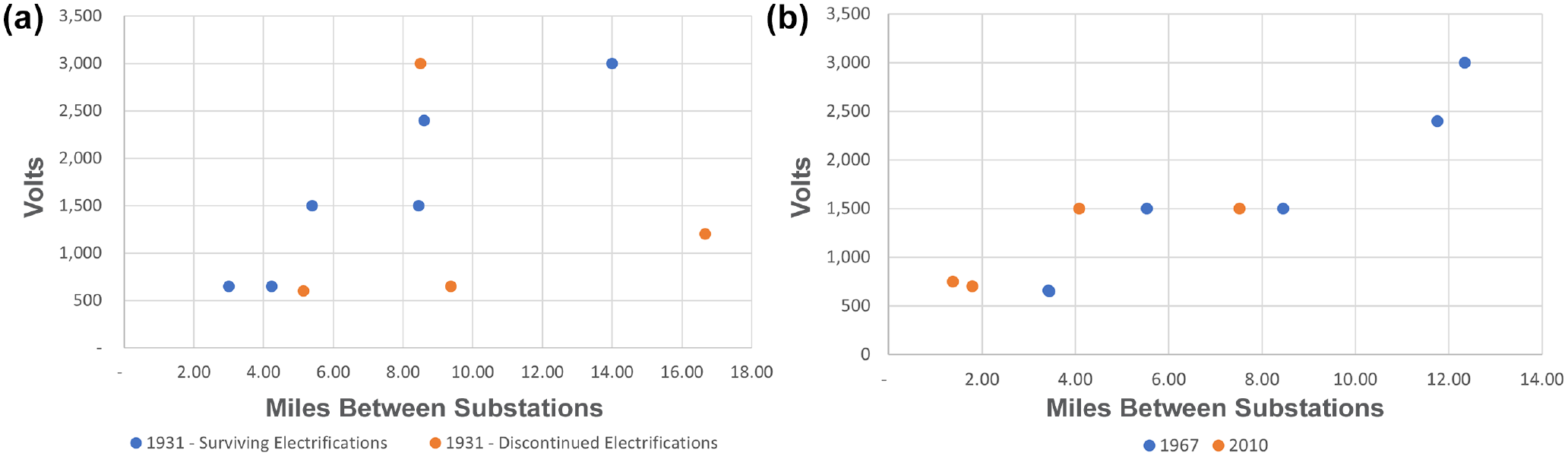
Relationship between voltage and line-miles per substation for direct current systems: (a) circa 1931 and (b) circa 1967 and circa 2010.
All the remaining DC-using railroads added substations between 1967 and 2010, thus reducing the average distance per substation and shifting their data points to the left. This reflects the need to provide enough power for today’s high-performance, air-conditioned cars. (Railroads can also increase the capacity of substations, an option not captured in Figure 7.)
The two 1,500 V operations show marked differences in substation spacing for both years, which reflects differences in their respective environments. In Chicago, he Metra Electric has frequent service with many train starts; the South Shore Line covers longer distances with greater spacing between stations and fewer trains, especially toward the outer end.
Power Supply and Overhead Clearances
Despite the progression from low-voltage, third-rail DC to commercial-frequency 25,000 V AC, historical factors still affect commuter railroads. There is no prospect of replacing third rail with OCS in MNR’s Park Avenue tunnels in Manhattan, or LIRR’s tunnels in Brooklyn. Even where clearances allow OCS, 25,000 V AC is not suited for all electrifications.
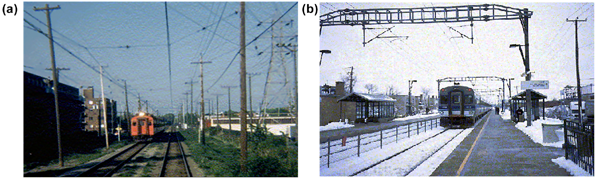
Rather than switch to AC, Metra reinforced its ex-IC 1,500 V DC system by converting tie-stations (which house section insulators) into substations ( 74 ). When IC originally electrified the line in 1926, there were generous overhead clearances for its single-level cars, as Figure 4a shows. Adopting double-deck cars starting in 1971 used most of the space available overhead. Metra was concerned that the increased clearances needed for 25,000 or even 12,500 V might require extensive civil engineering work at several bridges above the railroad, such that the capital costs would exceed the operating savings over the lifetime of the investment ( 15 , 75 ). Figure 8a shows the tight fit of the overhead wires near a bridge over the railroad, relative to the cars’ pantographs.
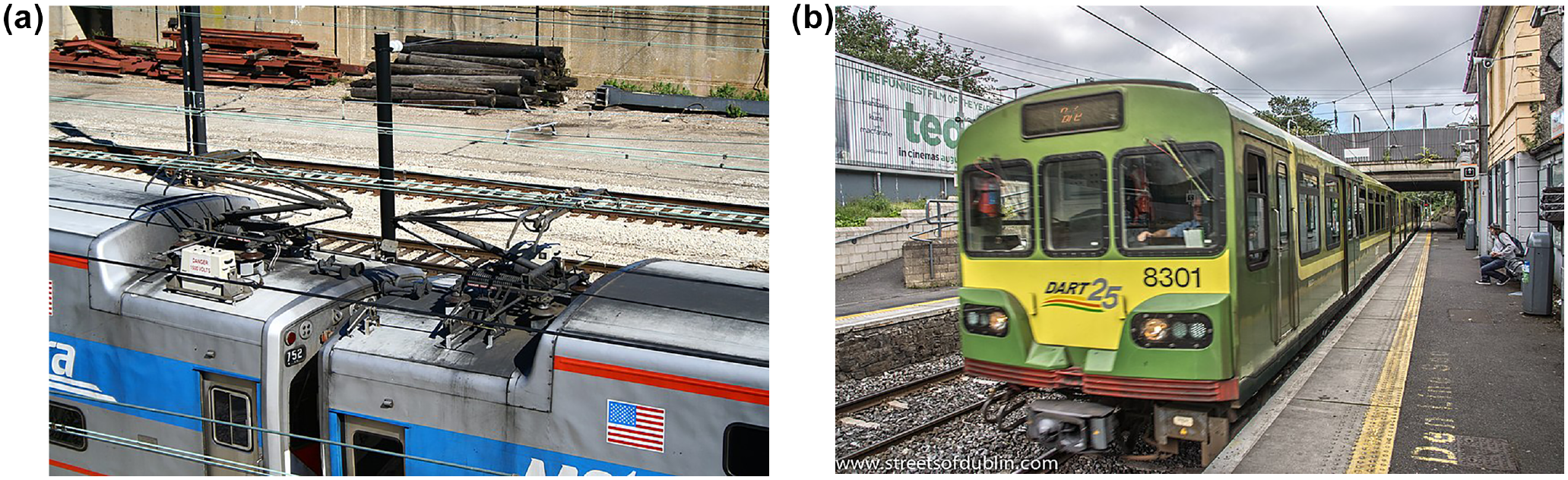
Low clearances on 1,500-V direct current electrifications: (a) Metra Electric, near 11th St., Chicago, IL, 2006 and (b) Dublin Area Rapid Transit electrification, Iarnród Éireann, Raheny, Ireland, 2012.
The overhead clearance issue has also arisen in other parts of the world. In Scotland, British Rail’s south suburban Glasgow electrification, which uses a terminal with low trainshed clearances, opened in 1962 at a risk-averse 6,250 V AC. After careful investigation, it was found safe to adopt 25,000 V, which was implemented in stages between 1967 and 1973, in time to be incorporated into a 25,000 V electrification linking Glasgow with London in 1974.
For its 1984 Dublin Area Rapid Transit electrification, Iarnród Éireann (IÉ), the national railway of the Republic of Ireland, chose 1,500 V DC. IÉ concluded that the capital cost of providing clearances for 25,000 V at low bridges, as in Figure 8b, and tunnels outweighed the operating cost savings of high-voltage AC. Much as IC did in the 1920s, IÉ rejected 3,000 V to avoid the need to fit larger traction motors beneath cars on a high-platform operation ( 51 ).
The clearance issue, however, may be less challenging than is sometimes thought. The British Standards governing infrastructure design on Network Rail have established that 25,000 V can be used safely with clearances as low as 10.5 in. (267 mm) between the overhead wire and the highest point on the equipment ( 66 ). Even lower clearances may be possible with short neutral sections in the OCS if trains have the momentum to coast through them. Of course, unless MU cars have multiple pantographs (and electrical connections between cars), or electric locomotives have small batteries, trains will lose auxiliary power when they are unable to draw current. Neutral sections may also be useful for voltage changes, again assuming trains can coast through these short segments.
Contact Systems
Each generation of electrification has its distinct electrical contact systems. First-generation installations used third rail, as overhead wires lacked the volume to transmit the amperages needed to move heavy trains with low-voltage DC.
Second-generation systems used elaborate contact systems (6, 76–78). Because the upper, messenger wires were strung from one support to the next, they made a slight curve known in geometry as a catenary curve, therefore the term “catenary” wire.
Vertical so-called hanger wires transmitted power directly from the messenger to the contact wire on yard and other slow-speed tracks. On main line tracks, though, railroads needed to make the contact (trolley) wire as firm and level as possible for operation at speed. To accomplish this, railroads used so-called compound catenary designs, with the hangers connected to an auxiliary messenger wire just above the contact wire, connected by small clips, usually two between each hanger. Figure 9a shows these features. Figures 5b and 6a show the use of cable stays rather than steel crosswise elements to stabilize catenary wires across the right-of-way.
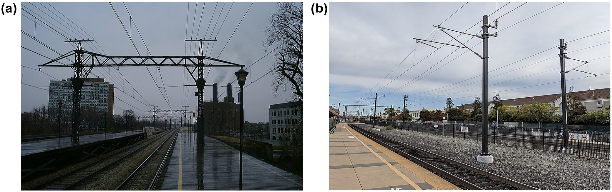
Second-generation variable-tension and third-generation constant-tension catenary: (a) Metra Electric, 59th St., Chicago, IL, 2002 and (b) Caltrain, Santa Clara, CA, 2021.
These wires were strung for many miles as a single element. Because they experience winter tightening and summer sag, they are described as “variable tension” wires. To manage these temperature-induced changes, railroads seasonally insert and remove short sections of wire. A failure to keep the wires tight can lead to destructive pantograph entanglements with the hanger wires caused by pantograph bounce and wire sway. PRR went to great lengths to avoid entanglements by carefully cantilevering the OCS with the hanger wires at an angle to maintain the contact wire directly above the track center, as seen in Figure 5b. Such accurate alignment helps avoid dewirements but concentrates wear on a short section of the pantograph contact strip.
Third-generation electrifications use modern OCS designs, as shown in Figure 9b, compatible with the fastest train operation (although the DL&W re-electrification reused the original wires, as did the NH electrification, at least initially). OCS design is distinct from the choice of current and voltage, but when newly electrifying or comprehensively replacing older overhead wires, railroads generally use constant-tension catenary, strung in sections of about 1 mi, with counterweights at both ends to keep the contact surfaces taut through winter cold and summer heat alike ( 79 ). Because this autotensioning keeps the wires taut, constant-tension systems use simple catenary, with hangers directly connecting the upper messenger wire with the contact wire. These installations usually provide a small amount of horizontal zigzag on straight track to distribute wear more evenly on the pantograph.
CSS&SB successor Northern Indiana Commuter Transportation District (NICTD) rebuilt its second-generation, variable-tension OCS with a constant-tension system to prevent dewirements, and MNR has done the same on the New Haven Line ( 80 ).
The Northeast Corridor Improvement Project, cancelled in 1979, would have not only raised the voltage between New York, Philadelphia, Harrisburg, and Washington, D.C. to 25,000 V AC, 60 Hz, but would also have installed constant-tension wire between New York and Washington. Without changing the voltage, Amtrak is replacing the original 1933 OCS (at the time of writing) with constant-tension wire on a largely straight section between New Brunswick and Trenton, N.J., excellently suited for fast running.
Standardization and Interoperability
Progress in electrification technology has largely removed one dilemma—the dynamic tension between standardization and interoperability. In the early 20th century, George Westinghouse called for standardization of specifications to help encourage the spread of railroad electrification ( 6 ). As a manufacturer, Westinghouse sought economies of scale from standardization, a goal not reached for electric railroad equipment, but one that makers of diesel-electric locomotives achieved after World War II when they found railroads would buy various standard, off-the-shelf models to meet specific operating needs.
Historian William D. Middleton, following Westinghouse’s logic, argued that the different specifications hindered electrification, even in its 1920s heyday: A persistent problem … was the failure to standardize systems and equipment. … Even where there was agreement on current and voltage, there were wide variations in power distribution systems and electric motive power. … [E]lectric motive power generally was custom-designed for each railroad just as steam power was. Thus the interchangeability and the economies of standardization were lost (
6
).
Yet railroads seem to have held a very different view. Standardization, had it been achieved, might have reduced the capital cost of electrifying. However, railroads appreciated the operational benefits of electrical specifications that closely matched their needs. The variety of electrical specifications made electrification more accessible for different railroads. Aside from NH, no railroad needed to use more than one electrical specification before the 1984 DL&W re-electrification.
Writing in 1916, John Droege, a senior NH operating official, pointed out that railroads needed to choose the specifications best suiting their needs: “The system of electrification must conform to the railroad’s needs; the reverse is impossible” ( 26 ). His position is particularly interesting, as his railroad operated extensively on NYC’s electrification, which differed completely in voltage, current, and pickup system. By implication, he identified interoperability, not standardization, as the critical need for electrified railroads.
This difference of perspective has been overtaken by technological improvements, as a brief review of interoperability on electrified railroads shows. In 1907, NH electrified its own line to the northeast of New York City with AC instead of adopting the DC system of NYC, where NH operated on trackage rights to reach GCT. As a result, NH needed to operate its MU cars and electric locomotives with two combinations of current and voltage. NH began electric operation on PRR in 1918, but this posed no problems because both railroads used the same specification at the time ( 67 ).
The initial solution was the “universal” motor. Although designed for AC power, it could also run on DC, thus the name. (Motors specific to AC existed, but it was difficult to control their speed with early 20th century technology.) Universal motors were less efficient than straight DC motors, offsetting some of AC’s superiority in electrical transmission because of the higher voltages involved.
The first interoperability breakthrough came after World War II, when manufacturers were able to offer locomotives and MU cars with on-board rectifiers, a technology that John Droege identified in 1916 as promising ( 26 ). This way, equipment drew AC from the wire, and, after the voltage was lowered via transformers, the resulting AC was fed through rectifiers for use in DC traction motors.
Finally, starting in the 1990s, variable-frequency, three-phase AC traction motors further refined electric traction (and, for that matter, diesel-electric locomotive technology). These motors can be fed from DC by inverting DC into three-phase AC, or from AC by rectifying the single-phase AC from the overhead wire into DC, and then inverting it into three-phase AC.
Thanks to these advances, MNR, NJT and Amtrak have little difficulty operating on different voltages and different currents. Although 25,000 V, commercial-frequency AC is the default choice for new electrifications, railroads can readily accommodate older specifications for through operation.
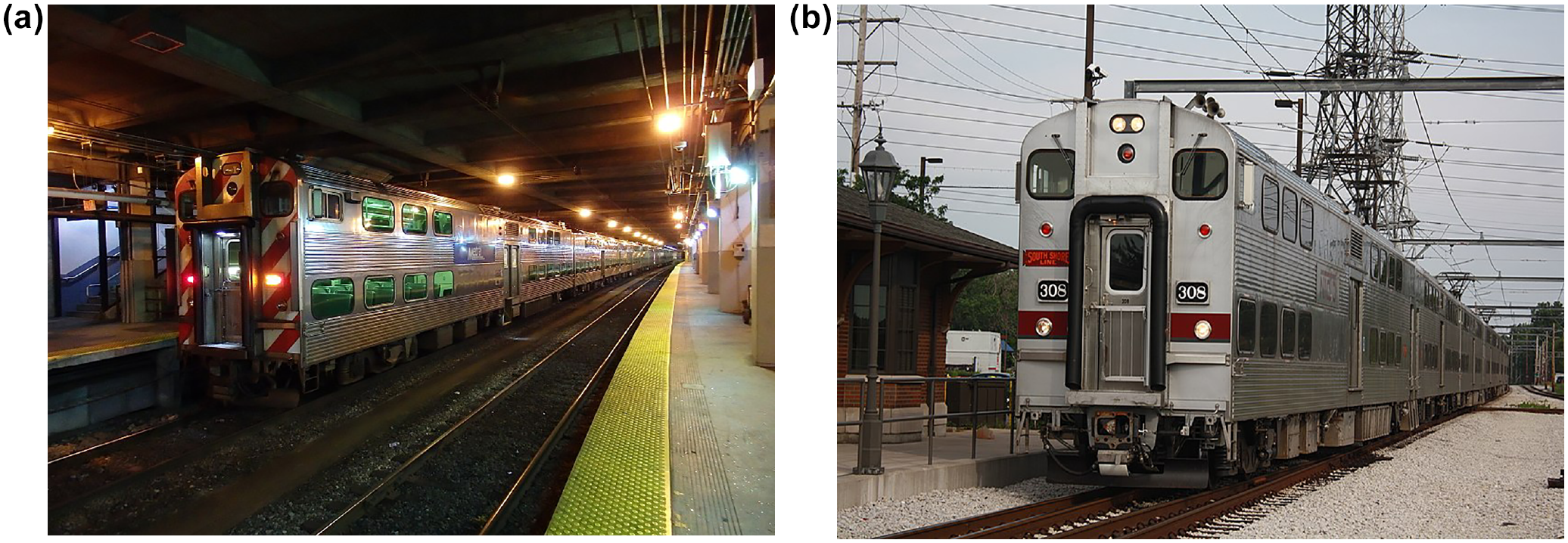
As for standardization, railroads have become more open to pooling orders or modeling their orders on recent builds for other railroads, as with the New York Metropolitan Transportation Authority, which has been placing joint orders for highly similar cars for LIRR and MNR since the late 1970s (Figure 10). Other systems have procured cars as follow-on orders to those delivered to other railroads. Thus, Denver’s cars are derivatives of Philadelphia’s Silverliner-V cars (Figure 11), and NICTD modeled a recent order on cars from the same builder for Metra Electric (Figure 12), although both sets of derivatives have slightly different door configurations from the original orders.
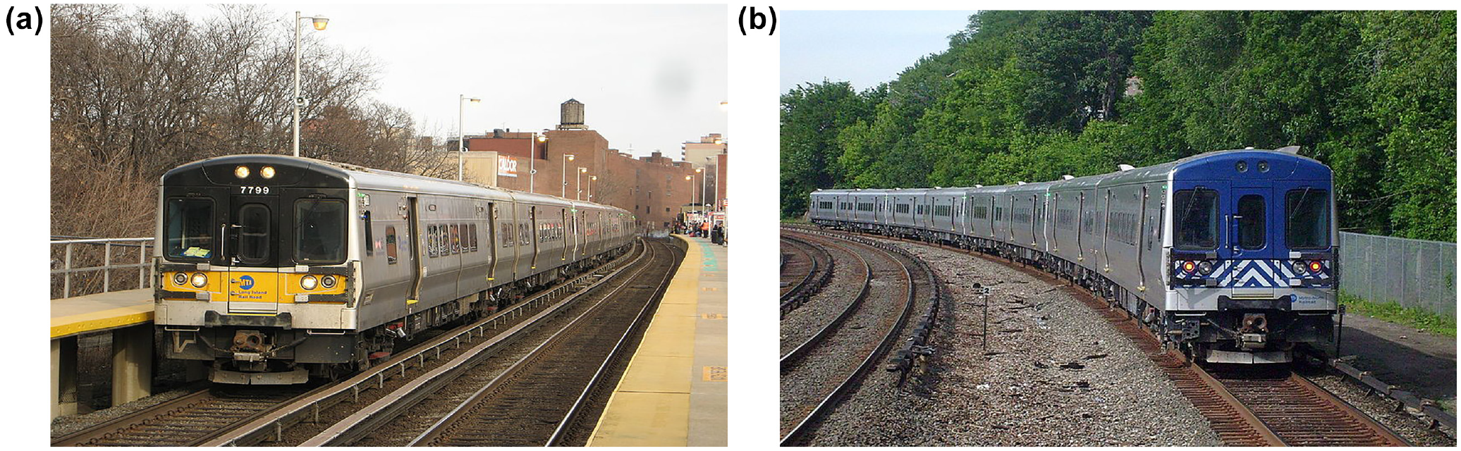
Joint equipment order for Metro-North and Long Island Rail Road (LIRR): (a) LIRR, Flushing, Queens, NY 2008 and (b) Metro-North Railroad, University Heights, Bronx, NY, 2014.

Initial and follow-on orders for Southeastern Pennsylvania Transportation Authority (SEPTA) and Regional Transportation District (RTD): (a) SEPTA, Jenkintown, PA, 2019 and (b) RTD, Denver Union Station, 2018.
Initial and follow-on orders for Metra and Northern Indiana Commuter Transportation District (NICTD): (a) Metra Electric, Millennium Station, Chicago, IL, 2017 and (b) NICTD, 2009.
Nevertheless, there are no off-the-shelf MU cars for the North American commuter market. There are too many differences in current collection, maximum height, and door requirements for there to be an industry standard, or even two standards—one for single-level and another for double-deck cars.
Standardization has costs as well as benefits. Manufacturing defects and the resulting removals of cars from service suggest that fleet standardization is not risk-free. One system hastily removed a third of its cars in 2016 for urgent repairs to their trucks. As with much else, standardization, too, involves tradeoffs.
Future Prospects
As commuter rail ridership recovers from the pandemic of 2020–2022 and resumes its earlier growth, systems will need to operate more, faster, and longer trains, possibly involving additional electrification. No unelectrified commuter railroads in major cities have low-clearance tunnels like those on LIRR and MNR, so any new electrifications are likely to use OCS at 25,000 V AC.
When electrifying or re-electrifying, the OCS must be fully insulated from support structures. Postwar experience on British Rail’s east suburban London electrification from Liverpool St. Station showed that insulators designed for 1,500 V DC were safe for 6,250 V AC ( 81 ), but this should not necessarily be extrapolated for higher voltages.
Further Re-Electrification?
Amtrak and commuter railroads using Amtrak’s NEC may yet switch to 25,000 V AC over the long run. All lines affected would have to be insulated for the higher voltage. Also, changes in electrification often require costly changes to signal systems. In the Philadelphia area, SEPTA’s Silverliner-V cars were built with 25,000 V capability. NJT’s locomotives routinely operate on both 12,500 and 25,000 V AC (although its MU cars can only make the change when stopped). Some of MNR’s M-8 cars on the New Haven Line have similar dual-voltage capability allowing them to provide SLE service between New Haven and New London, Connecticut.
Further re-electrifications of older DC installations are unlikely. Metro-North’s Park Avenue tunnels lack the clearances for OCS. LIRR’s line to Atlantic Terminal, Brooklyn (favored by many commuters for its proximity to downtown Manhattan) also has low-clearance tunnels that preclude OCS, as does LIRR’s 2023 extension to Grand Central Madison, below MNR’s GCT.
Metra Electric’s situation in Chicago has been noted above. The 16 ft 6 in. minimum clearance of Metra’s electric pickup wire at low overbridges comes within 8 in. of the 15 ft 10 in. roofline of the bilevel gallery cars in use, or 2.5 in. short of the minimum British Standards clearance for 25,000 V overhead wires ( 82 ). This helps explain Metra’s decision to reinforce its existing 1,500 V DC system rather than re-electrify.
Fourth-Generation Electrification?
So far, there have been three generations of electrification technology. Will a fourth generation emerge as concern grows about the relationship between greenhouse gas emissions and climate change? Thus far, commuter railroads have been paying attention largely to battery and hydrogen fuel cell technologies, which require electricity but do not involve electrification of the railroad itself ( 1 ). Although hydrogen is the favorite option for freight railroads, its low energy content makes it ill-suited for the frequent train starts of commuter railroading, which demand good acceleration for on-time operation.
Battery technology seems better fitted for commuter service, yet it makes poor use of the equipment because it would recharge only in storage. This manner of operation would be necessary on an unelectrified line where battery equipment would recharge solely at yards or downtown stations equipped with charging pads. However, if railroads consider the possibility of charging in motion from new or existing electrifications, it should be possible to use equipment more actively and eliminate diesel emissions, even those from dual-mode locomotives operating as electrics in electrified territory, without electrifying commuter railroads from end to end.
Recent research has shown in concept form the feasibility of using a combination of battery-electric locomotives (BELs) and battery tenders for energy storage to power commuter and intercity passenger trains in and beyond electrified territory, with charging in motion ( 2 ). Heretofore, railroads have electrified from one end of the line to the other to operate electrified service, but BELs would allow railroads to electrify as far as a substation will reach and then operate further in battery mode.
The key points for partial-electrification planning are that a 25,000 V AC substation can power overhead wires for about 25 mi in any direction before voltage drop affects operating capability, and that a combination of a BEL and battery tender can operate for about the same amount of time off-wire as is spent charging under the wire, assuming a prompt return to the electrified zone from the outer end of the line. Calculations show that BELs do not necessarily require high-voltage AC, but may recharge on older electrifications if this can be done without overloading substations (which may require capacity enhancements at some locations). If commuter railroads adopt battery-electrics with partial electrification, this would bring a fourth generation of railroad electrification technology into being.
Lessons from Early 20th Century Railroads
The choice of electrical specifications for commuter railroads since the early 20th century offers perspective for planners and engineers today, as commuter railroads examine new propulsion technologies. Railroads faced tradeoffs between simplicity and sophistication, and between capital cost and operating cost savings when choosing a current and voltage. Operating cost has mattered, but, if anything, ease of operation has been even more important.
Early adopters, of course, enjoy the use of new technologies sooner than railroads that take a wait-and-see approach. If a railroad can afford to wait, it may be beneficial in the long run to let emerging technologies develop (e.g., IC). But urgent needs may force some railroads to act sooner rather than later (e.g., NYC). Then there are intermediate situations where being operationally linked with an early adopter forces another railroad to innovate, but it does so with another specification (e.g., NH). These are practical, hands-on decisions that railroads must make as circumstances require.
Between 1905 and 1907, NH invested heavily in the promise of 11,000 V AC, only to see PRR derive more benefits from AC electrification as the technology matured. NH’s installation was technically quite advanced; indeed, Amtrak followed NH’s lead in using equalization technology for power distribution along its Boston–New Haven electrification. Yet PRR’s somewhat less sophisticated installation, which uses high-power lines to supply large volumes of current wherever needed, proved more robust ( 83 ). NH generated much of its own power before its 1986 re-electrification and suffered power shortfalls, whereas PRR waited until electric companies could provide all the power it needed.
Technological innovation has benefits, but also has risks. Some railroads were early adopters, and others made cautious choices, waiting for new technologies to mature. The choices that different railroads made illustrate the tradeoffs that large organizations face when weighing new technologies. LIRR and NYC needed to electrify through underground tunnels to reach central-area terminals at the start of the 20th century. Although raising tunnel clearances to accommodate OCS might have had long-run benefits, both railroads were under official pressure from state and city governments to electrify (as well as unofficial pressure in the form of increased ridership), and only third-rail specifications were then known to be capable of transmitting the required combination of voltage and amperage. Both installations operate reliably today because they have added substations to maintain sufficient power ( 15 , 84 ).
Alternatively, IC waited for the technology to mature. As early as 1908, the City of Chicago and civic groups were pressuring IC to electrify its commuter service ( 49 , 85 ). However, by waiting until 1919 to commit itself, IC was able to choose from a range of operationally proven electrical specifications and choose the one best suited to its needs.
As an example of how different railroads adapted to technology change when planning for electrification, historically, railroads (and street railways) used rotary converters (i.e., motor-generator sets) to turn AC into DC, losing over 10% of the energy to mechanical friction in the process. IC was the first to use large mercury-arc rectifiers. Still, the railroad hedged its bets, using the new rectifiers on only four of its seven substations ( 44 ). Four years later, DL&W used mercury-arc rectifiers exclusively at all its five substations ( 52 ).
Yet the use of mercury-arc rectifiers did not progress evenly. The two substations on the CUT electrification, an intercity passenger installation also opening in 1930, used motor-generator sets ( 86 ). This was by then a less technically advanced choice than mercury-arc rectifiers, but early-electrifying railroad NYC—which owned 93% of CUT—was familiar with rotary converters. Both technologies have since been superseded by solid-state rectifiers.
As the choice of current and voltage available to early 20th century commuter railroads shows, how railroads should approach new technologies today depends on their needs and the development of the technology concerned. However, the evolution of electrification specifications shows that there are both benefits and costs from taking on the risks of innovation and enjoying the benefits sooner versus waiting until a technology has matured.
The variation in specifications for early 20th century North American commuter rail electrifications, far from being disordered, corresponds closely to the needs of each railroad and the technologies available when electrifying. New installations are likely to use 25,000 V AC, although Chicago and Dublin show that the operating-cost savings of high-voltage AC may not justify the capital cost of raising overhead clearances to a safe level.
Decisions about electrical specifications are best left to the railroads that will live with the results for decades to come. Even with good intentions, externally-mandated specifications that may be forward-looking at the time may inadvertently prevent future innovation. Thus, in 1934 the Brazilian government chose 3,000 V DC as the standard for all future installations, precluding AC electrification which might have been more economic over longer distances ( 87 ).
The industry may be facing a new stage of technology choice as concern about climate change pushes commuter rail agencies to find alternatives to diesels. In propulsion as in all else, commuter railroads should seek the most efficient and durable technologies available. However, interoperability may be more practicable and more important than arbitrary standardization. The history of North American railroad electrification suggests that a flexible approach has allowed more railroads to benefit from electrification at times and in ways that best suited their circumstances. Similarly, as commuter railroads today address the challenges of moving toward carbon neutrality, they should seek practical solutions that best meet their operating needs while preserving flexibility and interoperability to the greatest extent possible.
Footnotes
Acknowledgements
The author thanks Alex Lu and the late John Aurelius for their perspectives about railroad electrification technology, and the reviewers for their informed, engaged, and helpful comments.
Author Contributions
The author confirms sole responsibility for the following: study conception and design, data collection, analysis and interpretation of results, and manuscript preparation.
Declaration of Conflicting Interests
The author(s) declared no potential conflicts of interest with respect to the research, authorship, and/or publication of this article.
Funding
The author(s) received no financial support for the research, authorship, and/or publication of this article.
The author’s interpretations do not necessarily reflect the official positions of any organization, past or present.