
Abstract
There are over 35 million concrete crossties (sleepers) installed in track in North America, with approximately 750,000 to 1,500,000 additional new ones installed annually. These components have been the focus of much research over recent years, which is resulting in significant advancements in their design and use. New solutions are addressing rail seat deterioration, abrasion, splitting, and other issues that have been associated with past derailments or have required major intervention. Moreover, concrete crosstie design is moving toward a performance-based approach, which is more efficient than the traditional prescription-based methods with generous safety factors. Smart crossties are also emerging, which go far beyond the traditional concepts of crosstie application. This paper presents an overall picture of the state of the art of concrete crossties in North America, linking fundamentals, industry challenges, design approaches, recent developments, and trends for the future.
The North American rail freight network is nearly 225,000 km in the United States, 42,550 km in Canada, and about 27,000 km in Mexico. In a typical year, freight railroads in the United States alone haul around 1.5 billion tons of raw materials and finished goods according to the Association of American Railroads ( 1 ). Such large figures add to the relevance of research and development of railroad track components.
The majority of railroad track worldwide consists of the rail, fastening systems, crossties (sleepers), ballast, sub-ballast, and subgrade ( 2 , 3 ). There are various crosstie materials, including wood (ranging from hardwood to bamboo and glued laminated timber), concrete, polymers (both thermoplastics and thermosets), and steel. Concrete is the second most common material used to manufacture crossties in North America and it is the dominant material used for crossties elsewhere in the world ( 4 , 5 ). Combining Class I heavy axle load (HAL) freight railroads, Amtrak, and rail transit properties, there are over 35 million concrete crossties in track in North America, with approximately 750,000 to 1,500,000 additional new crossties installed annually ( 6 ). Given its increased relevance, much research has been devoted to concrete crossties in recent years. The purpose of this paper is to facilitate further progress in the design and use of concrete railway crossties by summarizing recent advancements in North America and highlighting areas of future advancements.
The paper is composed of four major sections between Introduction and Conclusions. The first section provides a background of concrete crosstie common practices and challenges related to design, demands and failure modes. The second and third sections highlight the advancements that have emerged to improve concrete crosstie design philosophies and address their failure modes in North America. The fourth section is devoted to an analysis of possible trends considering the future of concrete crossties.
Background—Typical Design, Demand, and Failure Modes
Prestressed concrete crossties are commonly used in the most demanding service conditions in North America, such as freight railroad trackage with extensive curvature, steep grades, and heavy freight tonnage. They are also used in higher-speed passenger lines, as well as rail transit applications where reliability of infrastructure is at a premium ( 4 , 7 , 8 ). Most often they are pretensioned concrete elements that are 2.59 m (8.5 ft) long (for standard track gage), with its concrete compressive strength being over 48 MPa (7,000 pounds per square inch). Prestressing of concrete provides a variety of benefits over simply reinforcing, including greater bending moment capacity at first crack and improved moment–curvature characteristics between first crack and ultimate failure ( 9 , 10 ). Although some post-tensioning operations have emerged, pre-tensioning has been most common practice used to manufacture concrete crossties in North America ( 8 ). To provide a context for recent advancements in concrete crosstie research, it is useful to review some fundamentals, service conditions, and common failure modes.
Prestressed Concrete Crosstie Design Fundamentals
There are multiple design elements to consider when designing prestressed monoblock crossties (Figure 1). In addition to its flexural strength, which is the most critical element of crosstie design, the allowable ballast pressure must not be exceeded ( 11 ) and the rail seat area must resist a variety of failure mechanisms ( 4 , 12 ). A proper transfer of tendon forces to the concrete must also be assured with a sufficiently long transfer length (or transmission length), which is the length required to transfer the prestress force to the concrete. If the transfer length is less than the distance of the rail seat measured from the end, then the crosstie will have maximum crack-initiation resistance. For a pretensioned crosstie, the development length must also be considered, which is equal to the transfer length plus flexural bond length, and is the length required to develop the full nominal moment capacity. Several studies have been conducted to understand bond requirements in pretensioned crossties ( 13 – 18 ). For typical 5.32-mm-diameter wires, Momeni ( 19 ) determined the development length was 50 to 150 mm longer than the transfer length. For larger-diameter wires and strands, the difference between transfer length and development length can be significantly larger than 150 mm. For common North American crossties, the distance from the end to the center of the rail seat is 537 mm (21.145 in.), which often represents a practical limit for the development length.
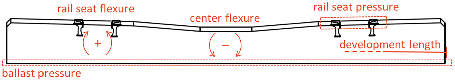
Critical considerations for concrete crosstie design.
Considering flexure, North American prestressed crossties are typically designed in accordance with the recommendations of American Concrete Institute’s (ACI) Committee 318 for Class U (uncracked) members ( 20 ). Thus, their flexural capacity is set to avoid cracking in service conditions. This generally conforms to the recommendations of the American Railway Engineering and Maintenance-of-Way Association (AREMA), which assumes that concrete crossties are designed so that eventual cracks will be shallow enough not to penetrate to the first layer of prestressing tendons from the crosstie’s tensile surface ( 21 ). The two locations on the crosstie that are most critical to flexural design are the rail seat and center. The design is typically governed by center negative and rail seat positive bending moments (Figure 1). The evaluation of stresses and strains in the design process is often based on the Euler–Bernouli beam theory for small deformations ( 22 ).
To prevent cracking, the total stresses at the extreme tensile fiber cannot exceed the concrete modulus of rupture (

where
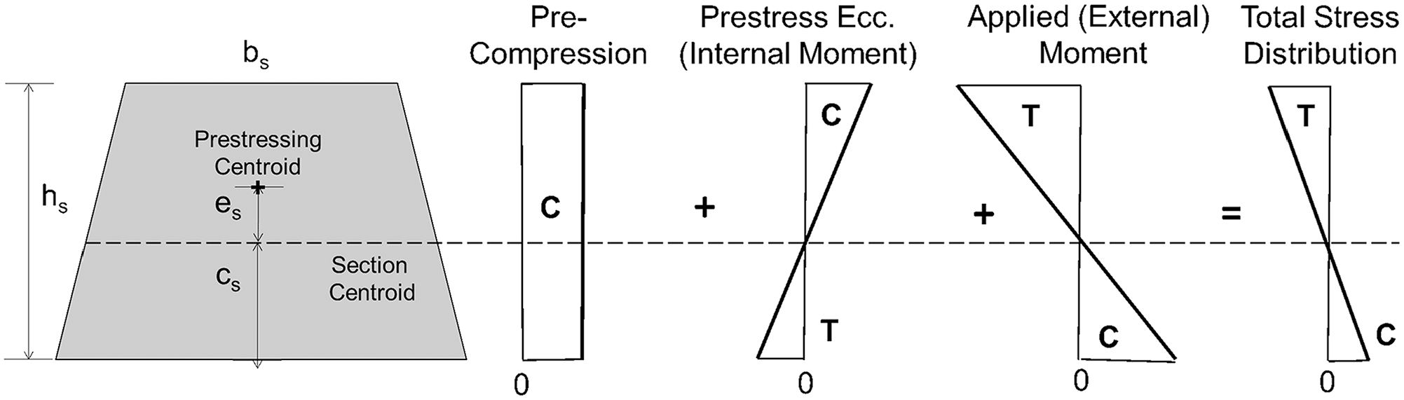
Representation of stresses within a crosstie center cross-section when an external moment causes tensile forces in the top surface.
The discussion in the previous paragraph was related to the calculation of first crack, and concrete was in the linear elastic range of expected behavior of prestressed concrete. However, the ultimate strength and curvature is also of interest in prestress design. The estimation of these parameters is undertaken either by use of an approximate formula or through a procedure referred to as strain compatibility that provides a more accurate estimate of the flexural capacity of the member. Both of these options are referenced in ACI 318-19 ( 20 ).
There are other factors to consider, including stresses at the end section at transfer of prestress and the selection of concrete materials. If unchecked, these could lead to problems such as end-splitting or premature concrete degradation, such as rail seat deterioration or decay owing to alkali–aggregate reactions. Stresses at the ends of crossties (at transfer of prestress) are typically accommodated by ensuring that the concrete reaches a specified “release strength” before transferring prestressing forces to the concrete, typically around 70% of
Typical Flexural Demand and Capacity
The flexural demands and capacity of crossties can vary significantly based on the loading environment they are placed in. Although there has been much research on quantifying typical wheel loads in freight and passenger service ( 8 , 23 , 24 ), these are not direct representations of the flexural demand placed on crossties. First, the wheel loads directly over a crosstie are also partially supported by neighboring crossties, so a load reduction factor is needed, typically around 50% ( 21 ). Second, the actual flexural demand will also be subject to support conditions underneath the crosstie ( 25 ), and even to thermal effects ( 26 ).
Instead of inferring flexural demand from wheel loads and assumed support conditions, an effective way of measuring the demand placed on crossties is to apply surface strain gages on key cross-sections of crossties ( 27 ). This methodology has been applied in some locations in North America and the results have been summarized alongside with published results of first crack and ultimate capacity of concrete crossties (Table 1). For both rail seat positive and center negative bending, it is common to have crossties with ultimate flexural capacity much greater than actual field loads. Bending demand is becoming increasingly predictable for crossties ( 24 , 25 , 27 – 29 ), thereby enabling more cost-effective designs with less reserve capacity ( 6 , 23 , 30 ).
Typical Center Negative (C-) and Rail Seat Positive (RS+) Bending Loads and Capacity in North America, kN·m (kip-in)
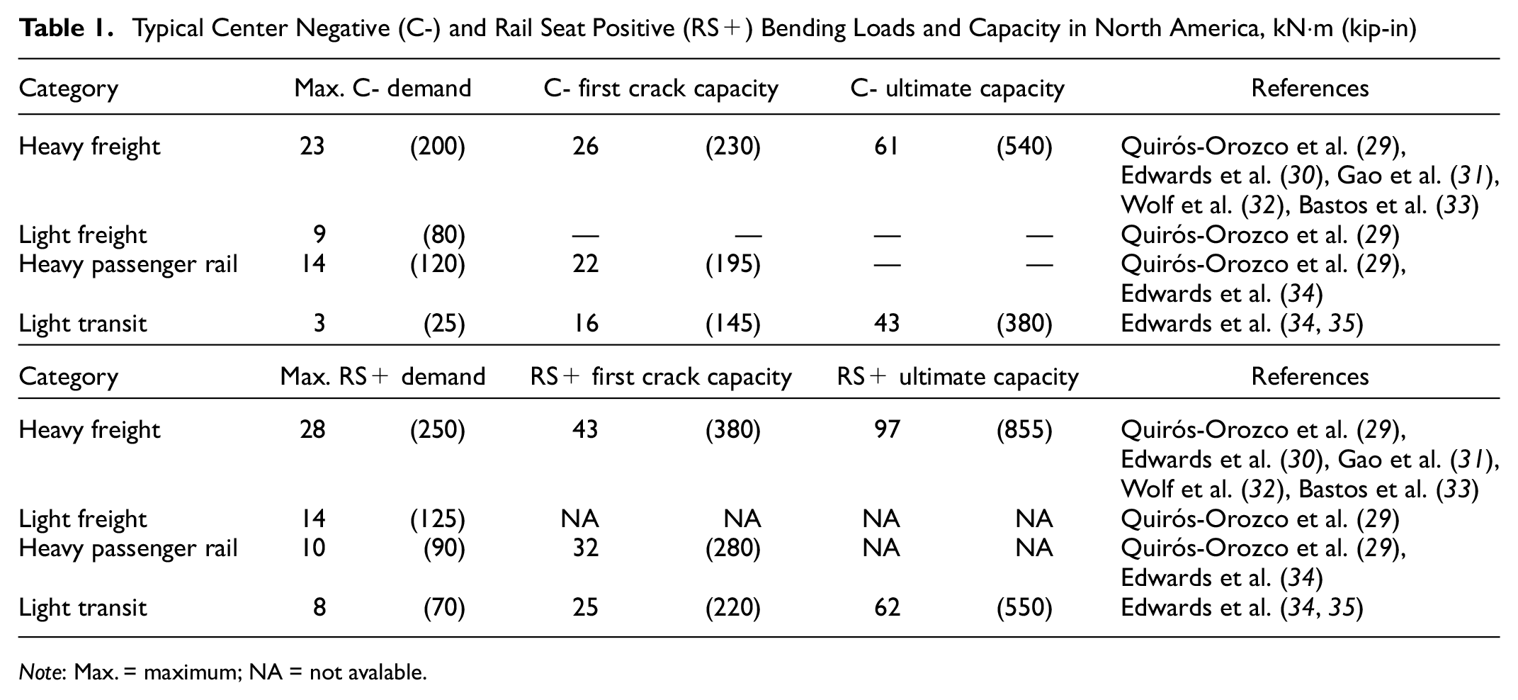
Note: Max. = maximum; NA = not avalable.
Common Failure Modes
Concrete crosstie failure can be related to chemical or mechanical mechanisms ( 36 – 44 ). The most common chemical mechanisms are alkali–silica reaction (ASR) and delayed ettringite formation (DEF). ASR produces an expansive gel and induces internal cracking. It may happen in concrete with reactive aggregates and high-alkali cements, as observed in Amtrak’s Northeast Corridor ( 45 ) and in older Canadian National crossties ( 46 ). DEF may also induce cracking, and its occurrence is closely related to the prevalence of high temperatures in the curing process, although it may happen in lower temperatures in specific cases ( 47 , 48 ). While not frequent, DEF has been observed in crossties worldwide ( 49 – 51 ).
Considering mechanical failures, center binding (negative bending at its center) and abrasion of the crosstie bottom can lead to center cracking ( 25 , 52 – 54 ). Eventually, these cracks can grow owing to interaction with moisture and fines ( 55 ) and may cause catastrophic failures in extreme cases ( 56 ). Rail seat deterioration (RSD) has also been a major failure mode in North America ( 40 , 57 – 59 ), though not necessarily elsewhere in the world ( 36 ). Two Amtrak derailments caused by RSD demonstrate the consequences of this failure mode ( 60 , 61 ), which can be caused by abrasion, crushing, freeze–thaw cracking, hydraulic-pressure cracking, and hydro-abrasive erosion ( 4 ). Moreover, there have been issues related to undesirable prestressing characteristics that led to the loss of concrete-tendon bond and end splitting ( 45 , 62 , 63 ). There have also been reports of freeze–thaw damage and poor air voids distribution ( 64 ), and dynamic response distress ( 65 , 66 ). Railroads, manufacturers, and researchers have ranked the criticality of concrete crosstie failures ( 36 ) (Table 2), showing that the prevalent ones in North America are RSD and shoulder/fastening system wear or fatigue.
Rank of Problems in Concrete Crosstie Track on a Scale of 1–8, with 8 Being the Most Critical
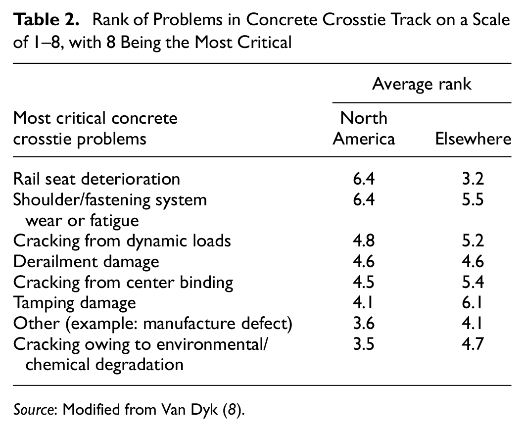
Source: Modified from Van Dyk ( 8 ).
Advancements in Design Philosophy and Methodology
This section of the paper is devoted to the crosstie design philosophy advancements that are being motivated by the pursuit of greater efficiency, higher accuracy, or innovation of the crosstie’s purposes. Advancements targeting failure modes will be reviewed later.
Accounting for Support Conditions and Stress Distribuition in Crosstie Design
Support conditions play a major role in the response of the track superstructure, and much research has been devoted to quantifying such role. Gao et al. ( 31 ) addressed this by developing a support condition back-calculator based on readings from crosstie-mounted surface strain gages, after pilot studies attempted to quantify the effect of varied support conditions on crosstie bending ( 67 ). Instead of relying on crosstie strain data, however, an alternative crosstie support condition estimation method has been developed relying on rail-mounted strain gages ( 68 , 69 ). Yet another method to predict crosstie support conditions is based on ballast particle accelerations and deep residual neural network algorithms, which resulted in 92% accuracy for predictions of fully supported crossties in laboratory experiments ( 70 ). Field research aimed at quantifying variability of support conditions conducted by the Association of American Railroads (AAR) found a wide range of pressures beneath adjacent crossties based on data from matrix based tactile surface sensors attached to the bottom of crossties ( 71 ). Laboratory experimentation on other crosstie materials found similar variability ( 72 ). This is relevant given that small changes in support beneath the crosstie can have disproportionate effects on the bending moments, especially at the crosstie center ( 25 ). Quirós-Orozco ( 73 ) showed that wheel loads and crosstie bending moments are rarely linearly related owing to load-induced ballast redistribution below crossties. Wolf ( 74 ) developed equations (Equation 2 and Equation 3) to calculate support condition-specific maximum bending based on analytical work, which were adopted by AREMA ( 11 ). The first (Equation 2) is used to calculate maximum rail seat positive bending moments and the second (Equation 3) is used for center negative bending moment calculation. These equations are calculated with a variable center reaction reduction coefficient (α) that ranges from 0.66 to 0.86, depending on crosstie length and assuming a uniformly distributed rail seat load. The equations provide a means of calculating the demand moments. The variables related to loading and support conditions can be depicted graphically (Figure 3).
where MRS+ = rail seat positive bending moment (kip-in); R = design rail seat load (kip); L = crosstie length (in); g = rail center-to-center spacing (in); α = center support factor (-); c = 2g-L = center support section (in); s = rail seat width (in).
where MC- = center negative bending moment (kip-in).
Variables for estimation of design bending moment and support conditions.
Support conditions can also change significantly owing to temperature-induced curl behavior of a concrete crosstie when it is subject to changes in the temperature gradient between its top and bottom surfaces ( 26 ). Canga Ruiz et al. ( 75 ) recommended a correction factor of 1 kip-in/°F (0.203 kN-m/°C) for the design capacity of concrete crosstie.
Moreover, support conditions can affect the distribution of vertical loads to the neutral axis. The distribution angle of compressive stresses can vary from about 20° to 50° depending on the rail seat load and the support condition of a crosstie according to laboratory experimentation results ( 76 ).
Moving from Overly Conservative Designs
As mentioned before, the common design practices for concrete crossties in the U.S. assume that they should be uncracked, prestressed beams ( 21 ). Although this is a common serviceability requirement, it has been shown that the uncertainty of demand loads and support conditions can lead to largely conservative designs with reliability indexes between 7 and 10, much greater than a typical target of 3.5 ( 77 ). This can yield high reserve capacities that may be unnecessary under typical service conditions.
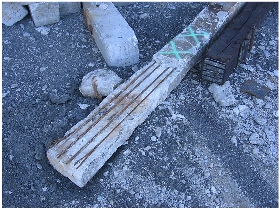
It has been shown that a probabilistic assessment of concrete crosstie failure can lead to more effective and efficient design than the traditional method described previously ( 77 , 78 ). In these studies, the random variables were concrete compressive strength, jacking force, prestressing losses, and center and rail seat field bending moments. Understanding the failure consequences can inform a probabilistic risk assessment of concrete crossties ( 79 ), as these differ from other beams in this regard. Prestressed concrete beams are often safety-critical components within the load path of a structural system and their failure may result in catastrophic results (Figure 4a). Thus, typical designs of prestressed concrete beams are conservative. It is not necessarily beneficial, however, to transfer this conservative design approach to prestressed concrete applications that do not share the same failure consequences, such as railroad crossties (Figure 4b). Attesting to their relatively low failure consequences, the Federal Railroad Administration (FRA) does not consider the failure of one single crosstie to be a violation of their Track Safety Standards ( 80 ). Instead, FRA regulations allow a maximum number of failed concrete crossties within a given length of track for each class of track (a proxy for maximum authorized train speed) (49 CFR 213.109, 2011).
Different consequences of prestressed beam failure example: (a) failed bridge girder and (b) failed crosstie.
Interestingly, however, the expected service life of a concrete crosstie is between 40 and 50 years in North America ( 46 ), a relatively short period if compared with other pretensioned beams, such as those used in bridges (typically designed for over 75 years of service). This shows that the reserve flexural capacity of crossties does not necessarily imply in longer service life. In fact, a crosstie that is no longer fit for service often has not failed in flexure, but has instead failed according to FRA standards. According to the FRA, concrete crossties can be considered to have failed if they have at least one of six characteristics listed within the standards, such as being “configured with less than two fasteners on the same rail” or “abraded at any point under the rail seat to a depth of ½ in.” (12.7 mm) ( 80 ). Therefore, a concrete crosstie is often removed from track owing to failure modes that are not related to structural capacity, but other serviceability criteria.
In addition, railroads that use concrete crossties do not always have a comprehensive understanding of their reserve structural capacity, often leading to their premature replacement. This is the case when crossties with eventual flexural cracks are replaced even if they meet all the FRA requirements within the Track Safety Standards. Derailments on concrete crosstie track have alarmed public safety and regulatory agencies ( 56 , 60 ), contributing to both overdesign and premature component replacement ( 82 ). Properly understanding failure of prestressed concrete crossties is essential for an economical and reliable approach to the design, manufacturing, and use of these components. On this topic, Edwards ( 6 ) provided a means of quantifying the reserve capacity of existing designs and developed a probabilistic framework for future mechanistic–empirical design methods of concrete crossties.
Although less frequent in the railway domain, the concept of mechanistic–empirical design has been applied to highway pavements using probabilistic and performance-based information ( 83 – 88 ). The mechanistic–empirical pavement design guide (MEPDG) ( 87 ) was developed to identify the causes of stress in pavement structures and to map these to observed performance ( 88 ). The mechanistic–empirical concept can be summarized in the following broad steps: inputs, structural response, performance prediction, and failure criteria.
Initial suggestions for the application of a mechanistic–empirical design approach in the rail domain were documented by Csenge et al. ( 89 ) and Van Dyk et al. ( 90 ) and further developed by Quirós-Orozco( 73 ) and Edwards et al. ( 91 ). To achieve this objective, it is necessary to integrate material, component, and system level research, and improve the current understanding of the structural response and degradation of concrete crossties. Edwards et al. ( 91 ) proposed a framework for mechanistic–empirical design of railway track and its components (Figure 5), which considers design optimization in addition to simple feasibility.
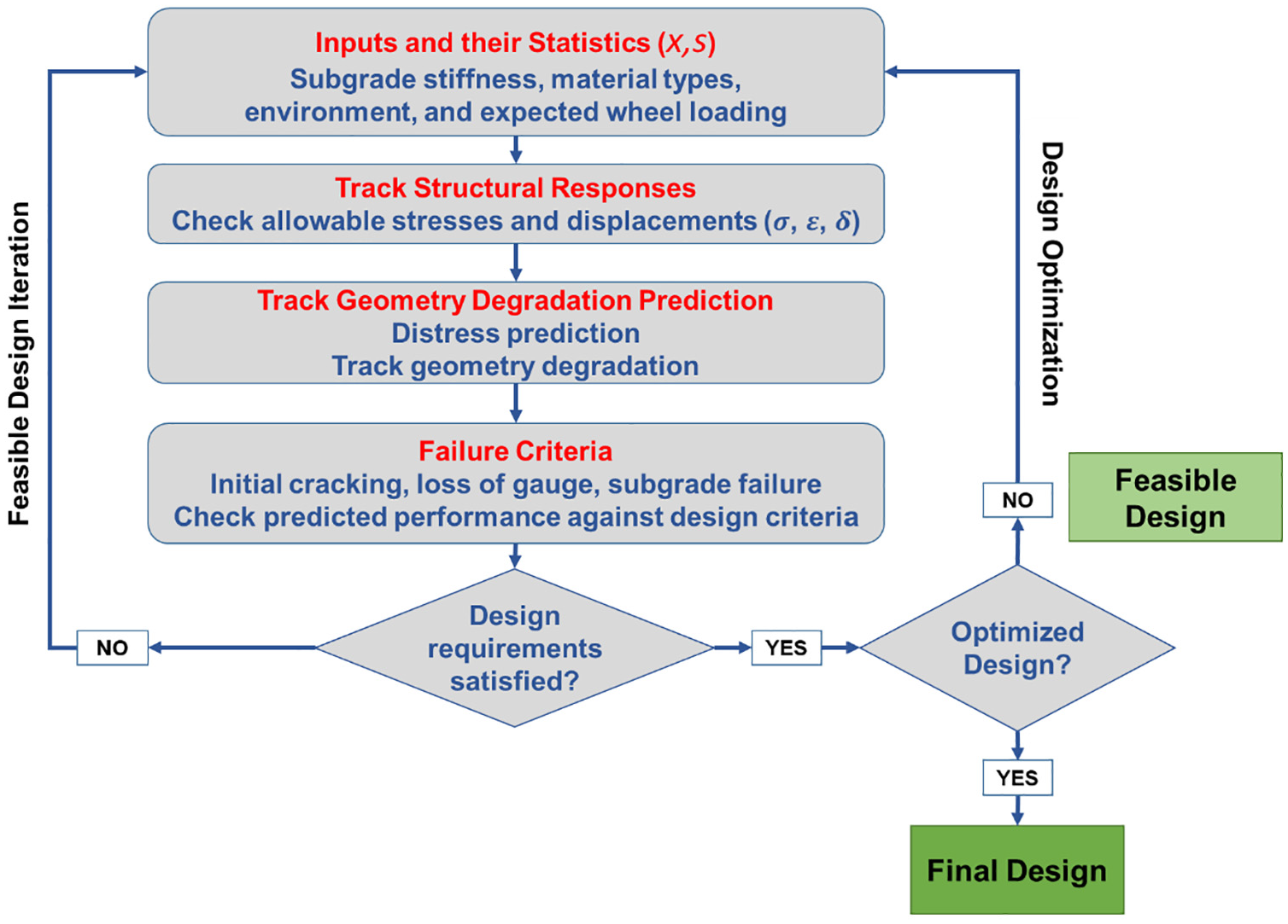
Proposed framework for application of mechanistic–empirical design to railroad track infrastructure.
Analogous to the highway pavement applications, quantifying loads, stresses, strains, and bending moments within the track structure is the “mechanistic” component, and equating these values to the expected long-term field performance currently requires an “empirical” element to the design process that accounts for deterioration rates. There has been much progress in the mechanistic portion of mechanistic–empirical design for railway infrastructure, including results from extensive concrete crosstie research efforts ( 67 , 92 – 94 ), but the empirical portion is more challenging to address, and requires further research. Different from pavements, historical data is not yet readily available to estimate deterioration rates for concrete crossties.
To date, most track design processes do not consider the effects of repeated load application and life cycle estimation ( 2 , 3 ). There are, however, interim steps to implementing time and tonnage into a mechanistic–empirical design process. One such step is to use the literature that quantifies long-term performance and deterioration curves. Track geometry deterioration rates and other indicators could be used as a proxy for component deterioration rates. Examples include research by Zeta-Tech ( 46 ) related to timber crosstie track and research by Lovett ( 95 ) related to the life cycle of track and maintenance prioritization.
Designing Crossties for Innovative Purposes
Many practitioners and researchers have added value to concrete crossties, which go beyond the traditional roles “to support the rails under load, distribute the stresses at the rail seat to acceptable levels for the ballast layer, and, along with the ballast and subgrade, maintain proper geometry of the track structure” ( 4 ). One such innovation is to design crossties targeting a particular range of track stiffness. Given that most of the North American rail network was originally built with wood crossties, concrete crossties can only be adopted in major line renewals or new construction because interspersing wood with concrete can generate undesirable dynamics and uneven load bearing across crossties ( 96 , 97 ). To support incremental conversion from timber to concrete, interspersed engineered concrete crossties that share the same track stiffness as timber crossties have been designed and validated in track ( 98 ).
Worldwide, there has also been an increase of ‘smart’ crossties, which may feature data measurement, energy harvesting, and self-healing ( 99 ). Data measuring crossties may have internal or surface strain gages ( 27 ), fiber optic sensors ( 100 ), Fiber Bragg Gratings, and others ( 99 ). Energy harvesting crossties have also been produced by attaching solar panels with a recycled rubber tire coating, with a focus on durability and environmental sustainability ( 99 , 101 ). More broadly, Edwards et al. ( 102 ) provided a roadmap for sustainable smart track focused on wireless continuous monitoring of railway track condition. Self-healing crossties are envisioned future developments ( 99 ) using self-healing cement concrete composites ( 103 ).
Advancements in Addressing Failure Modes
Design changes in concrete crossties often aim to mitigate failure. This section summarizes advancements targeting specific failure modes. While most solutions are design related, some involve manufacturing, maintenance, or testing processes.
Cracking Mitigation with Low-Modulus Aggregate and Fiber Reinforcement
Researchers have explored ways to mitigate concrete crosstie cracking. One solution is adding fibers to the concrete mix. Shin et al. ( 104 , 105 ) showed that steel fiber-reinforced crossties had increased flexural capacity, toughness, less crack propagation, and reduced spalling. This aligns with findings from Sadeghi et al. ( 106 ) and Yang et al. ( 107 ), who also reported improved performance with steel fibers. Similar results are expected with synthetic fibers ( 108 ). Master ( 109 ) found that polypropylene fiber-reinforced crossties performed better than baseline crossties relating to cracking and spalling (Figure 6).

Baseline and fiber-reinforced concrete crossties at ultimate failure.
An advancement in mitigating crosstie cracking is the use of low-modulus aggregate as a substitute for coarse aggregate, producing “high-strength reduced-modulus” (HSRM) concrete crossties ( 110 , 111 ). These less-rigid crossties experience lower stresses, delay crack initiation, and favor more shallow cracks over deeper ones compared with conventional crossties (Figure 7) ( 110 , 111 ). They also exhibit superior post-cracking performance under high amplitude cyclic load.
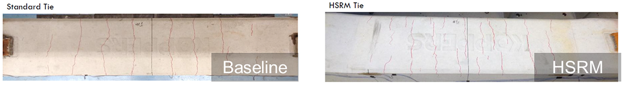
Baseline and high-strength reduced-modulus (HSRM) concrete crosstie flexural cracks under same loading conditions.
Preventing End Splitting
Substantial research has been conducted to prevent end-splitting of concrete crossties in Amtrak’s Northeast Corridor ( 45 ). Researchers found that the indentation pattern of prestressing tendons significantly affects bond-slip and end-splitting ( 112 – 114 ). A wire indent profiling system was developed to assess bond and splitting propensity ( 115 ). A test has been developed (ASTM A1096) to determine bond quality for both individual wire and seven-wire strand ( 116 , 117 ). Transfer length depends on concrete strength at de-tensioning ( 118 ). Savić et al. ( 119 ), suggest increasing concrete cover and reducing wire indent depth to prevent end-splitting. Prestressing force also affects bursting stresses ( 120 – 122 ). Moreover, highly angular coarse aggregates can reduce end cracks ( 123 ).
In 2021, the AREMA Manual for Railway Engineering included a design validation test for evaluating the splitting resistance of new crosstie designs ( 21 ). The test involves fabricating pretensioned prisms or full-size crossties with reduced concrete cover, which are inspected for splitting cracks 14 days after de-tensioning. Thus, successful designs will have an inherent safety factor against splitting ( 124 ).
Increasing Resistance to Freeze–Thaw Cycles with Controlled Vibration
Freezing and thawing damage in concrete often relates to inadequate air voids in the matrix. Albahttiti et al. ( 125 ) found that manufacturing can reduce air content in fresh mixtures. Without equivalent vibration, fresh concrete samples often have more air than the final product, complicating quality assurance. Riding et al. ( 126 ) noted variability in vibration methods and concrete mix among manufacturers, making standard tests more complex. Song et al. ( 127 ) proposed a performance-based procedure using table vibrators matching the crosstie vibration frequency and magnitude. Riding et al. ( 128 ) suggested using rigidly mounted steel forms for external form vibrators and assessing freeze–thaw durability by comparing dynamic modulus before and after testing.
Strategies to Address Rail Seat Deterioration
Researchers have identified mechanisms and consequences of RSD and proposed methods to reduce its occurrences ( 4 , 12 , 59 , 129 ). Kernes et al. ( 129 ) showed that epoxy coatings used in North America can increase abrasion resistance by about 10%. Using cast-in-place steel plates over the rail seat also seems to be a potential solution to RSD ( 39 ). Alternatively, some crossties have been manufactured with a greater rail seat area to reduce contact pressures, and some fastening systems have been engineered to provide greater resiliency and rail restraint, often using multi-layer abrasion resistant pads ( 39 , 130 ). Crosstie abrasion resistance depends on the concrete mix properties, particularly concrete strength and aggregate hardness ( 131 ). Shurpali et al. ( 132 , 133 ) found that adding silica fume, fly ash, steel fibers, metallic fine aggregates, and ensuring moisture during curing improves abrasion resistance. Over the years, industry reports of RSD cases have become less frequent and severe.
Reducing Bottom Abrasion with Resilient Materials
Bottom-abraded crossties are relatively common ( 53 , 134 ) and are often linked to high vertical displacements and center cracks ( 52 , 54 ). After investigating 36 railroad sites of concern, Riding et al. ( 135 ) identified environmental and track factors like drainage issues, high track stiffness, and track transition zones contributing to abrasion. In addition to providing proper drainage and clean ballast, a potential mitigating action is to provide under-tie-pads (UTPs) or under-ballast-mats ( 135 ). UTPs have been proven to effectively mitigate stresses and better distribute loads at the crosstie–ballast interface ( 136 , 137 ).
Post-Tensioning to Improve Rotational Capacity and Potential Bond Problems
Unintentional debonding of pretensioned tendons can lead to longitudinal cracks and reduced flexural performance ( 41 , 79 ). Flexural cracks may precede longitudinal cracks if moisture and fines are present with cyclic opening ( 79 ). Laboratory results suggest post-tensioned crossties are less susceptible to longitudinal cracks than pretensioned ones, as they do not rely on concrete–tendon bond to transfer prestressing forces ( 79 ). When transverse cracks open owing to brief overloads, unbonded post-tensioned crossties exhibit greater deflection than pretensioned ones. This compliance allows them to conform to the ballast without yielding prestressing steel or causing bond-splitting cracks.
Considerations for Future Advancements
In addition to the previously mentioned advancements, the authors also would like to highlight opportunities for further research. These include recent developments that may represent trends for future applications or topics that are still under-explored research needs.
Performance-Based Design and Risk Assessment
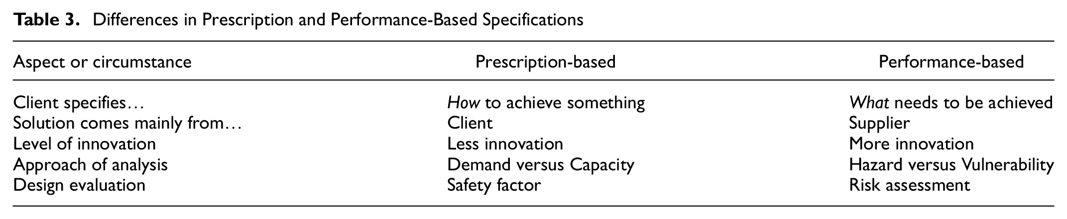
Frequently, concrete crossties are designed following prescription-based specifications, which can limit innovations when compared with performance-based specifications (Table 3). For example, the AREMA recommendations prescribe that “fine and coarse aggregates should be hard strong, durable, and free of deleterious material” ( 21 ). Although this is a subjective statement, it discourages the use of low-modulus aggregate in concrete crossties mentioned earlier. It seems that the crosstie industry would benefit from adopting requirements that are performance-based, as is already happening elsewhere in the concrete industry ( 127 , 138 , 139 ). Performance-based specifications are also better suited for applications that may consider post-cracking and post-failure behavior, including risk analysis, which is an important step in reducing the reserve capacity of concrete crossties.
Differences in Prescription and Performance-Based Specifications
These topics are often closely related to the new design philosophies mentioned previously. For instance, Edwards ( 6 ) developed a process using structural reliability analysis to optimize new designs by comparing target reliability indices (β) with existing designs. The new designs were more economical, with a 50% reduction in center negative moment capacity for heavy rail transit and a 40% reduction in rail seat bending capacity for HAL freight. This exemplifies that performance-based designs can lead to solutions that are not overly conservative but are both economical and structurally sound.
Using Non-Contacting Measuring Systems
The most common tests for concrete crosstie qualification or quality control in North America are the flexural tests recommended by AREMA ( 21 ), which are based on the maximum length of cracks under load with visual inspection using a magnifying glass. In such an approach, the actual strain fields, full cracking pattern and transfer length are neglected.
Production plants, however, are improving in their assessment of the actual transfer length of manufactured crossties. Kansas State University researchers have developed different non-contact transfer length measurement devices, established statistical algorithms to automatically extract transfer lengths from crossties with non-prismatic cross-sections by establishing the shape factor, and measured over 1,000 transfer lengths of actual crossties in production ( 13 , 140 , 141 ). Digital image correlation (DIC) (Figure 8) techniques ( 142 ) are also being developed to work as a non-contact alternative for product qualification ( 143 , 144 ), as well as for mapping flexural behavior and measuring transfer length of concrete crossties ( 145 ) in production lines. In Europe, researchers have added acoustic emission to DIC to better map cracks and understand their damage source in structural concrete in service ( 146 ).
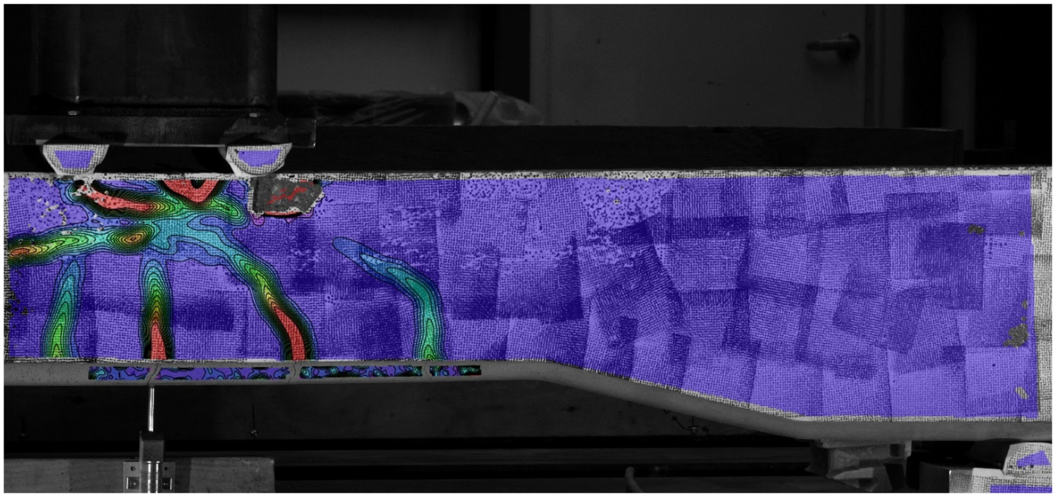
Cracking map of section of concrete crosstie under flexural testing produced with digital image correlation (DIC) (test is performed with crosstie upside down).
Non-contact field inspection tools are also being developed. There are commercially available machine vision and Light Detection and Ranging (LiDAR) systems that are backed by artificial intelligence and can assess and rate the state of good repair of concrete crossties. Sonic and ultrasonic concrete crosstie inspection techniques have also emerged. In partnership with the FRA, researcher Fisk led the development of an inspection apparatus that assessed the internal condition of in-service concrete crossties using sonic/ ultrasonic impact velocity and echo measurements ( 147 ). Although the measurements of this apparatus were non-contact, the energy impact source touched each crosstie to generate inspection pulses. More recently, Evani et al. ( 148 ) proposed a fully non-contact system for air-coupled ultrasonic assessment of concrete crossties.
Hybrid Crossties: Simultaneously Post and Pretensioned
Hybrid crossties may represent an opportunity to explore the advantages of both post and pretensioned systems simultaneously. While unbonded post-tensioned crossties do not have bond-related problems, pretensioned ones tend to have smaller, less-severe cracks, and have an inherent corrosion resistance provided by the bonded concrete. Given that bond issues are more closely related to rail seat flexure owing to its proximity to the crosstie’s end, it seems that post-tensioned, wrapped tendons are ideally suited to resist rail seat moments. Nevertheless, pretensioned tendons may still be desirable to control center cracking and to prevent moisture ingress and corrosion.
Smart Crossties
Jing et al. ( 99 ) proposes that future advancements of smart concrete crossties are expected to be linked to three technologies: (i) intrinsic self-sensing composite crossties (crossties with sensing components in the concrete matrix, such as carbon nanotubes or carbon fibers); (ii) self-healing concrete crossties; or (iii) internet of things (crossties that process and wirelessly transmit data from its sensors). They also suggest that such crossties be used for maintenance prioritization or for monitoring in targeted zones ( 99 ). All these advancements are somehow connected to assessing the condition of part of the railway infrastructure or minimizing its degradation. Beyond such applications, some previously mentioned examples show that there are opportunities that may not be directly related to the state of good repair of the track and its components. When considering environmental concerns, smart crossties future advancements could be related to harvesting solar energy or using eco-cement and an engineered porous structure to contribute to sequestration of carbon dioxide (CO2) at a faster rate than regular concrete carbonation.
Instrumented crossties (and other track components) can also provide railroads with relevant information to trigger maintenance activities. Qian et al. ( 149 ) introduced the Railroad Infrastructure 4.0 concept of railroad track maintenance prioritization and management based on the four pillars of sensor monitoring, cloud computing, decision making, and problem solving. They demonstrated this concept using strain-gage-mounted concrete crossties to generate back-calculated support conditions and ballast pressures, ensuring that well-informed maintenance decisions could be made considering track tamping intervals.
Another example is the tracking of crosstie movements. Gao et al. ( 150 ) integrated a gyroscope, an accelerometer, and a magnetometer into crossties. This allowed them to fully characterize translation, rotation, and vibration movements, enabling the assessment of track quality and the risk of accelerated track component deterioration. In addition, Siahkouhi et al. ( 151 ) added carbon nanotubes (CNTs) to the concrete, creating smart CNT self-sensing concrete crossties that can identify hanging crossties in regions lacking ballast support.
Considerations on Additional Requirements
Amtrak’s experience with crosstie splitting failures may suggest that it is better to avoid interference of the fastening system shoulder location with the lines of the tendons (Figure 9). It seems that future designs should not just ensure that the shoulder depth is not aligned with the tendons, but also ensure that the shoulder termination points are not toward the tendon lines. This could mitigate the risk of longitudinal cracking disturbing the integrity of the shoulder.
Splitting failure leading to removal of fastening system shoulder.
Still considering design, camber allowances perhaps could be less be prescriptive and more adapted to in-service conditions. AREMA recommends that “vertical camber in the ties measured 28-days after manufacture should not exceed 1/1,000 of the tie length.” ( 21 ). There is an opportunity to consider support conditions and tamping effects on what could be an acceptable concrete crosstie camber.
Conclusions
This paper summarizes recent advancements and identifies trends for the future design and use of railway concrete crossties in North America. From design to failure modes, there has been substantial progress in the last 12 years. New designs are factoring in support conditions and safety against splitting, as well as transitioning toward mechanistic–empirical methods that adopt performance-based criteria. Moreover, the industry has managed to reduce the frequency and severity of RSD cases, which used to be the most critical issue related to concrete crossties. Moreover, the amount of research and development related to understanding bond and splitting failures are producing lasting benefits and have already affected the AREMA manual. Future advancements are likely to be related to more effective quality control procedures, possibly using laser-speckle or DIC techniques in production lines.
Further advancement in design approaches will likely be linked to the understanding of failure modes and the risk associated with them, but the implementation of these advancements may require the industry (AREMA) and the government (FRA) to update their definitions of concrete crosstie failure. Unconventional uses of concrete crossties may also continue to rise, especially with the rapid technological advancements of sensors and internet of things. In addition, it is possible that crossties that can foster sustainability will have their use increased by railroads, especially those under environmental, social, and corporate governance (ESG).
Footnotes
Acknowledgements
This research effort is funded by the Federal Railroad Administration (FRA), part of the United States Department of Transportation (U.S. DOT). The authors also would like to acknowledge the following industry partners for supplying insight, recommendations, and materials to this study: BNSF, Union Pacific, Norfolk Southern, and the U.S. DOT Volpe Center. J. Riley Edwards has been supported in part by the grants to the Illinois Rail Transportation and Engineering Center (RailTEC) from CN and Hanson Professional Services.
Author Contribution
The authors confirm contribution to the paper as follows: study conception and design: J. Bastos, R. Edwards, M. Dersch, D. Rizos, Y. Qian, and R. Peterman; data collection: J. Bastos; analysis and interpretation of results: J. Bastos, R. Edwards, M. Dersch, D. Rizos, Y. Qian, and R. Peterman; draft manuscript preparation: J. Bastos, R. Edwards, and M. Dersch . All authors reviewed the results and approved the final version of the manuscript.
Declaration of Conflicting Interests
The authors declared no potential conflicts of interest with respect to the research, authorship, and/or publication of this article.
Funding
The authors disclosed receipt of the following financial support for the research, authorship, and/or publication of this article: This research effort is funded by the Federal Railroad Administration (FRA), part of the United States Department of Transportation (U.S. DOT) (grant number 693JJ621C000009).
Data Accessibility Statement
Data sharing is not applicable to this article as no new data were created or analyzed in this study.
The material in this paper represents the position of the authors and not necessarily that of sponsors.