
Abstract
The shear strength of corrugated steel web with encased concrete is not clear yet. Initially, to study the shear behavior of corrugated steel plate encased with concrete, model tests of straight steel plate and corrugated steel plate encased with concrete were carried out. At the same time, tests of steel plate without concrete encasement were carried out to compare with the concrete encasement model. The shear mechanism of corrugated steel plate encased with concrete is presented. The concrete compression strut and corrugated steel tension strut constitute the “X” truss to provide the shear bearing capacity. The ratio of load shared by concrete and corrugated steel plate is studied at the elastic stage. The shear strength model of the corrugated steel plate with concrete encasement is presented and verified. Finally, shear demand and shear strength of a real bridge are calculated based on the finite element model and the presented strength model. Research results show that Qishan River bridge in China has a safe shear design of a cross-section with a corrugated steel web encased with concrete.
Many concrete girder bridges with corrugated steel webs (Figure 1) have been constructed around the world ( 1 ). Cognac bridge, in France, built in 1986, was the world’s first bridge with corrugated steel webs. At present, this type of bridge has been used in the construction of cable-stayed bridges with a span of over 200 m ( 2 ). Torsion capacity, buckling, and natural frequency have been researched recently ( 3 – 6 ). A new type of composite box girder has been introduced with corrugated webs and concrete-filled steel tube slab to overcome cracking on the web and reduce self-weight ( 7 ).
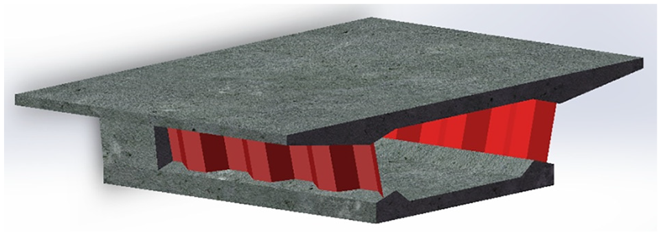
Box-girder with corrugated steel webs.
The shear strength of corrugated steel webs is an important issue in the design of box girder bridges with corrugated steel webs. Easley and McFarland, for the first time, carried out research into shear buckling behavior ( 8 ). From then on, the shear deformation and shear strength of corrugated steel web were researched by many scholars ( 6 , 9 , 10 ).
To improve the structural performance of continuous composite girders under hogging moment, Nakamura and Morishita proposed a kind of partially encased composite I-girder around support parts ( 11 ). Reinforcing bars were welded to the upper and lower flanges, and concrete was poured into the area surrounded by the flanges and web. Bending and shear tests of the composite girders were performed, showing that the bending strength of the partially encased girder model is 2.08 times higher and the shear strength is 2.98 times higher than that of the conventional steel I-girder model. The corrugated steel webs encased with concrete are formed under hogging moment to prevent the buckling of corrugated steel webs. This structure is considered as a mandatory requirement in the design criterion of prestressed concrete (PC) box girder bridges with corrugated steel webs in Japan, but only the shear effect of steel webs was considered for shear strength of the corrugated steel webs encased with concrete ( 12 ). Up to now, little research has been done on the mechanical properties of concrete lined with corrugated steel webs. Wang et al. conducted an experimental study on the flexural performance of concrete lined with corrugated steel web ( 13 ). He et al. carried out experimental research and numerical simulation on the shear performance of concrete lined with corrugated steel webs ( 14 , 15 ).
The mentioned composite girder has been applied to the construction of box girders with corrugated steel web adjacent piers. However, the structural details of the encased concrete dimensions and proportion of load shared by the concrete and corrugated steel plate were still subject to lack of clear regulation because of the delay of corresponding research. The structural design of the concrete encasement is mainly determined by the length and thickness of the encased concrete. The bending behavior of concrete-encased composite girders with corrugated web under two-point symmetric loading was experimentally investigated ( 13 ). Experimental results show that partially encased girder has superior bending strength and ductility compared with steel I-girder, as local buckling of compressive flanges is restricted by concrete encasement. The shear behavior of such partially encased composite I-girders under anti-symmetric loading has been experimentally and analytically investigated. The shear stiffness of the composite section is based on the total summation of corrugated web and concrete encasement with average thickness before cracking ( 14 , 15 ).
To sum up, there are few reports about design specifications for partially encased composite I-girders with corrugated steel web, to the best knowledge of the authors ( 12 ). Furthermore, only a little research has covered the shear performance of corrugated steel plate encased with concrete. The main objectives of the shear tests in this paper are understanding the shear performance of composite I-girders with corrugated steel web, verifying the equivalent stiffness and strength calculation models of composite I-girders with corrugated steel web at the elastic stage, and determining the load carrying capacity of concrete encasement and steel web.
Experimental Program
Test Specimens
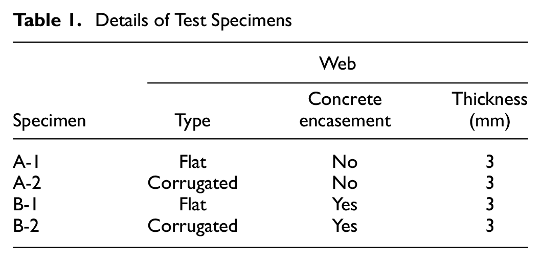
The model test was divided into two groups: steel I-girders (Series A) and steel I-girders with concrete encasement (Series B). The details of the parameters for the test specimens are shown in Table 1.
Details of Test Specimens
The elevation and cross-section view of test specimens (without stud connectors) are shown in Figure 2. The width of horizontal and inclined plates is 99 and 100.8 mm, respectively, the projected width of the inclined plate is 81 mm, and the details of the dimensions for the corrugated web are depicted in Figure 3. Shear studs with a diameter of 6 mm and height of 40 mm were welded on one side of the steel web to connect with the concrete (Figures 4 and 5) ( 16 ).
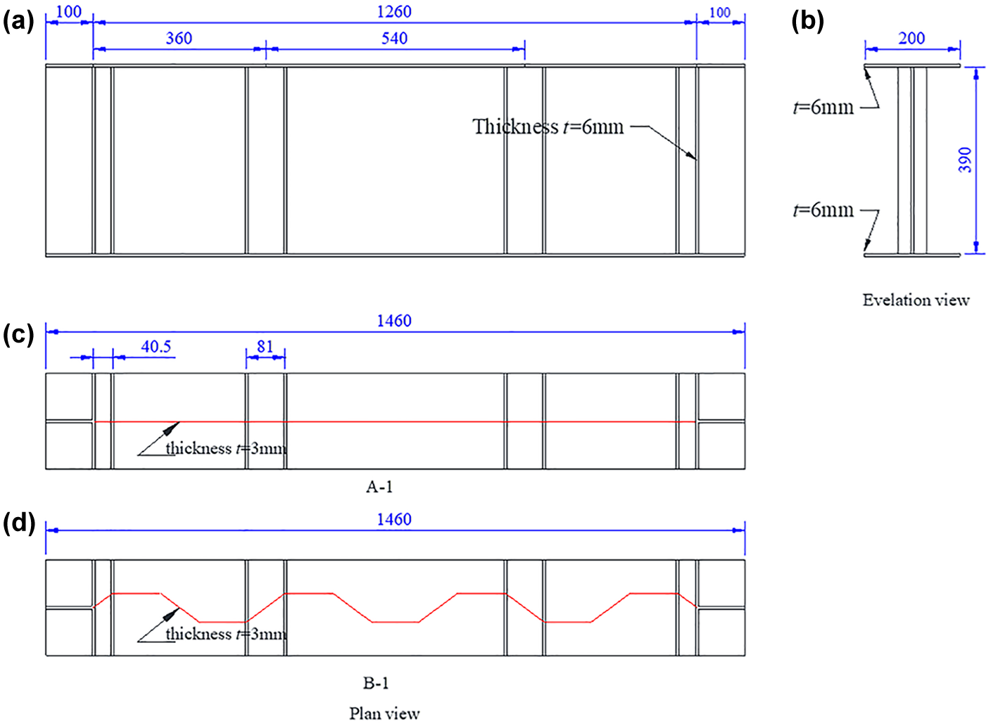
Dimension of test specimens (mm): (a) front view of the specimen, (b) cross-section of the specimen, (c) side view of specimen A-1, and (d) side view of specimen B-1.
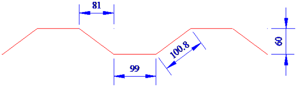
Diagram of corrugated profiles (mm).
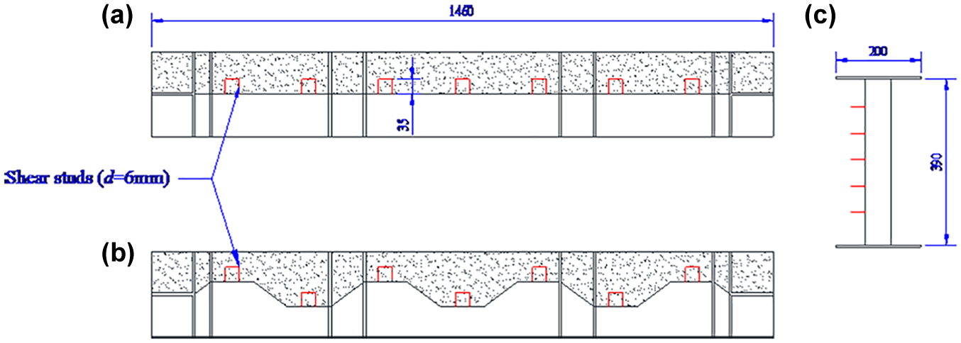
Arrangement of shear studs (mm): (a) arrangement diagram of specimen with flat web, (b) arrangement diagram of specimen with corrugated web, and (c) cross-section of the specimen.
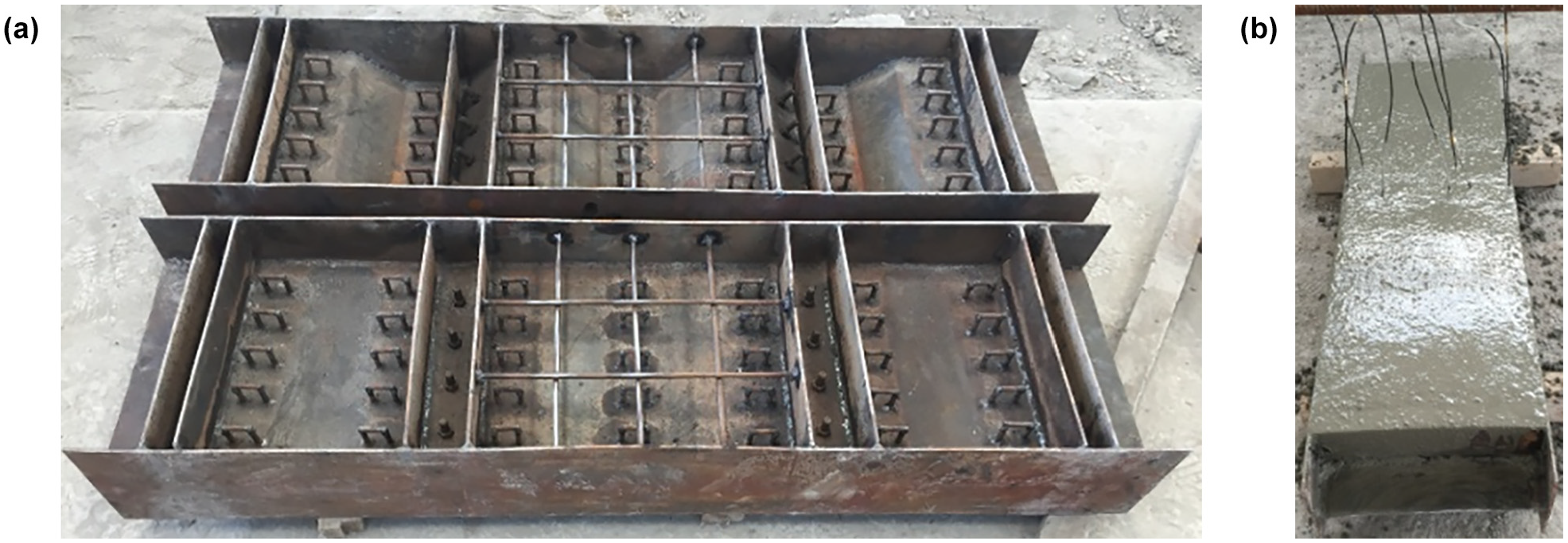
Test specimens: (a) steel structure and (b) concrete casting.
The concrete has a design compressive strength of 50 N/mm2 and Young’s modulus of 34,500 N/mm2. The steel girders are made of steel Q235 with a nominal tensile yielding stress of 235 N/mm2 and Young’s modulus of 200,000 N/mm2.
Loading and Measurements
Static tests of partially encased composite I-girders under shear loading were carried out in the Structure Laboratory of Shandong University. Two concentrate loads were applied by the loading girder at the end of the cantilever part and the middle of the supported rollers (as shown in Figure 6).
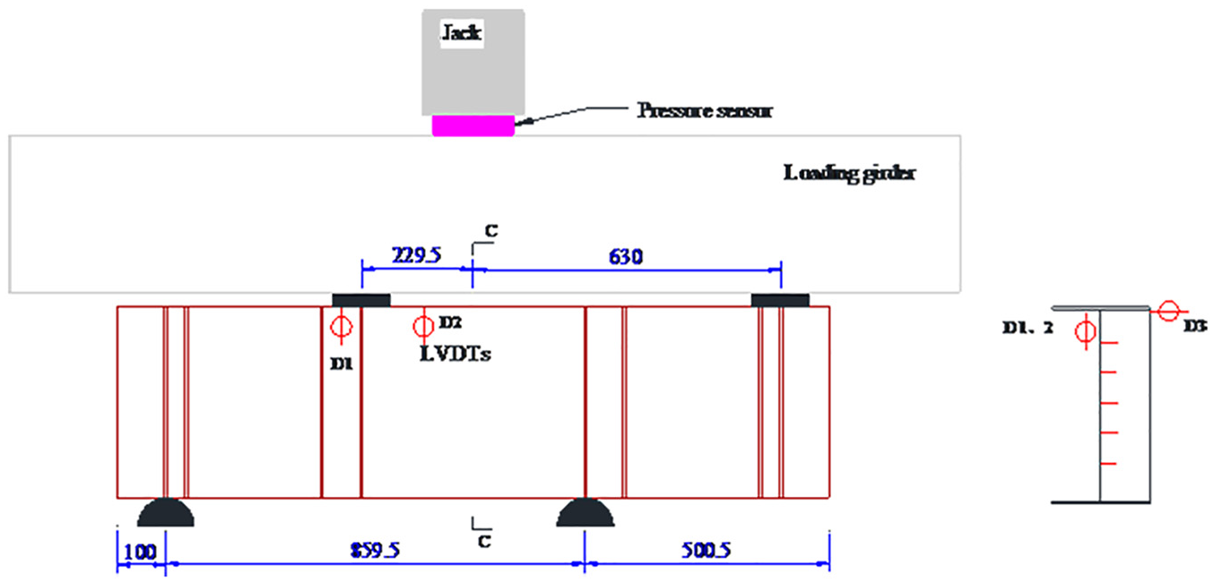
Set-up and arrangement of linear variable differential transformers (LVDTs) (mm).
Displacement transducer linear variable differential transformers were used to measure the vertical deflection and lateral displacements (as shown in Figure 6). At critical sections, such as the middle of shear panel (Section C), the strains were measured using 50 mm electrical gauges for the concrete and 5 mm electrical gauges for the steel web (as shown in Figure 7).
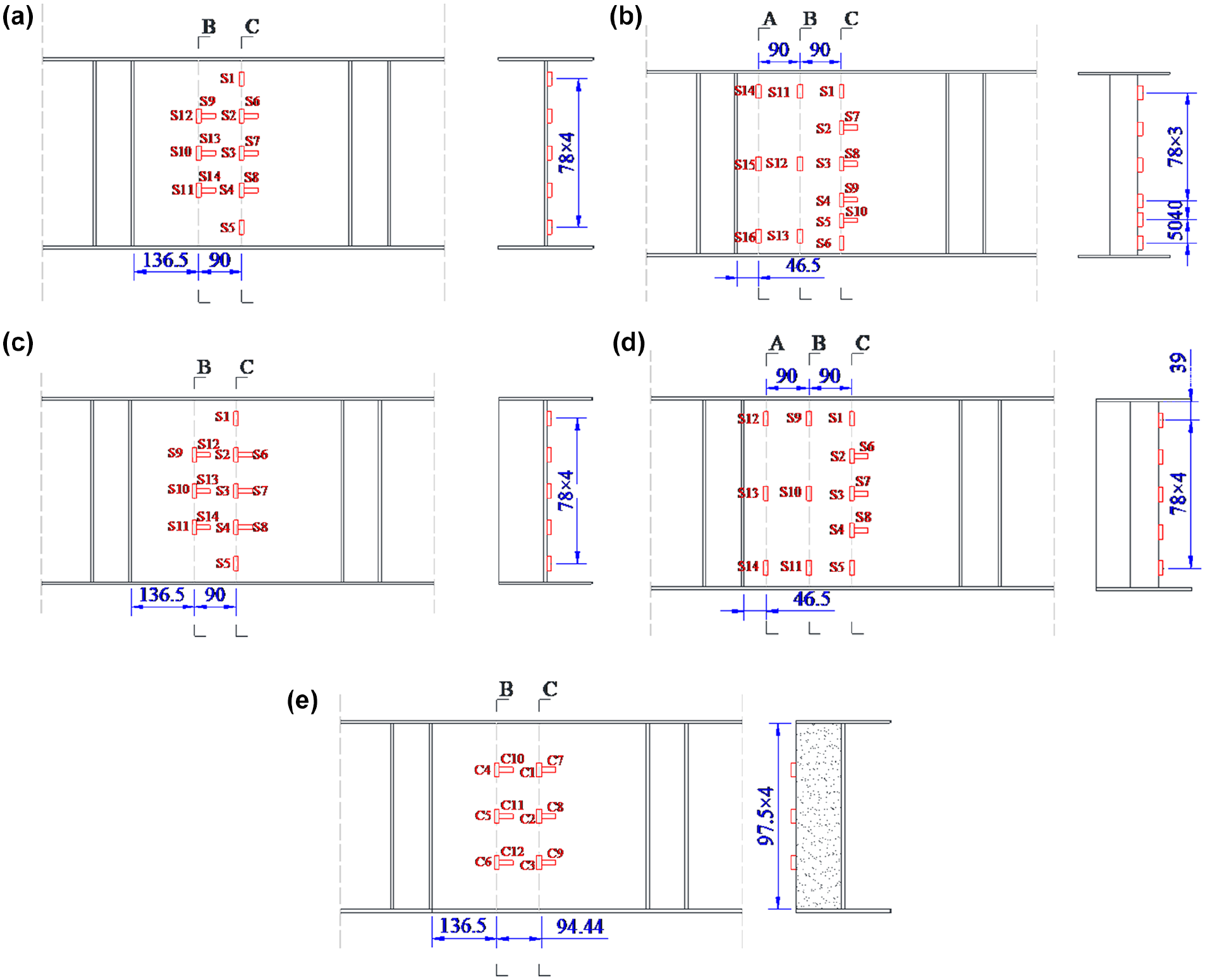
Strain gauges on steel web and concrete (mm): (a) A-1, (b) A-2, (c) steel web of specimen B-1, (d) steel web of specimen B-2, and (e) concrete of specimen B-1 and B-2.
Discussion of Test Results
Failure Mode
The steel web is in an elastic state before yielding, and the specimen can still bear load until the ultimate state, then out-of-plane buckling occurs at the steel web (as shown in Figure 8a and b ) resulting in girder failure. For partially encased composite I-girders, cracks initiate along the diagonal line on the surface of the concrete with load increase, then the steel web yields (as shown in Figure 8c and d ), which increases the width and length of the cracks. Compared with the specimen without the encased concrete, the steel web of specimen B-2 shows local buckling (as shown in Figure 8e). Finally, the concrete crushes near the loading position when the principal compressive stress of the concrete reaches the ultimate strength (as shown in Figure 8f). Figure 8 shows the failure modes of partially encased composite I-girders. There are no evident differences of failure modes between the girders with corrugated web and those with flat web.
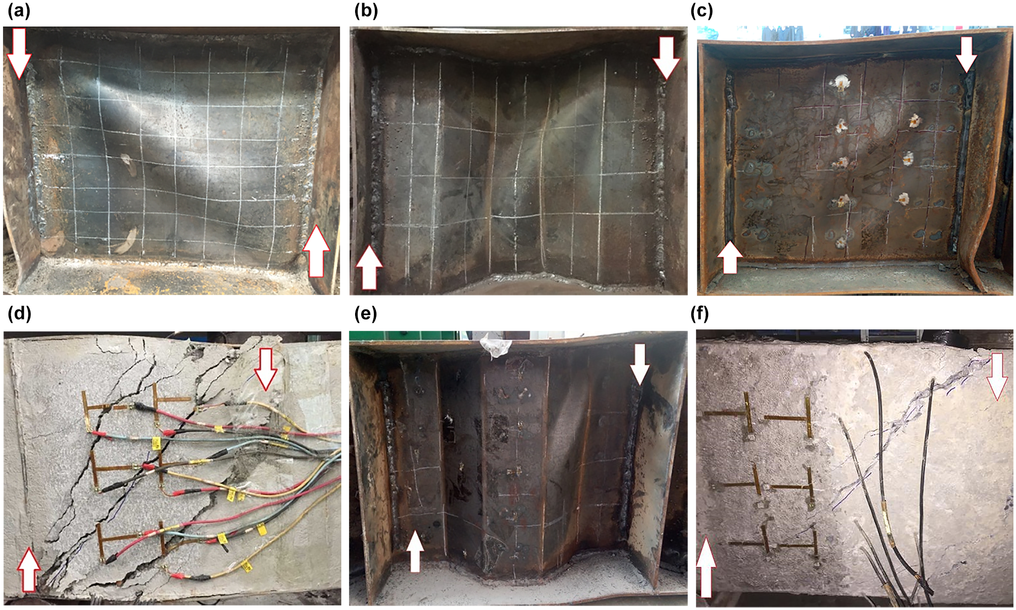
Failure mode of specimens: (a) A-1, (b) A-2, (c) web of specimen B-1, (d) concrete surface of specimen B-1, (e) web of specimen B-2, and (f) concrete surface of specimen B-2.
Load-Deformation Curve
The load-deformation relationship curves are described in Figure 9. The analysis of the characteristic points of the load-displacement curves (as shown in Figure 9a and b ) is listed in Table 2. For specimens without concrete encasement (Series A), the bearing capacity (473 kN) of girder with corrugated web (A-2) is slightly larger than that (423 kN) with flat web (A-1). For specimens with concrete encasement (Series B), the bearing capacity (921 kN) of girder with corrugated web (B-2) is slightly larger than that (820 kN) with flat web (B-1). For girders with flat web, the yield capacity (670 kN) of girder with concrete encasement (B-1) is larger than that without concrete encasement (A-1), and the stiffness and ultimate load follow the same rule. For girders with corrugated web, the yield capacity (785 kN) of girder with concrete encasement (B-2) is larger than that without concrete encasement (A-2), and the stiffness and ultimate load follow the same rule. The lateral deformation (1 mm) of specimens with concrete encasement is smaller than that without concrete encasement (4–5 mm). From the failure of the web, we can find that the typical buckling failure occurs for steel girders, and the lateral deformation of the composite girder is small.
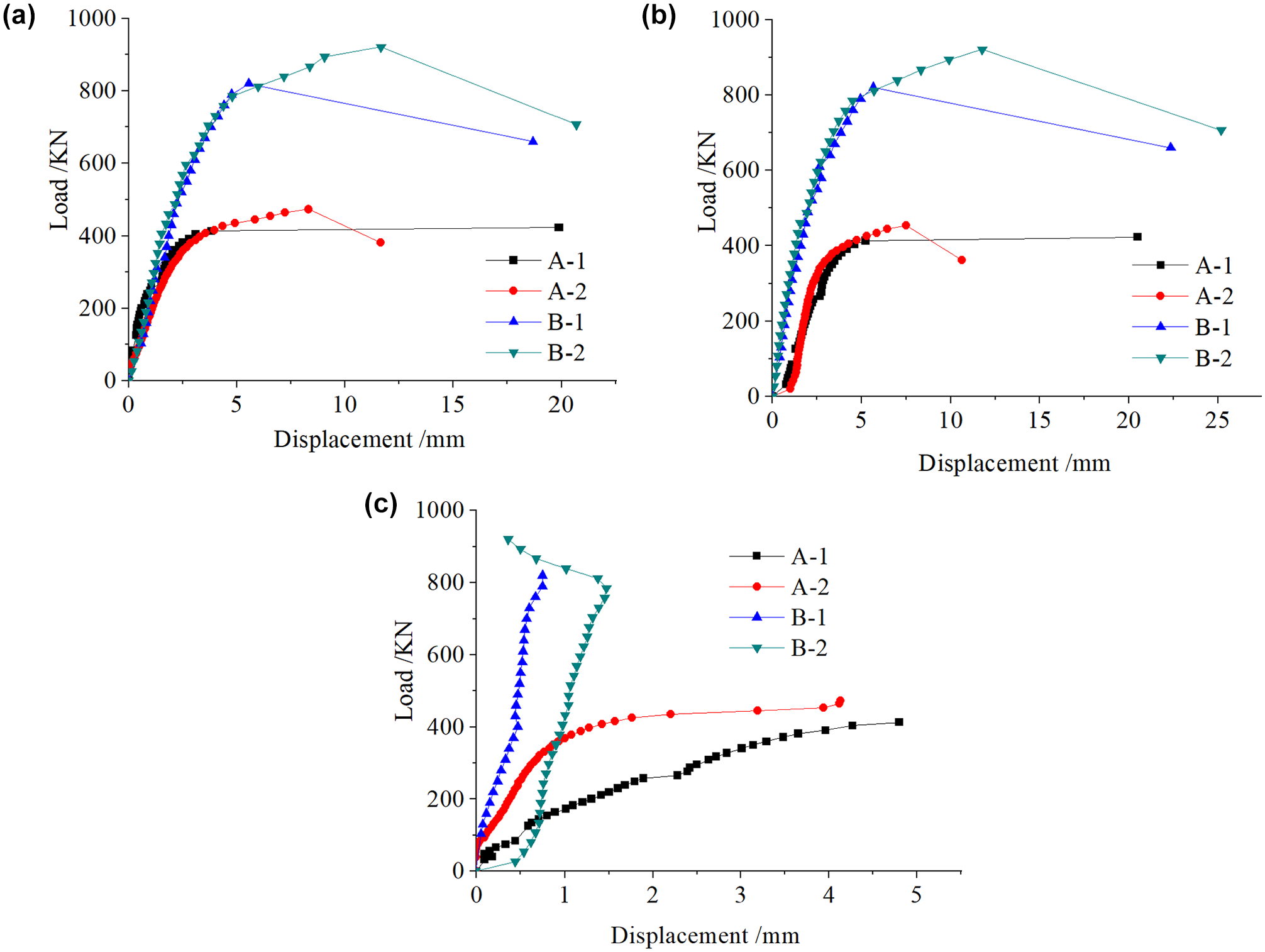
Load-deformation curves: (a) D1, (b) D2, and (c) D3.
Characteristic Point Data of Force-Displacement Curve
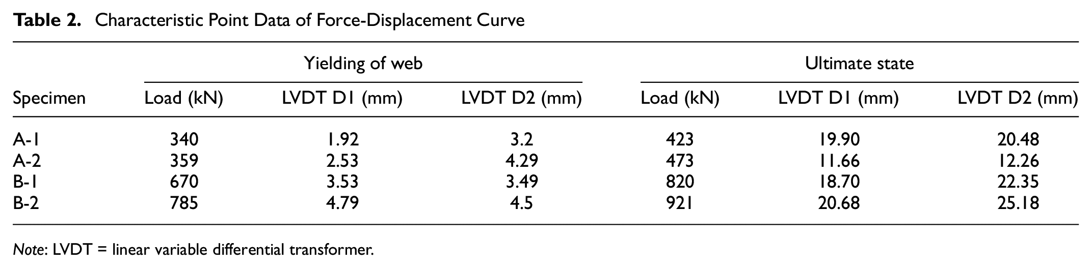
Note: LVDT = linear variable differential transformer.
Load-Strain Curve
Figure 10 shows the load-strain relationship on the steel web and on the concrete. The strains on the web in both vertical and horizontal directions increase almost linearly before the steel yielding. Shear yield occurs in girder with flat web (as shown in Figure 10a and b ), while shear buckling occurs in girder with corrugated web (as shown in Figure 10c and d ). As far as vertical strain of steel plate is concerned, the strength failure occurs in all the positions of the S-3 model except the S1 strain gauge for specimen B-1 (as shown in Figure 10e), while only strain gauge S5 fails for specimen B-2 (as shown in Figure 10g). For B-1, the center of the web firstly becomes plastic after steel yielding, where the strain at the center is greater than that of the other parts (as shown in Figure 10f), and after the tension field appears, the stress concentration appears around the web center. But for B-2, the strains distribute more uniformly along the height than that of B-1 (as shown in Figure 10h). The concrete strain of specimen B-1 increases significantly (as shown in Figure 10i) after the cracking of the concrete. But for B-2, only the strains of gauges C3 and C9 increase significantly (as shown in Figure 10j).
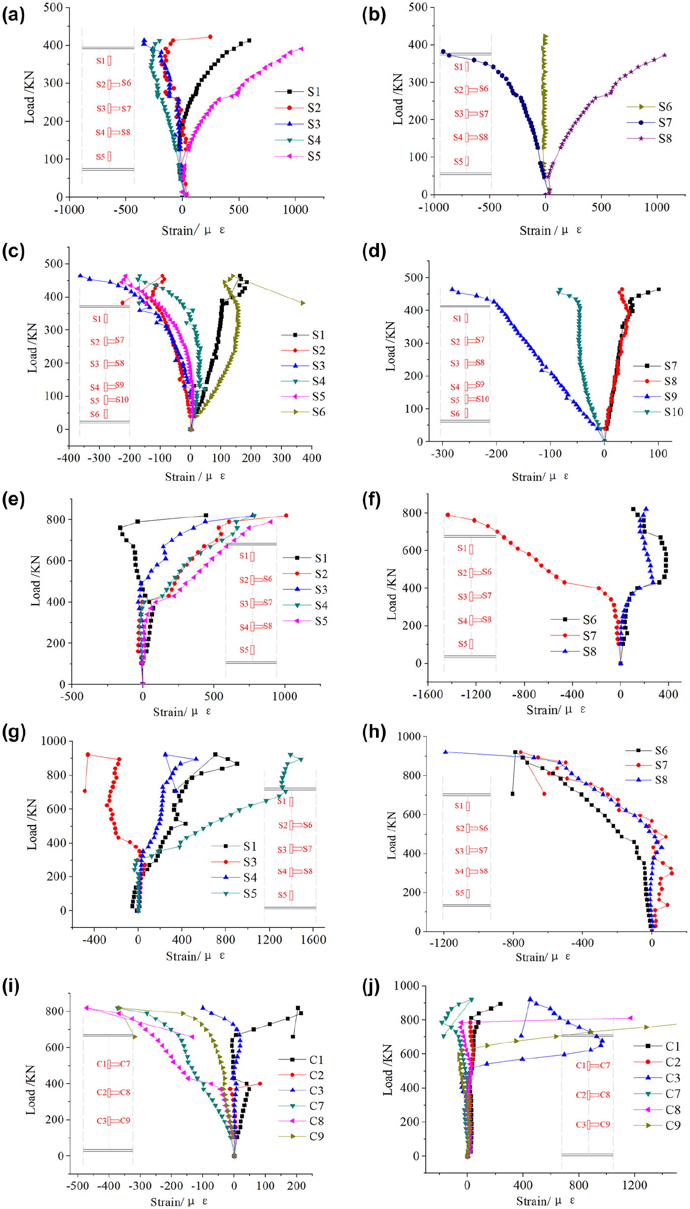
Curves of load and strain of section C-C: (a) vertical strains of specimen A-1, (b) horizontal strains of specimen A-1, (c) vertical strains of specimen A-2, (d) horizontal strains of specimen A-2, (e) vertical strains of specimen B-1, (f) horizontal strains of specimen B-1, (g) vertical strains of specimen B-2, (h) horizontal strains of specimen B-2, (i) concrete strains of specimen B-1, and (j) concrete strains of specimen B-2.
Figure 11 shows the height distribution of the vertical strains in the web at the different loading stages. In specimens without concrete encasement, the vertical steel strains of corrugated webs distribute more uniformly along the height of the web than that with flat web. For B-2, the strain at the center of the web is larger than that of the other parts. Figure 12 shows the height distribution of the horizontal strains in the web at the different loading stages. Similarly, the strains of corrugated webs distribute more uniformly along the height of the web than that of flat web, because of the accordion effect.
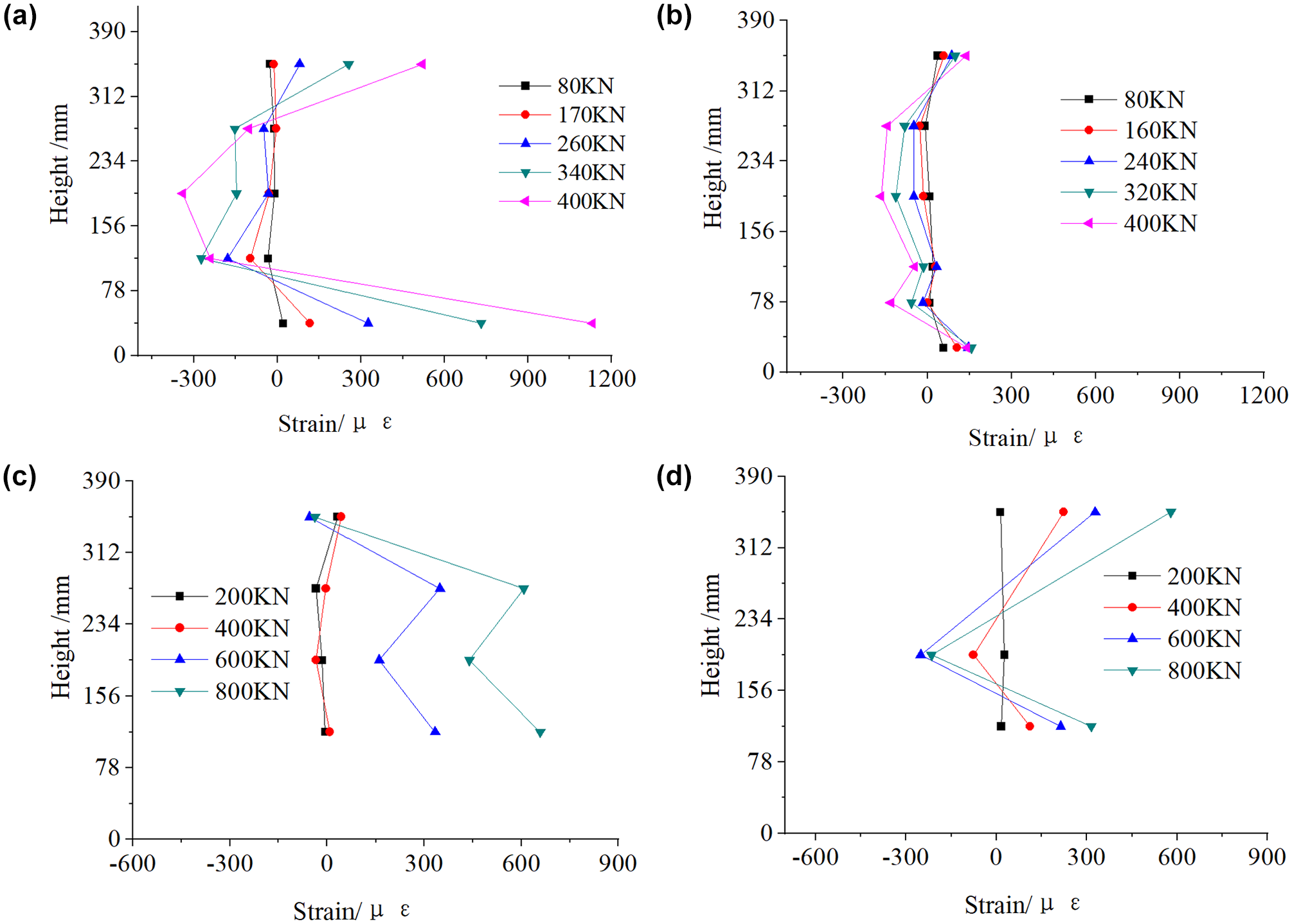
Vertical strain in the web distribution along the height of section C-C: (a) A-1, (b) A-2, (c) B-1, and (d) B-2.
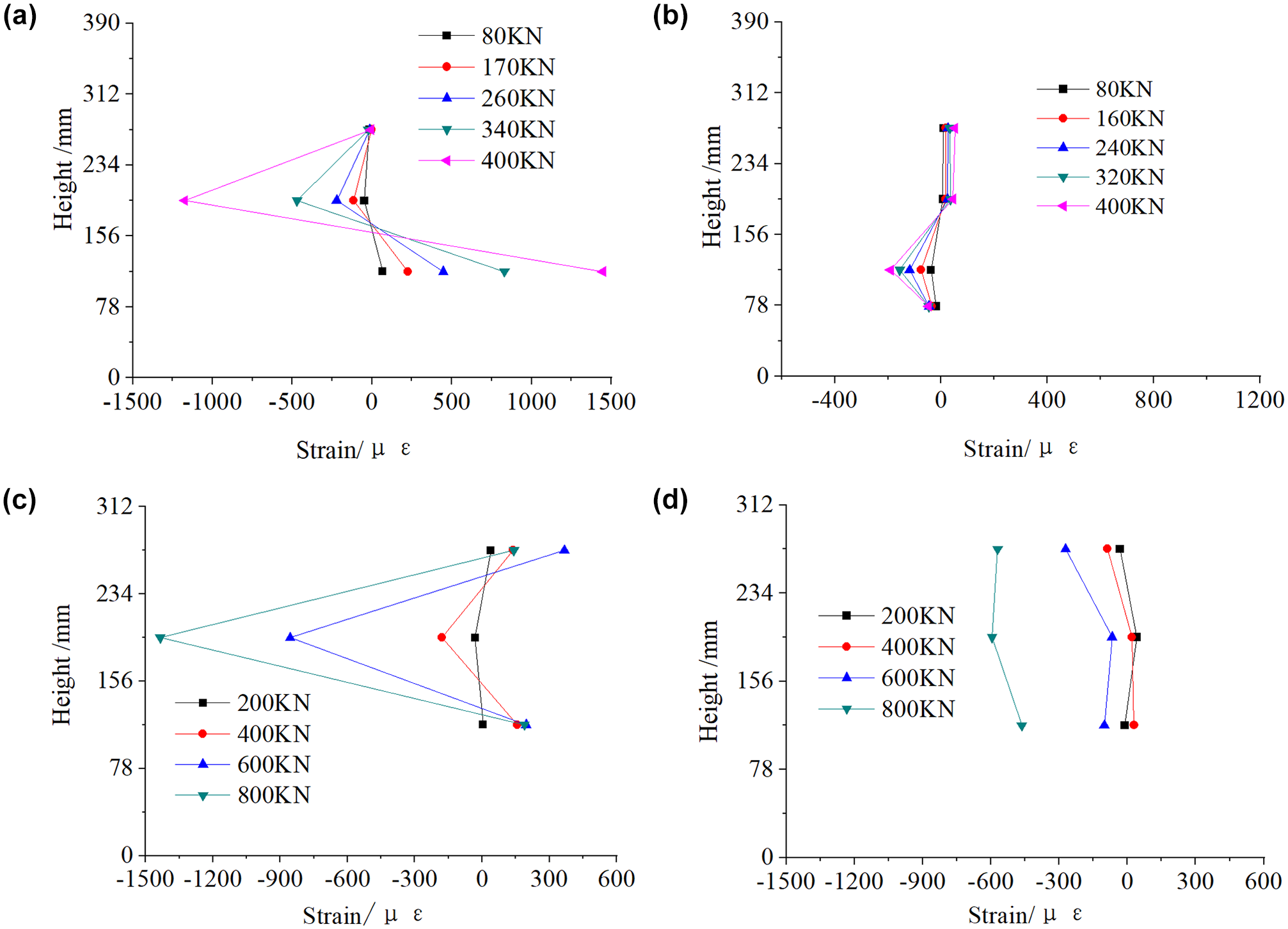
Horizontal strain distribution along the height of section C-C: (a) A-1, (b) A-2, (c) B-1, and (d) B-2.
Formulae for Shear Strength
The ratio of load shared by the steel web Vs and the concrete Vc can be described as ( 11 ):

where
η = the ratio of the developed length of one corrugation to its projected length,
E s = Young’s modulus and of the steel web,
v s = Poisson’s ratio of the steel web,
E c = Young’s modulus of the concrete,
v c = Poisson’s ratio of the concrete,
t s = web thickness, and
t ceq = concrete encasement thickness.
The experimental strain ratio of strain gauge S3 and C2 under the elastic stage is compared with the theoretical equivalent shear stiffness calculated according to Equation 1 (as shown in Figure 13). The comparison results indicate that the shear force resistance ratio for each component of the composite girders can be predicted according to their shear stiffness under the elastic stage.
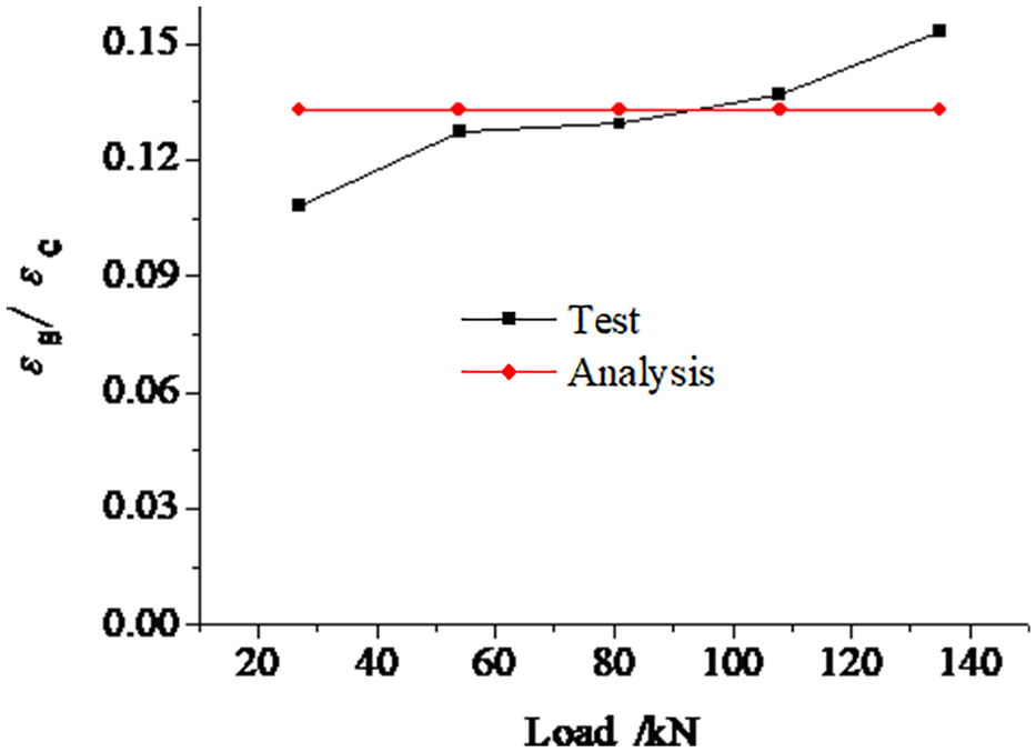
Vertical strain of elastic stage.
Nakamura and Narita presented an analytical model to calculate the shear strength of the encased composite girders, in which the steel tension strut and the concrete compression strut formed a X-truss (as shown in Figure 14) ( 17 ). The shear strength is the sum of the tension strut component and the compression strut component. For the partially encased composite girder with corrugated web, the shear stress along the height of web is assumed to be uniform, and at the ultimate state it reaches yielding strength before web bucking, so the shear strength of the corrugated web is calculated as follows:

where
V seq = the shear resistance of the corrugated web,
τ y = the shear yielding stress of the corrugated web,
t s = the thickness of the corrugated web, and
h = the height of the corrugated web.
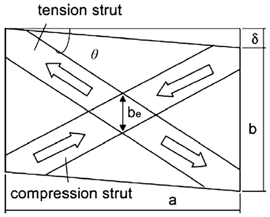
Shear resistance diagram ( 16 ).
The shear strength of concrete is calculated as follows:


where
L = the shear span of the specimen,
θ = the angle of the diagonal line in the shear panel,
f c = the compressive strength of the concrete, and
β = a ratio of the effective height of the compression strut divided by the actual web height (assuming that only this effective part contributes to the shear strength).
The shear strength V is the sum of the tension strut component and the compression strut component, as shown in Equation 5:

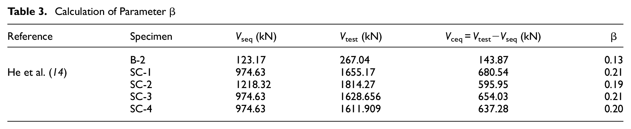
According to Nakamura and Narita’s study, β is 0.3 ( 17 ). However, in Equation 3, β is an undetermined coefficient. The analysis of coefficient β is listed in Table 3 according to the test data of specimen B-2 and other related research ( 14 ). For the design, the theoretical data must be less than the test data from the view of security. Therefore, β is assumed to be 0.13.
Calculation of Parameter β
Shear Strength of the Real Bridge
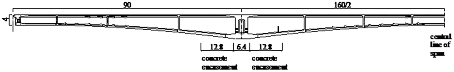
The Qishan River bridge (as shown in Figure 15) is a three-span (90 + 160 + 90 m), prestressed box girder with encased concrete. The dimensions of the concrete encasement is shown in Figure 16. The concrete has a design compressive strength of 60 N/mm2 and Young’s modulus of 36,000 N/mm2. The steel girders are made of steel Q345 with a nominal tensile yielding stress of 340 N/mm2 and Young’s modulus of 200,000 N/mm2.
The real bridge with main spans (unit of measure: metres).
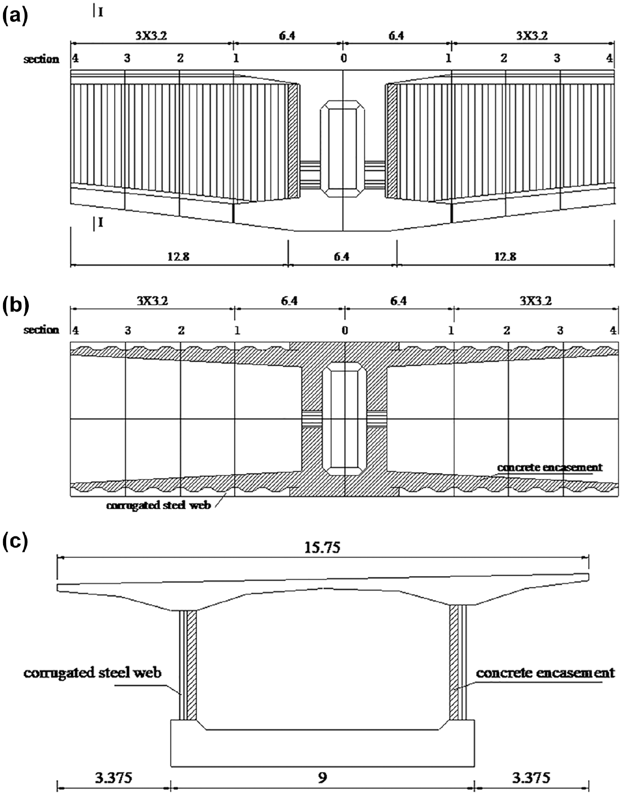
Concrete encasement (unit of measure: metres): (a) elevation view, (b) upward view, and (c) section I-I.
Finite element modeling of the real bridge (as shown in Figure 17) was carried out, taking into account the construction stage. Spatial beam elements were employed for modeling a continuous PC box girder with corrugated steel webs. The corrugated steel web was equivalent to a flat plate, taking into account the accordion effect of the web.
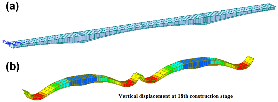
Finite-element model of the real bridge: (a) Finite-element model of the real bridge, and (b) vertical displacement at 18th construction stage.
The shear demands for the box girder are shown in Figure 18, taking into account the load combination of permanent loads and transient loads (vehicular force, temperature gradient, uniform temperature, and settlement). The approximate value of the angle of the diagonal line in the shear panel is 45 degrees. The shear strength of sections 1–4 was computed according to Equation 5 and compared with the shear demands (as shown in Figure 19). The shear strength is larger than the shear demand, according to Figure 19, so the Qishan River bridge has a safe shear design of a cross-section with corrugated steel web encased with concrete.
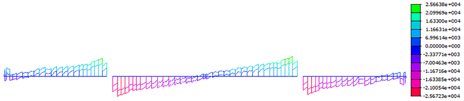
Shear force envelopes for three spans (unit of measure: kN).
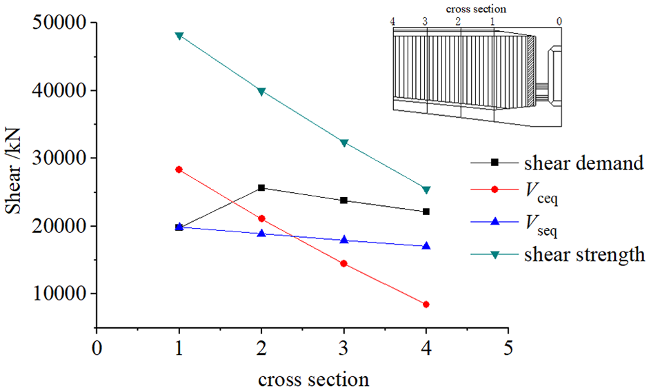
Shear demand and shear strength of sections 1–4.
Conclusions
The shear behavior of steel-composite girders with flat and corrugated web have been investigated by model experiments. The following conclusions may be drawn from the present study:
For partially encased composite I-girders, cracks initiate along the diagonal line on the surface of the concrete with load increase, then the steel web yields. Finally, the concrete crushes near the loading position when the principal compressive stress of the concrete reaches the ultimate strength. The composite girders with a corrugated web have superior shear strength compared with the steel girders with a corrugate web.
The lateral deformation of the composite girders is larger than that of the steel girders because the shear buckling is restricted by the concrete encasement. The steel strains of corrugated webs distribute more uniformly along the height of the web than for that with a flat web.
The shear force resistance ratio of each component of composite girders can be predicted according to its shear stiffness under elastic stage based on the proposed formula in this paper.
The shear strength of corrugated steel plate encased with concrete is the sum of the tension strut component and the compression strut component. The ratio of the effective height of the compression strut divided by the actual web height is assumed to be 0.13 according to experimental data. The uniformly yielded shear strength of the corrugated web is used instead of the tension strut.
The shear demand and shear strength of the real bridge are calculated based on the finite element model and the presented strength model. Research results show that the real bridge has a safe shear design of cross-section with a corrugated steel web encased with concrete.
Footnotes
Author Contributions
The authors confirm contribution to the paper as follows: study conception and design: W. Zhang, Q. Wei; data collection: X. Xu, G. Huo; analysis and interpretation of results: H. Xu, R. Lv, J. Ge, Q. Wei; draft manuscript preparation: S. Sun. All authors reviewed the results and approved the final version of the manuscript.
Declaration of Conflicting Interests
The author(s) declared no potential conflicts of interest with respect to the research, authorship, and/or publication of this article.
Funding
The author(s) received no financial support for the research, authorship, and/or publication of this article.