
Abstract
In railway tracks, fishplates are attached to each side of two rail ends and secured with four bolts, providing what is known as a bolted rail joint (BRJ). This rail joint is involved in complex interactions between multiple components under wheel loads, leading to stress and deformation of each component, potentially resulting in failures of the railway track. In this study, the different roles of selected fishplate models in the structural performance of a BRJ under static load are investigated using finite element analysis with ABAQUS CAE. Three fishplate models are examined: a thin cross-section, a thick cross-section, and a modified design. The first two models are currently used in rail transportation, while the novel modified version is designed to enhance the structural performance of BRJs. Preliminary results indicate that using the modified fishplate significantly reduces stress on the upper rail fillet and fishplate. Additionally, vertical displacement in both the rail and fishplate is diminished. These improvements are expected to increase the service life and reliability of BRJs, thereby contributing to safer and more cost-effective railway operations.
Introduction
In railway tracks, the bolted rail joint (BRJ) plays a key role in aligning rail ends in both the longitudinal and vertical directions. It uses two fishplates, one on each side of the rail ends. They are fastened with four or six bolts to ensure the smooth operation of trains. However, BRJs are involved in complex contact interactions between multiple component surfaces under load conditions. As a result, stress propagates from the contact surfaces to the inner geometry, which can lead to serious failures such as upper rail fillet separation, rail-end bolt hole cracks, and fishplate damage ( 1 – 3 ). In some cases, train derailments are caused by cracked and broken fishplates ( 4 ). These researchers conducted two finite element analyses (FEA), applying loads at the center and away from the BRJ to investigate the bending stresses of the fishplate for fatigue life calculation. The results revealed that the bending stress was concentrated at the fishplate head beneath the rail end contact under both loading conditions. This stress concentration was likely related to the cracks observed in the middle of the fishplate during crack detection analysis performed using a video inspection system under a moving vehicle ( 2 ). Akhtar et al. stated that cracks often initiate from points of maximum stress, such as bolt holes or the edges of fishplates, especially when loading is combined with factors such as poor track alignment, degraded ballast, and corrosion over time ( 5 ).
Studies have examined the distribution of von Mises, bending, principal, shear, and fatigue stresses, as well as deformation in BRJs under different support conditions (i.e., supported, near the support, or suspended) with loads applied at the mid-span ( 6 – 9 ). The stress distribution was higher on a BRJ when it was suspended between sleepers. Then, the stress and vertical displacement increased at the upper rail fillet and the rail end, respectively. Wondimu et al. studied the effect of operating speeds and bolt tightness ( 10 ). They observed that the fishplate suffered maximum deformation when the train wheel passed over the rail end. This was especially true when a bolt was loose, posing a major risk for the service life of the rail joint structure. Additionally, it was found that the stress in the upper rail fillet and displacement of the rail end could increase if there were loosened or missing bolts near the gap of the BRJ ( 11 ). Samantaray et al. also performed two bolt looseness exercises in a BRJ to investigate the rail joint structure integrity by finding the stress and deformation on the BRJ components (i.e., rail, fishplate, and bolts) from FEA results ( 12 ). Peak von Mises stress occurred at the rail bolt holes and the fishplate contact surface, while the maximum deformation was observed in the middle of the fishplate. Mandal analyzed vertical and longitudinal stress and deformation at the middle of a fishplate and the bolt hole center to modify the geometric design ( 13 ). The results suggested that stress concentration occurred at the bolt hole center, and maximum vertical deformation was in the middle of the fishplate.
Mandal and Peach investigated the performance of three fishplate sizes in the rail joint, studying the stress in both the railhead and fishplate as well as the vertical displacement ( 14 ). Their results showed that using a thicker fishplate reduced stress and displacement in the components, owing to its larger section modulus. Igwemezie and Nyguyen evaluated the performance of existing fishplate designs and developed a new design, consisting of web-hugging bars and a saddle for use in a suspended condition ( 15 ). This new design reduced stress in the fishplate head and base, as well as displacement at the bottom of the rail joint. Sheikh et al. calculated the fatigue life of three fishplates using theoretical analysis, suggesting that fishplates with larger cross-sectional areas and smaller values of the maximum distance from the neutral axis significantly enhanced the service life of the rail joint ( 16 ). Carolan et al. studied the structural performance of BRJs using long-toe angle and short-toe fishplates, incorporating an easement set at the recessed portion on top of the fishplate to reduce contact force and pressure between the rail end and the fishplate ( 17 ). It was found that a fishplate with an easement significantly reduced contact force on the fishplate and contact pressure in the rail joint, but had only a minor effect on deflection. Then, Qian et al. performed a parametric analysis of the easement design with varying lengths and depths at the center of the fishplate head, focusing on the von Mises stress of the upper rail fillet ( 18 ). Longer easements reduced stress at the rail end, and greater easements resulted in lower contact stress. Zhu et al. studied the role of standard, thick, and long fishplates in BRJs under static loads applied at the rail end and rail-end bolt hole ( 19 ). They found that using the standard fishplate produced significantly higher stress in the upper rail fillet and end bolt hole with larger vertical displacement than a thick fishplate. This was probably because of its lower section modulus.
As discussed in the literature, stresses in the upper rail fillet, rail-end bolt hole, and the fishplate, as well as deflection at the rail joint, were highest under specific conditions. These were when the rail joint was suspended, the bolt preloading was loose, or when fishplates with smaller section properties were used under loads applied on the end. Based on these factors, this article evaluates the role of the fishplate models in BRJs by applying normal bolt preloading as described by Le and Wongsa-Ngam to investigate the structural performance of rail joints ( 20 ). In this study, the term “structural performance” refers to the comparative mechanical response of the BRJ, as measured by von Mises stress and vertical displacement. These indicators are used as structural response criteria to identify high-risk locations and to compare the effectiveness of different fishplate configurations. The influence of fishplates on the rail at the joint regions, with particular focus on failure areas such as the upper rail fillet and end bolt hole, is investigated. There is limited research in this area. First, two existing fishplate models are used. This is done in the BRJ to determine critical stress on the upper rail fillet, lower fillet, rail-end bolt hole, second bolt hole, and the fishplate head and base, as well as vertical displacement. Subsequently, a modified fishplate is proposed and implemented in a BRJ to reduce stress in these regions, minimize displacement, and extend service life. The BRJ is modeled as a 3D solid component using ABAQUS CAE for FEA numerical simulation. FEA is an effective tool for studying and solving the structural performance of BRJs, even in multibody systems.
Methodology
Finite Element Modeling
The specifications for the BRJ structure were based on those currently used by the State Railway of Thailand. The parts of the BRJ, including the rail, fishplate, bolt, and sleeper, were modeled in ABAQUS CAE. The rail profile was BS 100, with a 1961.00 cm4 moment of inertia. Two different fishplate models were used for the BRJ, categorized as “thin” and “thick” fishplates (existing fishplates). The length of the fishplates was 457.2 mm. Their section properties, that is, the moment of inertia, the perpendicular distance from the neutral axis to a point farthest from the neutral axis, section modulus, and mass, are provided in Table 1. The bolts, nuts, and washers were simplified as a single unit to reduce the rail joint complexity ( 11 ). The sleeper length was modeled using only half of the full profile for a single railroad simulation. Then, the solid parts were assembled by connecting the rail ends with fishplates, secured with bolts at the mid-span of two adjacent sleepers, forming the BRJ structure in a suspended configuration. The two rail ends had a gap of 6.34 mm, and the rail tracks were supported by sleepers with a uniform distance of 600 mm ( 20 ). The BRJ structure is depicted in Figure 1. It shows a 3D view of the FEA model, including the boundary conditions, and illustrates the XY (cross-sectional) view of the BRJ for both thin and thick fishplates.
Section Properties of the Existing Fishplates
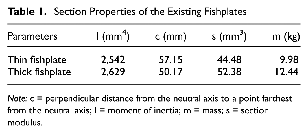
Note: c = perpendicular distance from the neutral axis to a point farthest from the neutral axis; I = moment of inertia; m = mass; s = section modulus.
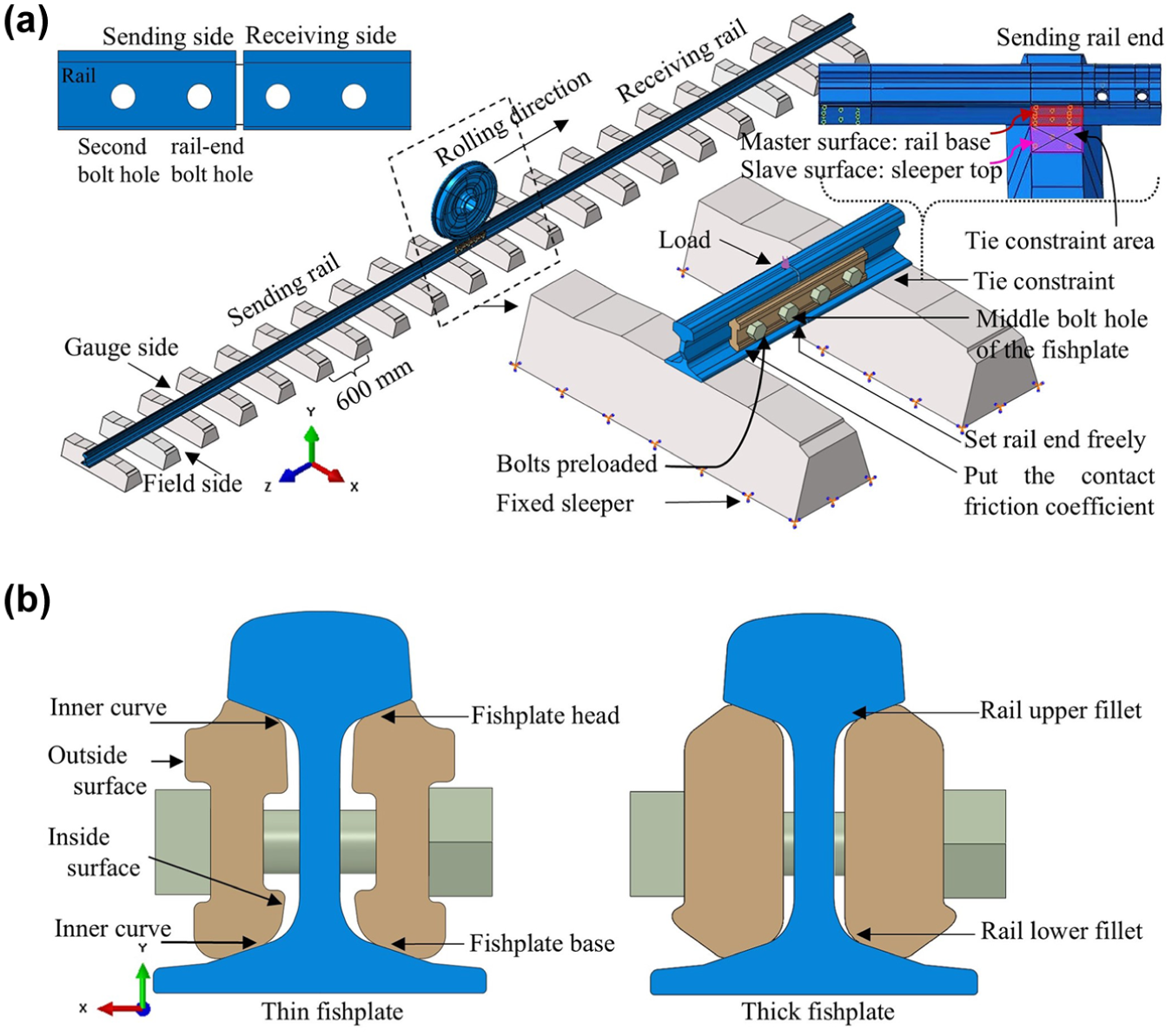
The bolted rail joint (BRJ) structure: (a) 3D view of the finite element analysis model and its boundary conditions and (b) cross-sectional view of the BRJ using the thin and thick fishplates.
Finite Element Analysis
The 3D Cartesian coordinates in the FEA model are defined as follows. X, Y, and Z are the lateral, vertical, and longitudinal directions. The material properties for all parts of the BRJ conform to linear elastic conditions, as shown in Table 2 ( 10 , 21 ). The Young’s modulus, yield strength, Poisson’s ratio, density, and material types are shown in this table.
Mechanical Properties for All Parts of the Bolted Rail Joint
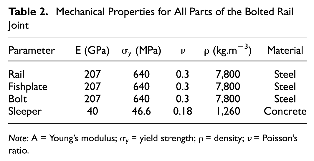
Note: A = Young’s modulus;
Two loading steps were considered. Step 1 was the bolt preload. Here, the fishplates were clamped onto both sides of the rail ends by bolts to prevent the separation of individual components at the BRJ under wheel loads. This preload was developed with a tensile force in the bolt, which caused a set of normal forces in the fishplate contact areas, ensuring support and/or contact with the rail ( 22 ). The bolt preload (P b ) equation is:

where
T = the bolt torque (500 N·m),
D = the bolt diameter (25.4 mm), and
The calculated bolt preload was 98.4 kN per bolt, which was uniformly applied to the internal axis of the bolts, as shown in Figure 1a ( 20 ). This preload was in the recommended range of 89.0–133.4 kN per bolt, as specified in the American Railway Engineering and Maintenance-of-Way Association (AREMA) manual ( 23 ).
Step 2 involved the wheel load, 130 kN. It was transformed into an ellipsoidal Hertzian pressure distribution applied to the BRJ ( 20 ). A wheel load was applied on the rail end (at the sending side) to evaluate the maximum stress and displacement, representing a critical condition for the BRJ’s structural performance ( 18 , 19 ), as shown in Figure 1a. Among numerous parts of the BRJ, only the rail and fishplate on the sending side are presented in the FEA results section.
In the BRJ, the contact surfaces between the rail and fishplate, between the fishplate and bolt, and between the bolt and bolt hole yielded a 0.3 friction coefficient ( 1 ). To simulate the clamping force of rail clips, they are compressed on both sides of the rail foot to prevent vertical, lateral, and longitudinal movement. Two key boundary conditions can be defined: 1) a normal load applied to the clip contact regions to represent the preload for failure analysis of the rail foot and 2) a self-contact applied between the rail and clips for analyses focusing on areas away from the direct clip zone. For the interface between the rail base and the sleeper, a simplified surface-to-surface tie constraint can be used in the regions of contact. This constraint effectively bonds the surfaces, meaning the rail base experiences direct tension when a load is applied to the rail end. (Note: The solid geometries of the rail and sleeper themselves were not merged; only their contacting surfaces were tied.) This modeling approach was chosen because the tie constraint provides an equivalent structural effect to clamped connections for this analysis, while significantly reducing model complexity and improving computational efficiency. Therefore, the rail was still allowed to move vertically like an in-service rail under load in the boundary conditions. The sleepers are fixed at the base to restrict their movement, as seen in Figure 1a. All the BRJs in Figure 1b followed the same boundary conditions in the numerical simulation. It should be noted that the present FEA model does not explicitly include the detailed stiffness contributions of the full track substructure. These factors may influence the rail support condition and overall joint response in service. In this study, a simplified support representation was adopted to isolate the effect of fishplate geometry on the structural response of the BRJ. The inclusion of track resiliency and more realistic support conditions is recommended for future work.
The meshing model of the BRJ structure utilized eight-node trilinear brick (C3D8) elements, which are well-suited for solving solid component problems ( 13 , 24 – 26 ). To achieve accurate results, fine meshes were employed in the BRJ region, while coarser meshes were used for regions further from the rail joint, as shown in Figure 2. This was done to optimize computational efficiency. A mesh convergence analysis was conducted to validate the FEA results. Six mesh elements were tested in the case of the thin fishplate installed in a BRJ, consisting of 692,079, 701,091, 726,561, 799,092, 101,6064, and 177,6470 elements. The highest stress values in the rail were evaluated and plotted via mesh convergence analysis, as shown in Figure 3. The last three meshes demonstrated convergence, with stress values increasing from 628 MPa to 639 MPa, a difference of only 1.8%. This is within the acceptable range reported by Zhu et al. ( 19 ). As a result, a 799,092-element mesh was selected for the FEA simulations to achieve computational efficiency while retaining accuracy.
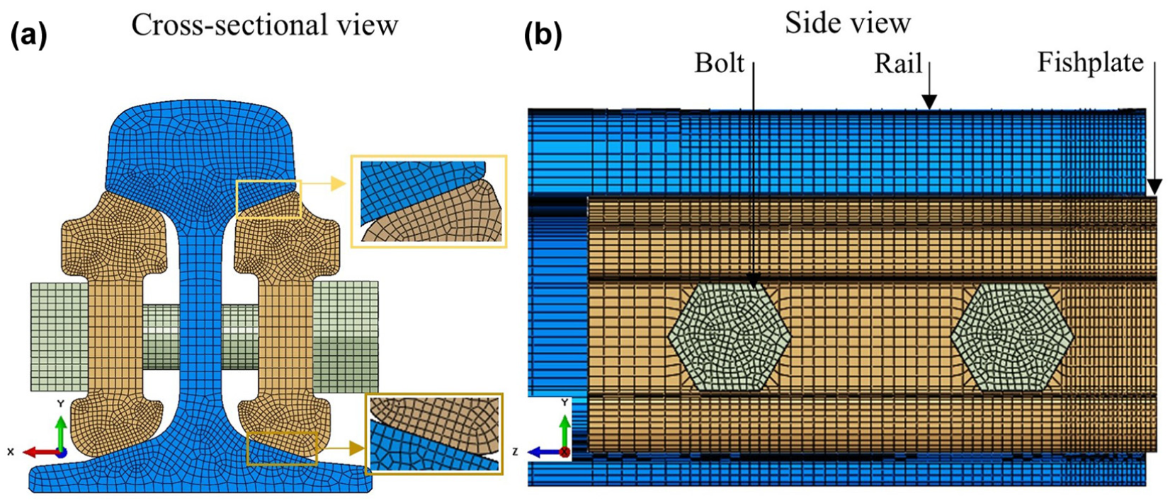
Meshing model of the bolted rail joint: cross-sectional view (left) and side view (right).
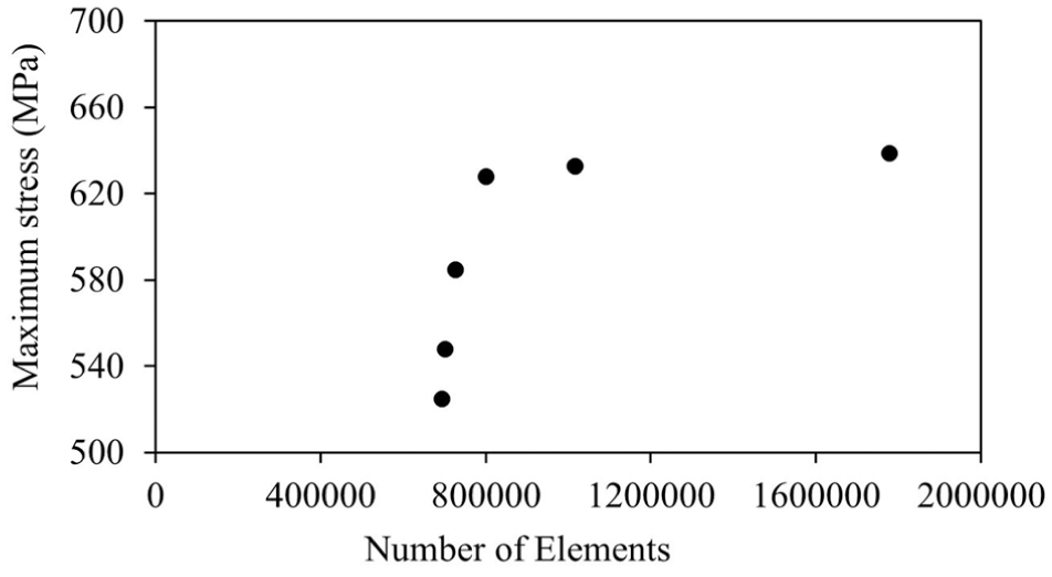
Stress analysis for mesh convergence.
FEA Results Based on the Existing Fishplates
Stress Distribution on the BRJ: Rail and Existing Fishplates
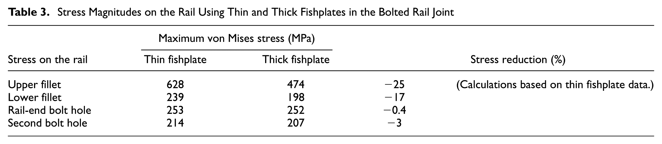
The BRJ structure exhibited a higher von Mises stress distribution on the contact regions (between the rail and fishplate, between the fishplate and bolt, and between the bolt and bolt holes) under the load applied on the rail end, as shown in the cross-sectional view of Figure 4. These results are consistent with recently published models ( 8 , 15 ). Elevated stress at the contact surfaces of the rail fillets and fishplate (head and base) occurred at the normal contact point of the fishplate, which was fastened by the bolt preload. In the suspended BRJ configuration, the rail was assumed to behave as a cantilever beam. When a wheel load was applied, the rail end bent and came into firm contact with the fishplate. As a result, the highest stress occurred at the edge of the upper rail fillet, as illustrated in the rail cross-sectional views of Figure 4, a and b . In contrast, the lower fillet had significantly less stress because it was closer to the original load transmission area ( 20 , 27 ). Additionally, the stress in the rail web was more pronounced around the rail-end bolt hole, while the second bolt hole showed less stress, as depicted in the side views of the rail in Figure 4, a and b ( 20 , 28 , 29 ). A greater stress distribution at the rail-end bolt hole occurred within the 0° ± 45° range relative to the longitudinal axis, which correlated with regions where cracks had occurred ( 1 , 30 ). The maximum stress magnitude values on the upper rail fillet, lower fillet, rail-end bolt hole, and second bolt hole for existing fishplates are presented in Table 3. Using a thick fishplate in a BRJ significantly reduced stress in the upper fillet because its sectional properties were more effective at mitigating stress than a thin fishplate ( 19 ). The stress values at the lower fillet, rail-end, and second bolt holes were also reduced when using the thick fishplate.
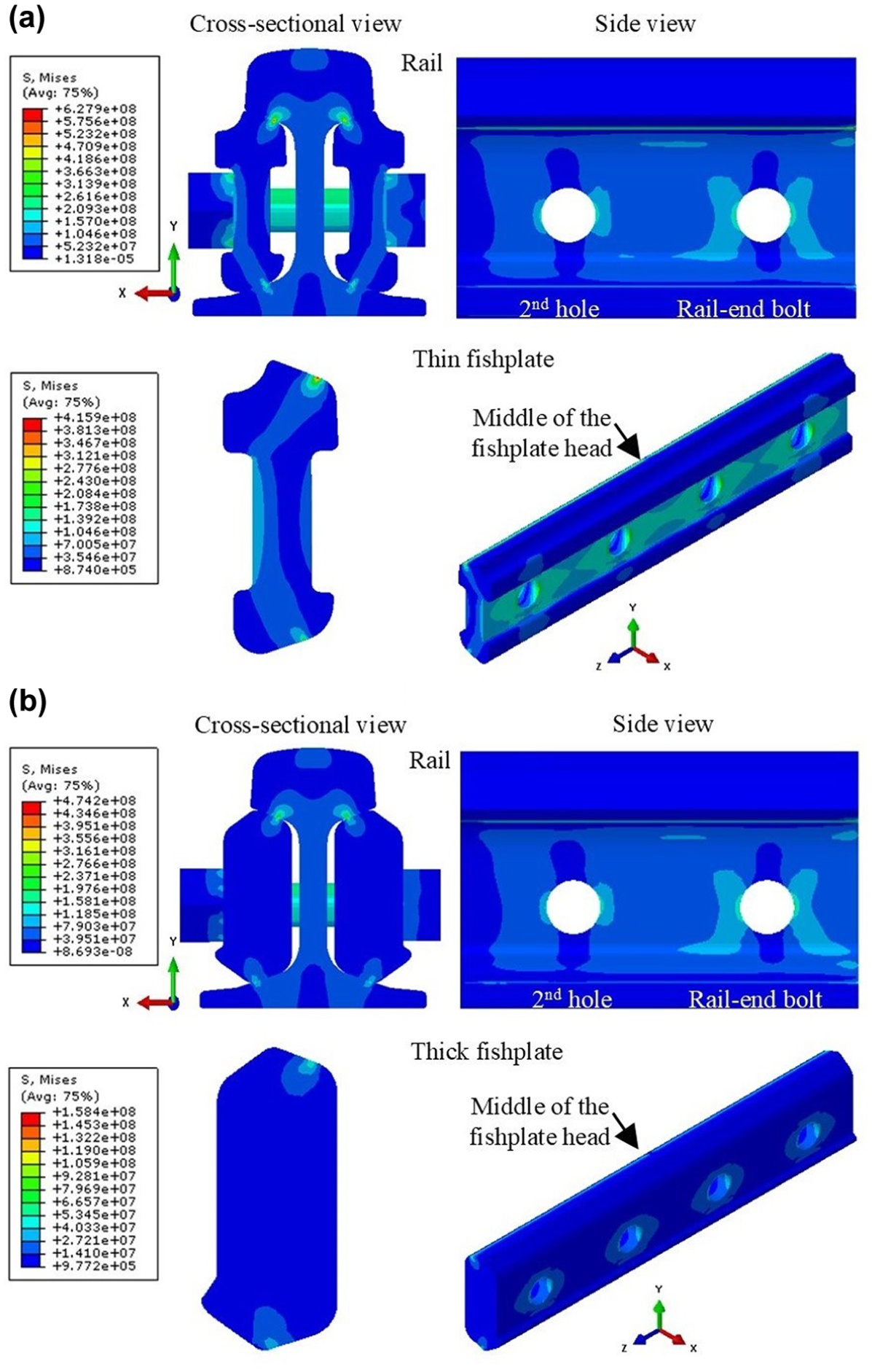
Stress distribution: (a) stress on the bolted rail joint (BRJ) (rail and thin fishplate) and (b) stress on the BRJ (rail and thick fishplate).
Stress Magnitudes on the Rail Using Thin and Thick Fishplates in the Bolted Rail Joint
In a more detailed analysis, higher stress was observed over the thin fishplate web, especially around the bolt holes, as shown in the 3D view of the thin fishplate in Figure 4a. This stress in the web and bolt holes was because of the web’s smaller cross-section, which weakened its ability to withstand bolt preloading and wheel load effects, and contact stress between the bolt and bolt hole, respectively. However, the maximum stress, 416 MPa, occurred in the middle of the fishplate head, which is underneath the rail end under loading ( 14 , 31 ). This stress was concentrated near the inner curve of the fishplate head, as shown in the cross-sectional view in Figure 4a. Since the thin fishplate was positioned slightly farther from the rail, the normal contact point where the fishplate supported the rail fastening via bolts was located near the inner curve of the fishplate head. This configuration caused the surfaces to taper inward, leading to higher stress concentrations. Additionally, the measured stress near the inner curve of the fishplate base was 185 MPa, significantly lower than that of the fishplate head. Concurrently, the stress on the outside surface of the fishplate head (i.e., below the contact surface) was lower, as indicated by the contour of the color legend in Figure 4a. Both the inside and outside surfaces of the fishplate base (i.e., above the contact surface) exhibited minimum stress.
However, the higher stress on the thick fishplate web was localized around the bolt holes, as shown in the 3D view in Figure 4b. Maximal stress occurred at the center of the thick fishplate head, 158 MPa. Since the thick fishplate was installed closer to the rail web, the normal contact point was positioned midway along the inclined surface of the fishplate head. The stress was spread more evenly across the middle of the contact surface, leading to lower stress values than the thin fishplate. The measured stress at the fishplate base, 88 MPa, was concentrated around the outer curve of the fishplate base. The thick fishplate showed enhanced resistance to the wheel load, with reduced stress on its head, base, and web because the thick fishplate had a higher section modulus.
Vertical Displacement of the BRJ: Rail and Existing Fishplates
Studies of rail vertical displacement for thin and thick fishplates showed that the maximum displacement occurred at the rail foot near the end, as illustrated by the side view of the rail in Figure 5, a and b . This maximum displacement was because of the rail foot resisting the entire length of the fishplate, which stood between the sleeper spacing at the rail joint during loading. Furthermore, the rail web stretched vertically because the rail end of the BRJ was displaced in a suspended configuration under load, as well as because of the compressive force of the bolted fishplates. The maximum rail displacement was 0.0320 mm using the thin fishplate in the BRJ, as illustrated in Figure 5a. It was 0.0319 mm using the thick fishplate, as shown in Figure 5b. The thick fishplate reduced rail displacement because it had a larger cross-sectional area and was installed closer to the rail web. This improved its capability to resist wheel loads.
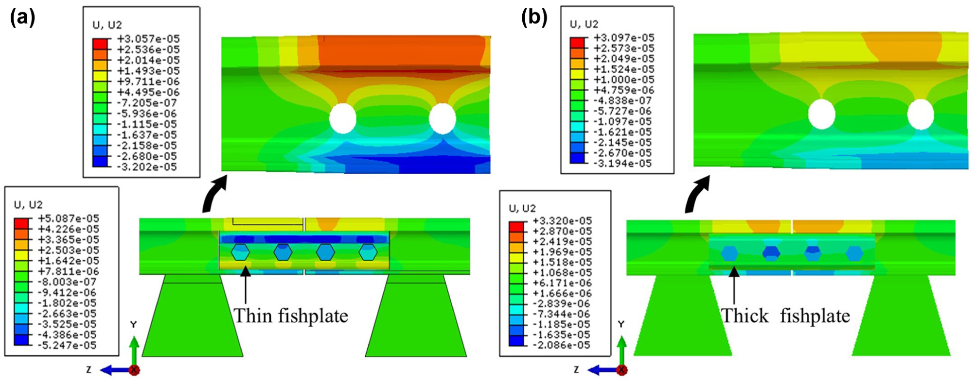
Vertical displacement of the bolted rail joint: (a) rail and thin fishplate, and (b) rail and thick fishplate.
As shown in the side views of the BRJ in Figure 5, a and b , the vertical displacement of both thin and thick fishplates was highest in the middle head, near the load application area, 0.0525 and 0.0209 mm, respectively. This was because of the thick fishplate’s higher moment of inertia and mass, as well as its installation closer to the rail web. As a result, the thick fishplate exhibited significantly smaller displacement ( 19 ).
The Modified Fishplate
The thick fishplate had a larger cross-section and a smaller perpendicular distance from the neutral axis to a point farthest away. This resulted in a greater moment of inertia and section modulus, respectively. Additionally, the thick fishplate was positioned closer to the rail web, enhancing the rigidity of the BRJ structure. Consequently, stresses in the upper rail fillet, lower fillet, rail-end bolt hole, and second bolt hole, as well as the vertical displacement of the rail foot, were reduced. Additionally, the stress and vertical displacement in the thick fishplate head were significantly reduced. However, the thick fishplate increases the static weight of the BRJ in railroad tracks and is thus less economical for users.
In contrast, the thin fishplate had a narrow cross-section at the web and the largest value of the perpendicular distance from the neutral axis to a point farthest away. This results in a smaller moment of inertia and section modulus. Moreover, the thin fishplate was positioned slightly farther from the rail web, which may have reduced the rigidity of the rail joint and increased bending. Consequently, the normal contact point is near the inner curve of the thin fishplate, making it prone to surface taper inward. These factors contributed to peak stress in the rail and fishplate, as well as increased stress in their bolt holes. The displacement of the rail foot also increased. Additionally, the stress and displacement of the thin fishplate head were substantially higher. When using the thin fishplate, the maximum stress in the upper rail fillet and thin fishplate head approached the yield limit and may reach its plastic limit under repetitive load cycles.
It has been established that the section properties of the fishplate are the key to impacting stress and displacement on both the rail and fishplate. Furthermore, the contact profile between the rail and fishplate is also critical, particularly at the rail end. The maximum stress position shifted on the existing fishplates’ head and base, as seen in the cross-sectional view of Figure 4. When the maximum stress occurred at the center of the fishplate’s sloped surface, it resulted in a more even stress distribution and reduced stress magnitude (shown in the cross-sectional view of Figure 4b). This behavior depended on the normal contact point of the fishplate fastening via bolts. As discussed in earlier work, a fishplate positioned closer to the rail web reduced stress on the fishplate head ( 15 ). Additionally, stresses in the fishplate head and rail end were linearly reduced by introducing easement lengths and depths along the top center of the fishplate ( 4 , 18 ). However, this did not reduce stress along the entire rail, highlighting the need for a proper easement geometry to enhance service life. When comparing thin and thick fishplates in the BRJ, the maximum stress at the middle of the fishplate head occurred under the rail end using the same loading conditions. The stress magnitude will be reduced by approaching the fishplate length near the sleeper ( 6 – 9 ).
A modified fishplate (modifications labeled 1–5 in Figure 6), was developed using the thin fishplate as a reference that incorporated the following geometric improvements:
Enlargement of the fishplate head (modification 1) at the inner curve to prevent tapering inward on the contact surface of the fishplate and rail under wheel load. The stress on the fishplate will be more evenly distributed over the contact surface, resulting in lower stress concentrations.
Widening of the fishplate web (modification 2) on the inner side to provide a greater cross-sectional area. It also aligned the fishplate more closely to the rail web, improving rail joint stability, reducing bending stress and distortion caused by the vertical wheel load and lateral bolt preload, while enhancing service life.
Cutting out some areas (modifications 3–5) to reduce the fishplate mass where stress was lower in the thin fishplate.
Extension of the fishplate length to 482.2 mm minimized rail deflection and web stretching.
These modified fishplate ends stand across from their adjacent sleepers, as depicted in Figure 6. The moment of inertia, section modulus, and mass of the modified fishplate were 2561 mm4, 44.8 mm3, and 9.67 kg, respectively.
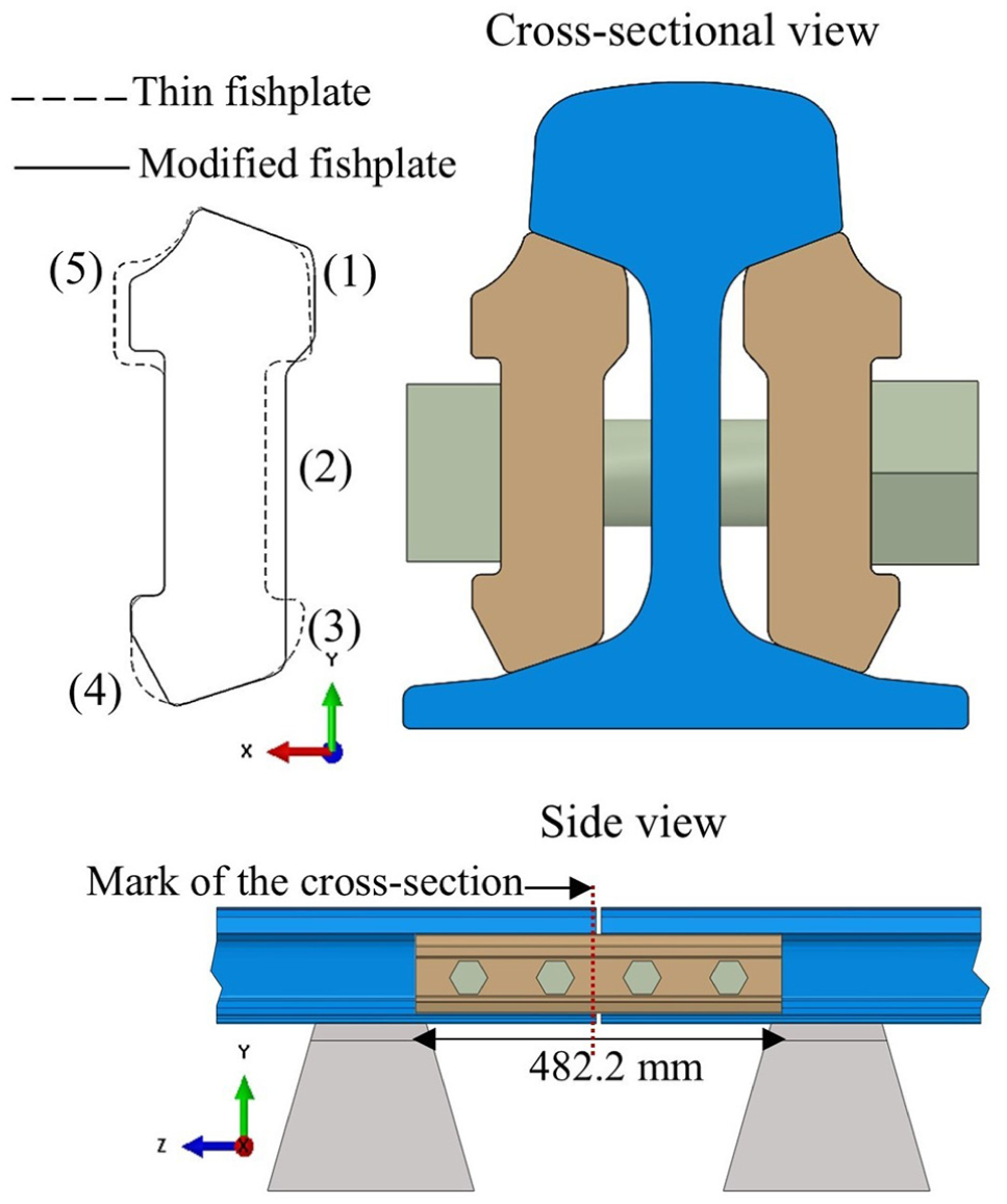
Modified fishplate used in a bolted rail joint: cross-sectional view (top) and side view (bottom).
FEA Results Based on the Modified Fishplate
Stress Distribution on the BRJ: Rail and Modified Fishplate
Using the modified fishplate, the von Mises stress at the upper and lower rail fillets was evenly expanded on the normal contact surfaces with maximal values of 448 MPa and 307 MPa, respectively. This is illustrated in the cross-sectional view of the rail in Figure 7. The stress distribution in the rail web was 251 MPa around the rail-end bolt hole and lower around the second bolt hole, at 206 MPa. This is illustrated in the side view of the rail in Figure 7.
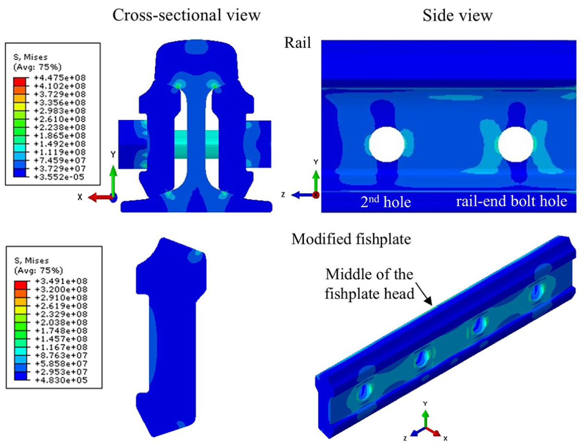
Stress distributions on the bolted rail joint (rail and modified fishplate): cross-sectional view (left) and side view (right).
Comparison with the FEA results using the existing fishplates in the BRJ, the stresses in the upper rail fillet, lower fillet, rail-end bolt hole, and second bolt hole are described in Figure 8a. In all studies, the highest stress occurred at the upper fillet, while the stress at the rail-end bolt hole was greater than at the second bolt hole. These regions of higher stress are potential points for crack initiation. Using the modified fishplate, the stresses at the upper rail fillet, rail-end bolt hole, and second bolt hole were reduced by 28%, 0.8%, and 4%, respectively, compared with the thin fishplate data. This reduction may enhance service life and can be attributed to its increased section modulus and extended length. Although the modified fishplate’s section properties did not match those of the thick fishplate, the stress at the upper fillet was reduced by 5% compared with that of a thick fishplate. This improvement may have been because of the extended length across the sleepers, which increased the rail joint rigidity and reduced the bending of the fishplate. The stress at the rail-end and second bolt holes was also slightly reduced. While the stress in the rail lower fillet increased with the modified fishplate, it remained below the yield point of the material.
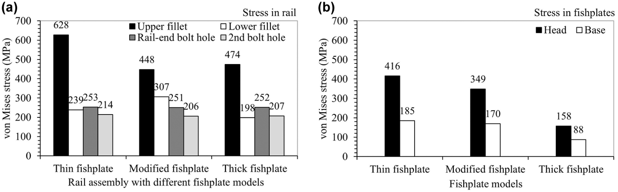
Stresses from all studies: (a) the rail and (b) the fishplate models.
Higher stress in the modified fishplate web accumulated around the bolt holes on the outer side, as evaluated by the contour plot and illustrated in the 3D view of the fishplate in Figure 7. The stress distribution diminished at the modified fishplate’s head and base, as shown in the cross-sectional view of the fishplate in Figure 7. This was because of the enlarged inner curve, cross-sectional area, and extended length, which enhanced the rail joint performance. The maximum stress values in the middle of the fishplate head and base were 349 and 170 MPa, respectively. These stresses are shifted to the center of the inclined fishplate surface compared with both the thin fishplate (head and base) and the thick fishplate (base). In each case, the maximum stress occurs at the normal contact point where the fishplate is fastened to the rail via bolts. In this model, the opportunity for tapering inward is limited, which reduces stress because the maximum stress moves away from the edge of the fishplate curve.
Stresses in the middle of the modified fishplate head and base are compared with existing fishplates in Figure 8b. In all fishplates, stress peaked at the head because of the rail end contact and bending, consistent with the crack initiation region identified by Gibert-Serra et al. ( 2 ). Stress in the modified fishplate head and base was reduced by 16% and 8%, respectively, compared with a thin fishplate. However, the stress in the modified fishplate did not decrease to the lower values observed in the thick fishplate. Its extended length had a minor effect on stress reduction compared with the thick fishplate, as the latter had a larger section modulus.
Vertical Displacement of the BRJ: Rail and Modified Fishplate
Using the modified fishplate in the BRJ, the vertical displacement at the rail foot near the gap was 0.0294 mm, as shown in the side view of the rail in Figure 9. The rail web around the rail joint region remained slightly stretched because of rail end displacement under wheel load. This resulted from the increased moment of inertia and extended length across the sleeper, which reduced the displacement of the rail in comparison with the existing fishplates, as plotted in Figure 10a. The rail vertical displacement was reduced by 8% using the modified fishplate compared with the thin fishplate. Although the modified fishplate had a lower moment of inertia than the thick fishplate, its extended length still facilitated an 8% reduction in rail displacement.
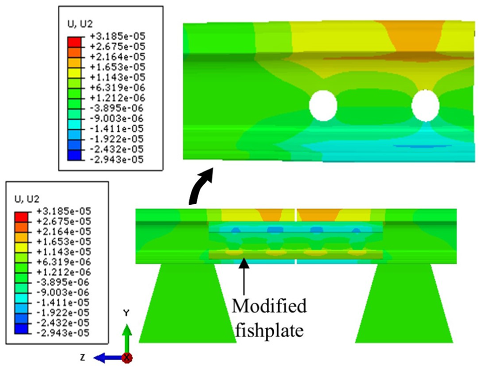
Vertical displacement of the bolted rail joint (rail and the modified fishplate).
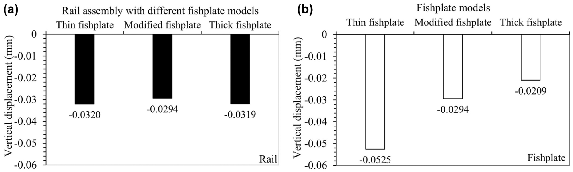
Vertical displacements from all studies: (a) the rail and (b) the fishplates.
The vertical displacement of the modified fishplate reached a maximum value of 0.0294 mm in the head, as shown in the side view of the BRJ in Figure 9. Figure 10b compares the vertical displacement results for the thin, thick, and modified fishplates. Among the fishplate models, the thin fishplate had the highest displacement. Higher displacement accelerates track degradation which, in turn, affects structural performance, leading to issues such as small steps (altering the original gap), rail height mismatch, rail end batter, bolt looseness, and ballast deterioration ( 4 ). The modified fishplate demonstrated a 44% reduction in displacement compared with the thin fishplate, owing to its higher moment of inertia. However, its displacement was as low as that of the thick fishplate, which had the highest moment of inertia in this study.
The stress and displacement results for the rail and fishplates were used as comparative structural response measures in the performance analysis of the BRJs. These measures helped identify mechanically critical regions within the BRJ and compare the effectiveness of different fishplate configurations. In particular, elevated stress near the upper rail fillet, rail-end bolt hole, and fishplate head may indicate locations susceptible to crack initiation or accelerated deterioration, while larger vertical displacement may contribute to joint looseness and track degradation. However, the direct prediction of rail defect development and rail service life would require additional fatigue, damage-evolution, and long-term loading analyses, which are beyond the scope of the present study.
The initial performance analyses were conducted solely on the suspended BRJ to identify the regions of maximum stress and displacement on the rail and fishplate for design purposes. Although comparison with the performance of a supported BRJ may show lower stress and displacement, indicating better structural performance as discussed in published works, the suspended configuration is critical (6–9). This is because it reveals the essential risk regions in the existing models, which is necessary for a modified design. The modified fishplate demonstrated better stress distribution and lower displacement in the rail than the other two fishplates. Furthermore, it showed improved performance over the thin fishplate, and its mass was 3% lower. This reduction decreases the amount of metal required for production, resulting in a slight cost savings. Although the modified fishplate did not match the structural strength of the thick fishplate, which had superior section properties, its mass was 29% lower, making it a more economical choice for practical applications.
Conclusions
An FEA of the BRJ’s structural performance was successfully conducted in ABAQUS CAE considering the roles of the fishplate models under static wheel loads. This study investigated the stress at the rail (upper fillet, lower fillet, rail-end bolt hole, and second bolt hole), and the fishplate (head and base), as well as the vertical displacement of the rail and fishplates. The stress distribution regions were consistent with published research findings. The main findings about the use of different fishplates in the BRJ are as follows:
Using the modified fishplate in the BRJ, the stress in the upper rail fillet was reduced by 28%, while the rail displacement decreased by 8% compared with the thin fishplate baseline.
The stress reduction in the upper rail fillet was 5% using the modified fishplate compared with a thick fishplate baseline. Additionally, the rail displacement was reduced by 8%.
The stress in the modified fishplate head was reduced by 16% compared with a thin fishplate, while the displacement was decreased by 44%.
The stress in the thick fishplate head and base was the lowest as its section modulus was larger than that of the other fishplates. Additionally, its displacement was also the lowest in this study.
In the present study, the structural performance of the BRJ was evaluated based on stress distribution and vertical displacement at critical locations. These parameters provide useful comparative indicators for assessing fishplate configurations and identifying mechanically vulnerable regions. However, the direct relationship between these structural responses and rail defect progression or service life was not quantitatively examined in the present work. For further research, the authors aim to study the contact-impact between the wheel and rail in the BRJ and perform finite element simulation in ABAQUS, focusing on the role of various fishplate models under dynamic loading conditions. Tie spacing configurations will be considered to ensure the performance of BRJs. The rail will be treated as an elastic-plastic material to investigate the stress and strain in the railhead, upper fillet, and rail-end bolt hole. Then, the fatigue life of the rail will be evaluated.
Footnotes
Acknowledgements
The authors thank the Department of Mechanical Engineering, School of Engineering, King Mongkut’s Institute of Technology Ladkrabang, and the State Railway of Thailand staff for providing supporting information.
Author Contributions
The authors confirm contributions to the paper as follows: study conception and design: S. Le, J. Wongsa-Ngam; data collection: S. Le, J. Wongsa-Ngam; analysis and interpretation of results: S. Le, J. Wongsa-Ngam; draft manuscript: S. Le, J. Wongsa-Ngam. All authors reviewed the results and approved the final version of the manuscript.
Declaration of Conflicting Interests
The authors declared no potential conflicts of interest with respect to the research, authorship, and/or publication of this article.
Funding
The authors disclosed receipt of the following financial support for the research, authorship, and/or publication of this article: This work was supported by King Mongkut’s Institute of Technology Ladkrabang (Grant No. KDS2019/009).