
Abstract
In a porcine tibia model, we subjected widely used anchor-suture combinations to a fatigue-testing protocol. The Ethibond No. 2 suture was the weakest part of the anchor-suture combinations when they were loaded to failure by a single pull. Under cyclic-loading conditions, fixation strength was decreased compared with single-pull tests. The suture/anchor interface was identified as the weakest link in the Mitek GII/No. 2 combination and in the Zimmer Statak 3.5/No. 2 combination. In most cases the suture was worn through at the eyelet. Threading the GII anchor with a No. 5 suture and use of larger anchors in combination with No. 2 sutures increased the fatigue strength. Suture breakage at the knot was the predominant failure mode for biodegradable anchors inserted into cortical bone. The highest fatigue strength was seen for the Super Anchor/No. 5 combination when the anchor was inserted in cortical bone. Fatigue testing is crucial for evaluation of suture anchors and should be performed along with single-pull testing. The mechanical performance of a suture anchor threaded with a defined suture depends on several key factors: the pullout strength of the anchor, the tensile strength of the suture, and the interaction of anchor and suture at the eyelet (suture/anchor interface).
Fixation of soft tissue to bone is a frequently required technique in orthopaedic surgery. Suture anchors are increasingly used for a wide variety of applications, such as rotator cuff repair,5,25 anterior shoulder reconstruction,16,18,20 distal biceps tendon repair,4,17 or repairs of acute ulnar collateral ligament injuries of the thumb.12,19,28 The ideal technique for fixation should be strong enough to withstand physiologic loads during rehabilitation and to secure the tendon to the bone, allowing biologic repair by Sharpey's fibers.
Early failure of the reattachment of tendons is a well-recognized complication, and, in spite of improvements in surgical technique, recurrence of large rotator cuff tears may occur relative frequently. 9 Because of the frequency of this complication, increasing attention has been paid to investigation of the primary fixation strength of tissue repair to bone using suture anchors. Most studies have used an experimental model in which the specimens were taken to failure by a single pull to the ultimate load.1–3,6,8,11 Different anchors have been tested using a variety of bone models. However, the failure of a repair may be not only the result of a single traumatic event but also caused by repetitive, submaximal loading activities. Cyclic testing more closely represents the repetitive loading during early rehabilitation after surgery.
Only a few studies have evaluated the fixation strength of anchors under cyclic loading conditions,4,5,21,22,27 and most of these studies have focused on anchor failure. However, the anchor is only one component of a complex fixation construct, which consists of four different tissues or materials and three different interfaces (Fig. 1). The strength of a soft tissue-suture anchor-bone construct is determined by its weakest link. The objective of this study was to subject widely used anchor-suture constructs to a fatigue-testing protocol based on a mathematical model that determined the relationship between load and probability of failure. The weakest link was identified, and options to improve the construct were evaluated.
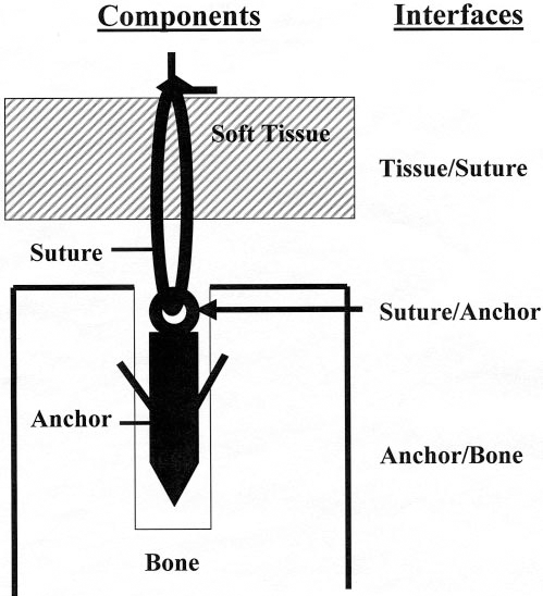
Components and interfaces of soft tissue fixation to bone.
Materials and Methods
Anchors and Sutures
Eight different anchors were tested, both metallic and biodegradable (Fig. 2): GII (Mitek, Norwood, Massachusetts), Super Anchor (Mitek), Statak 5.0 mm (Zimmer, Inc., Warsaw, Indiana), Statak 3.5 mm (Zimmer), Bioanchor (Linvatec Corp., Largo, Florida), Wedge-Tag (Acufex, Andover, Massachusetts), Bio-Statak (Zimmer), and PANALOK (Mitek). A braided polyester suture was used in two different diameters: Ethibond Excel No. 2 USP (Ethicon, Norderstedt, Germany), diameter 0.5 to 0.599 mm and Ethibond Excel No. 5 USP (Ethicon), diameter 0.8 to 0.899 mm.
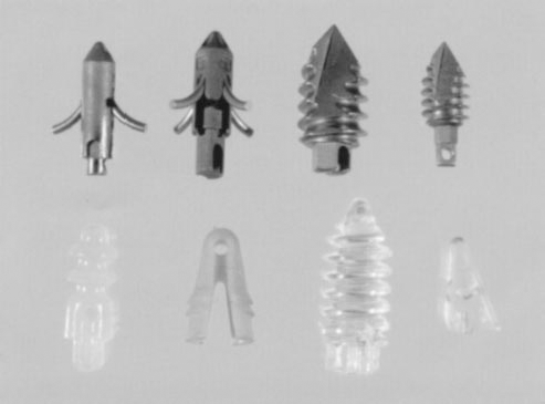
Suture anchors tested. Upper row from left to right: GII, Super Anchor, Statak 5.0 mm, Statak 3.5 mm. Lower row from left to right: Bioanchor, Wedge-Tag, Bio-Statak, PANALOK.
Bone Model
Porcine tibia was used as a bone model because a previous study has shown that the standard deviation of bone density between specimens is very small. 23 The specimens were frozen immediately after harvesting and were thawed for 24 hours at room temperature before testing. Each anchor-suture construct was tested in both cancellous and cortical bone. The medial and lateral tibial plateaus were chosen to represent a cancellous bone environment. After removal of the cartilage, anchors were inserted perpendicular to the articular surface. The anchor positions were spaced at least 1 cm in all directions from their neighbors to prevent propagation of cracks between adjacent drill holes. The lateral surface of the tibial shaft was chosen for anchor insertion to represent a cortical bone environment. As in cancellous bone, the anchor positions were spaced at least 1 cm in all directions from their neighbors. All anchors were inserted according to the manufacturer's instructions using instrumentation specific to each device.
Anchor-Suture Combinations
The two most commonly used anchor types are the nonscrew type (Mitek GII) and the screw type (Zimmer Statak 3.5). Generally, these anchors are threaded with a No. 2 suture. These combinations were used as a benchmark.
Several ways to modify the anchor-suture combination were evaluated to improve the fixation strength (Fig. 3): 1) use of a stronger suture (Ethibond No. 5) with the standard anchor (the use of Ethibond No. 5 suture with a Statak 3.5 anchor was not possible because the eyelet was too narrow); 2) use of better-performing anchors, either a larger metallic anchor or a biodegradable anchor, with an Ethibond No. 2 suture; and 3) use of a stronger suture in combination with a better-performing anchor.
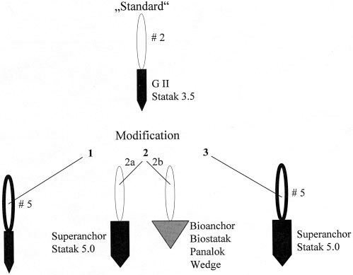
Suture-anchor combinations tested.
Mechanical Testing
Testing was performed on a universal material testing machine (Zwick 1474, Zwick Inc., Ulm, Germany) at room temperature. Two different loading conditions (single pull to failure and fatigue testing) were applied (Fig. 4). All specimens were loaded perpendicular to the surface of the bone.
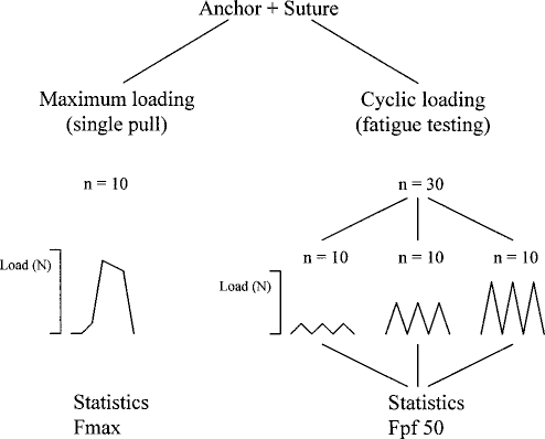
Mechanical testing. Loading conditions and number of specimens for each anchor-suture combination. Fmax, maximum load at failure. Fpf50, load at which the probability of failure is 50%.
Single Pull to Failure (Maximum Loading).
The crosshead speed for the single pull-to-failure test was 250 mm/min. The resulting load-displacement curve was recorded and ultimate load at failure was determined. As a first step, sutures and anchors were loaded independently. Ten specimens of each suture type and 10 specimens of each anchor type were tested. The sutures were knotted around a bar that was attached to the Zwick machine. The first two throws of the square knots were formed from a sliding knot that was tightened and locked by three further throws. The anchors were threaded with steel wire to remove suture breakage as a source of failure. The wires were clamped to the Zwick machine without knotting.
Then anchor-suture constructs were tested. Each group (anchor-suture combination) consisted of 10 specimens. The sutures were knotted around a bar as described. The failure mode was classified into four categories: knot breakage, suture breakage at the eyelet of the anchor, breakage of the anchor, and pullout of the anchor. Statistical analysis was performed using a t-test and a one-way analysis of variance. The level of significance was set at P < 0.05.
Fatigue Tests.
The uniaxial fatigue tests were performed using repetitive loading at a crosshead speed of 250 mm/min. These tests were conducted under load control. Thirty specimens of each anchor-suture combination were tested (Fig. 4). They were divided into 3 test subgroups of 10 specimens each. The applied minimum load was 10 N in all tests. The applied maximum load was set at three different levels individually for each anchor-suture combination on the basis of pretests to produce a spectrum of load ranges appropriate to the mechanical performance of the individual combination (Fig. 5). Weak anchor-suture combinations were submitted to loads lower than those of stronger combinations (Fig. 5). All 10 specimens of one subgroup were submitted to the same maximum load and were tested until failure or 1000 cycles. The ideal loading protocol for an anchor-suture combination would produce nearly no failure on the lowest level, nearly 50% failure on the intermediate level, and nearly 100% failure on the highest level (Fig. 5). Applying the load levels that are appropriate for a weak suture-anchor construct to a strong suture-anchor construct would result in the situation that none or only a few of these specimens would fail (Fig. 5). The resulting database would be too small to calculate a valid load-probability of failure correlation. The accuracy of the mathematical model would be low under these conditions.
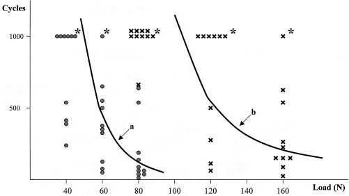
The fatigue life of Mitek GII/Ethibond No. 2 (•) and Mitek Super Anchor/Ethibond No. 5 (×) sutures. The number of cycles until failure is presented as a function of the load applied. The specimens of each group (N = 30) were loaded on three different load levels. Mitek GII/Ethibond No. 2 (•): 10 to 40 N (N = 10); 10 to 60 N (N = 10); 10 to 80 N (N = 10). Mitek Super Anchor/Ethibond No. 5 (×): 10 to 80 N (N = 10); 10 to 120 N (N = 10); 10 to 160 N (N = 10). The asterisks (∗) indicate that the experiment was cut off at 1000 cycles without failure of the construct. From the data of the 30 specimens, the correlation of the number of cycles to load (a for GII and b for Super Anchor) was calculated.
The number of cycles to failure was counted for each specimen. The failure mode was classified into four categories: knot breakage, suture breakage at the eyelet of the anchor, pullout of the anchor, and breakage of the anchor eyelet (biodegradable anchor group only).
The statistical analysis for fatigue testing had to take into consideration the relationship of three parameters: number of cycles, load, and probability of failure. The mathematical model was based on two assumptions: 1) the failure time data most closely follow a Weibull distribution, 26 which is widely used in reliability theory 10 ; and 2) the relationship between load and number of cycles is log linear when censored data are taken into consideration. Censored data are caused by the fact that fatigue testing was cut off at 1000 cycles, even if the specimen would have endured a higher number of cycles. On the basis of these assumptions, the SAS 6.12 procedure LIFEREG 24 (SAS Institute, Cary, North Carolina) was used to fit a parametric model to the failure time data, which allows determination of the number of cycles as a function of load (Fig. 5) and the probability of failure as a function of load (Fig. 6).
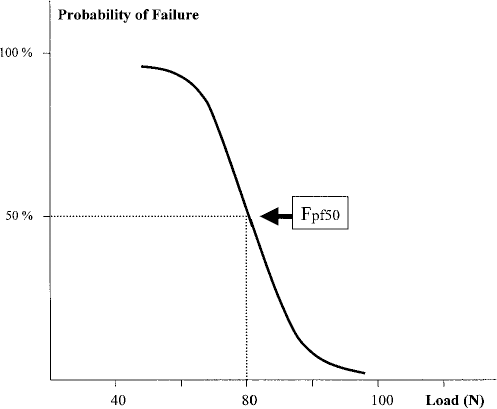
The probability of failure as a function of load. Fpf50 is the load at which the probability of failure is 50% (Mitek GII/Ethibond No. 2).
Comparison of the results of single-pull tests with the results of fatigue tests requires that mean values (load at failure) and probabilities of failure (load at failure) must be compared, which cannot be done directly based on any current statistical method. Under the assumption that the data of the single-pull tests are distributed according to a Gauss distribution, the mean value divides the sample into two subgroups: 50% of the specimens failed at loads higher than the mean value and 50% of specimens failed at loads lower than the mean value. Under these assumptions, the mean value (maximum load at failure) indicates the load at which 50% of the specimens failed; in other words, the probability of failure is 50%. The load-probability of failure correlation was calculated from the fatigue-testing data. The load at which the probability of failure is 50% was assessed (Fig. 6). At this load, one-half of the specimens would fail during fatigue testing. This load (Fpf50) is comparable to the mean value of the maximum load at failure determined in single-pull tests.
Results
Sutures
The maximum load at failure was 129.2 (12.4) N (mean and standard deviation) for Ethibond No. 2 and 244.4 (15.0) N for Ethibond No. 5 suture. Under cyclic loading conditions, the probability of failure was 50% at 104.6 N for Ethibond No. 2 and at 193.9 N for Ethibond No. 5.
Anchors
The maximum pullout strength for the anchors tested is given in Table 1. When metallic anchors were inserted in cancellous bone, the mean primary fixation strength ranged from 194 N (GII) to 327 N (Statak 5.0). Most anchors performed better when inserted in cortical bone; the mean load at failure ranged from 203 N (GII) to 525 N (Super Anchor). Most biodegradable anchors had significantly lower pullout strength compared with metallic anchors.
Maximum Loading Strength (in Newtons) of Metallic Anchors and Biodegradable Anchors Threaded with a Steel Wire and Inserted in Cancellous or Cortical Bone
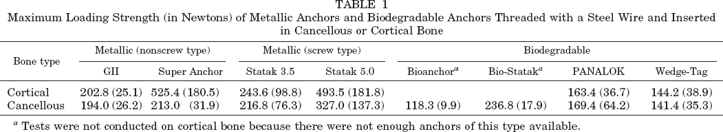
Tests were not conducted on cortical bone because there were not enough anchors of this type available.
Suture-Anchor Constructs
Maximum Loading.
Threading the anchors with sutures instead of steel wire resulted in different fixation strengths (Table 2). In most combinations with Ethibond No. 2, the suture was the weakest link. Most failures were the result of breakage of the knot or breakage of the suture at the eyelet. This was predictable from the fact that the maximum failure load of Ethibond No. 2 was 129 N, which is significantly lower than the fixation strength of most anchors tested (Table 1). Anchor pullout or failure was seen for the GII (10% in cancellous bone), the Bioanchor (40% in cancellous bone), and the PANALOK anchors (50% in cancellous bone).
Maximum Loading until Failure of Anchors Threaded with Sutures
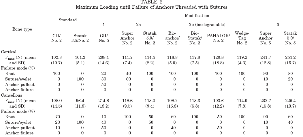
The maximum failure load of Ethibond No. 5 suture was in the range of the fixation strength of the standard metallic anchors (GII) but below the fixation strength of the Super Anchor and the Statak 5.0. In these anchor-suture combinations (Ethibond No. 5/Super Anchor or Statak 5.0) the maximum failure load of the suture determined the fixation strength of the construct in most cases. For example, the mean ultimate load at failure for the combination Statak 5.0/Ethibond No. 5 was 251 N, compared with 493 N when the Statak 5.0 was tested with a steel wire in cortical bone. In combination with the GII anchor in cancellous bone, the anchor and the Ethibond No. 5 suture were equal in failure, resulting in 50% suture failure and 50% anchor pullout.
Fatigue Testing
Standards.
Under cyclic loading conditions, the 50% probability of failure was reached at loads that were below the mean maximum load at failure determined in single-pull tests (Tables 2 and 3). The anchor-suture interface was identified as the weakest link of the GII/No. 2 combination and of the Statak 3.5/No. 2 combination in cancellous bone and in the cortical bone environment. In most cases, the suture was worn through at the eyelet. Because of this failure mode, the fatigue strength of the constructs was below their maximum strength.
Fatigue Testing of Anchors Threaded with Sutures
Load at which the probability of failure is 50%.
Modification 1 (No. 5 Suture).
Threading the GII anchor with a No. 5 suture increased the fatigue strength if the anchor was inserted in cortical bone. Because of a 75% failure rate at the eyelet, the fatigue strength of the construct was below the fatigue strength of the No. 5 suture. If the anchor was inserted in cancellous bone, the fatigue strength was not increased to the same extent because the fixation strength of the GII anchor in cancellous bone was the weak link under cyclic loading. Consequently, the predominant failure mode was the pullout of the anchor (Table 3).
Modification 2a (Super Anchor, Statak 5.0).
Using larger anchors in combination with the No. 2 suture increased fatigue strength because of a less-detrimental anchor-suture interaction at the eyelet. For the Super Anchor/No. 2 construct, a shift of the predominant failure mode to a breakage of the knot was obvious (Table 3). For the Statak 5.0/No. 2 combination, most failures occurred at the suture attachment but at higher loads. The increase in fatigue strength was due to a “smoother” anchor-suture interface and not to better fixation strength of the anchor in the bone.
Modification 2b (Biodegradable Anchors).
With use of biodegradable anchors inserted into cortical bone, suture breakage at the knot was the predominant failure mode. The anchor-suture interface had no effect on the fatigue strength, which was near the fatigue strength of the suture material and higher than the fatigue strength of standard combinations. When the anchor was inserted in cancellous bone, with three of four anchors tested, anchor pullout was the predominant failure mode. The fatigue strength of the construct decreased compared with the cortical bone environment and was below the strength of the suture material.
Modification 3 (Stronger Suture in Combination with a Better-Performing Anchor).
The highest fatigue strength was seen for the Super Anchor/No. 5 combination when the anchor was inserted into cortical bone. The fatigue strength of the construct did not differ from the fatigue strength of the No. 5 suture. When this construct was inserted in cancellous bone, the anchor-bone interface determined the fatigue strength, which was below the fatigue strength of the No. 5 suture. Anchor pullout was the predominant failure mode.
Discussion
Most of the studies evaluating suture anchors have used a single-pull load to failure. However, cyclic loading better represents the repetitive movements of joints during rehabilitation and in daily activities after surgery. Only a few articles have addressed the fatigue strength of these devices.
Berlet et al. 4 evaluated the Mitek Super Anchor and the Zimmer Statak 5.2 mm anchor inserted in human cadaveric radii. A No. 5 Ti-Cron suture (Ethicon, Inc., Somerville, New Jersey) was threaded through each anchor. The cyclic loading was applied as a sinusoidal pattern between 0 and 50 N for 3600 cycles. None of the anchors failed.
Burkhart et al. 5 performed cyclic loading of rotator cuff repairs in human cadaveric shoulders in which Mitek RC anchors and three simple sutures had been used for each repair. Each specimen was cyclically loaded to 180 N at a rate of 33 mm/sec. The specimens reached 50% failure (5-mm gap) at an average of 61 cycles and 100% failure (10-mm gap) at an average of 285 cycles. Fifteen of 16 specimens failed through the tendon. The simple stitch type of suture does not have a strong hold in the tendon, as shown by Gerber et al. 7 In combination with the relatively strong anchor, the suture-tendon interface is the weakest link. These data emphasize that the suture-tendon interface may have an important role in the mechanics of soft tissue fixation. However, they also show that it is necessary to exclude the soft tissue from the experimental model if the focus is on evaluation of the anchor-suture interaction.
Roth et al. 22 tested the Mitek GII anchor and the Zimmer Statak 3.5 anchor inserted into human cadaveric glenoids. The anchors were threaded with steel spring wire. The study was focused exclusively on the anchor-bone interaction. The anchors were cycled at 2 Hz with a sinusoidal loading pattern between preselected minimum and maximum loads. For the initial tests, the maximum load was set to 350 N. For the subsequent tests, it was incrementally lowered between each test until 10% of all anchors survived at least 50,000 cycles (the smallest maximum load was 30 N). The fatigue life of each anchor was highly dependent on the magnitude of the load applied and the cortical thickness at the implantation site. A dramatic decrease in fixation strength occurred within the first 100 cycles, and the maximum load that should be applied to reach a life of 1000 cycles was less than 50% of the theoretical ultimate pullout strength. The authors published a similar study of the Mitek GII anchor earlier. 27
Rossouw et al. 21 investigated the Mitek GII anchor in combination with an Ethibond No. 2 suture for repair of the rotator cuff. Seven human cadaveric shoulders were used for the cyclic-load tests. The anchors were placed in the lateral cortex of the humerus, directed 45° caudally. A 30-mm defect was created. Each reconstruction consisted of two modified Snyder sutures with an anchor. Two supplementary horizontal mattress sutures were placed across the surface of the tendon and passed through the bone of the greater tuberosity, where they were knotted, so that eight suture strands crossed each repair. Ten load cycles from 0 to 50 N were applied at 50 mm/min. The maximum force was then increased to 100 N for 10 cycles and by 50 N for each subsequent set of 10 cycles until failure. Ultimate failure occurred at 227 ± 41 N by breakage of the suture at the knots and suture anchors. After the 100-N increment (a total of only 20 load cycles), there was a permanent deformation of 6.7 ± 1.8 mm. Strictly speaking, this should be judged as fixation failure. The fatigue strength of this construct was above the fatigue strength of the No. 2 suture because of the eight suture strands. A problem with testing whole constructs becomes obvious. It is problematic to have defined loading conditions for each component of the fixation complex and to assess each component independently.
The fatigue characteristic of any surgical fixation method is an important mechanical property. To determine the fatigue behavior, a valid test method and a statistical concept is mandatory. Krause et al.13–15 introduced the concept of the probability of failure and connected it with the well-known data of stress versus the number of cycles to failure for describing the fatigue properties of acrylic bone cement. The objective of the present study was to adapt the basic ideas of this concept to the special needs of fatigue testing of suture-anchor fixations. The model used in this study is based on principles of reliability theory. 10 The data include the estimation of the probability of failure in relation to the number of cycles and in relation to the load.
The soft tissue fixation to bone with suture anchors creates a complex composite of different components or tissues and different interfaces with different mechanical properties (Fig. 1). The mechanical performance of the whole construct evaluated in this study is determined by the relationship of two parameters: the pullout strength of the anchor inserted into a defined bony environment, which depends on the anchor configuration and the local bone quality, and the strength of the suture material and the anchor-suture interaction, which depends strongly on the material, configuration, and surface of the eyelet. The weakest link limits the performance of the composite.
In this study, we did not evaluate the suture-soft tissue interface, which may have an additional effect on the fixation strength of soft tissue to bone in vivo.5,7 The mechanical behavior of this interface depends strongly on the soft tissue structure and quality, the diameter of the suture, and the tissue-grasping technique. This part of the construct has no direct influence on the anchor-suture interaction or on the anchor-bone interaction. Therefore, we decided to evaluate this aspect separately using human tissue.
Whereas the anchor-bone interaction depends strongly on the anatomic and mechanical conditions at the insertion site, such as thickness of the cortical bone layer or density of the cancellous bone,1,8,22 the strengths of the suture and the suture-anchor attachment are independent of these factors and widely constant for any location. Thus, we can determine the theoretical maximum fixation strength of an anchor-suture combination, provided the tissue-suture interface and the anchor-bone interface are stronger.
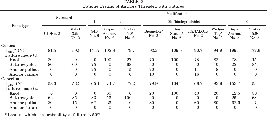
We are aware of the fact that in many clinical situations anchors are not inserted perpendicular to the surface of the bone. In this experimental study, the anchor-suture constructs were loaded along the axis. The perpendicular type of insertion was chosen to create reproducible loading conditions and to minimize bias. This model represents the worst case with respect to the pullout force of the anchors but the best case with respect to the anchor-suture interface. An angle between the drill hole and the bone surface may result in a contact between the suture and the edge of the drill hole. The eyelet-suture interaction depends on the alignment of the anchor in relation to the suture and the load axis. The eyelets of the anchors are not symmetric in all models. Figure 7 shows an eyelet that is rounded only at its tip to accommodate the suture. If there is an angle between the anchor and the suture, the suture may have contact with the edges of the eyelet. The main interest in this study was the suture-anchor interface. The fact that the loading axis was parallel to the axis of the anchors may result in underestimating the effects of suture-anchor interaction at the eyelet. However, it should be clear that the data concerning the bone-anchor interface are valid exclusively for the bone model used and cannot easily be transferable to other situations.
A microscopic view of the eyelet of a GII anchor (Mitek).
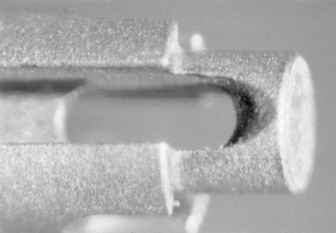
The loading conditions have a significant effect on failure loads and failure modes. In a single pull-to-failure test, the No. 2 suture was the weakest part in most combinations. The construct failed at the maximum strength of the suture material. In this setting, the pullout strength of the anchor did not determine the performance of the system as long as it was higher than the strength of the suture material threaded through the anchor. Under cyclic loading, the anchor-suture interface gains an important role. The eyelets of the metallic anchors tested had a rough surface and sharp edges (Fig. 7). The suture was worn through at the eyelet in a high number of tests. Because of this mode of failure, the fatigue strength of the anchor-suture combination was significantly below the fatigue strength of the suture material. In contrast, the eyelet of the biodegradable anchors was smooth (Fig. 8). The predominant failure mode was the suture breakage at the knot, resulting in fatigue strength comparable to the fatigue strength of the suture material itself.
A microscopic view of the eyelet of a PANALOK anchor (Mitek).
Even if the suture material is the weakest link, the performance of the anchor-suture combination can differ significantly. In combination with a suture instead of a steel wire, an anchor with inferior pullout strength may perform better under cyclic loading than an anchor with higher pullout strength. For example, in cortical bone, the Statak 5.0 anchor provided a superior pullout strength compared with the PANALOK anchor (493 N compared with 163 N). Combined with a No. 2 suture, both constructs performed equally under single-pull loading (114 N compared with 120 N). However, under cyclic loading the combination PANALOK/Ethibond No. 2 showed superior fatigue strength (90 N) compared with the Statak 5.0 (79 N).
The two most commonly used anchor types are the nonscrew type (Mitek GII) and the screw type (Zimmer Statak 3.5). Generally, these anchors are threaded with a No. 2 suture. These combinations were used as a benchmark. There are two principal ways to improve the standard. First, the attachment of the suture to the anchor can be improved. The eyelet should have a smooth surface, and sharp edges should be avoided. The prototypes of this approach are the biodegradable devices. The effect of using larger anchors (such as the Mitek Super Anchor) with larger eyelets is partly due to a less suture-damaging anchor-suture interaction. In combination with the No. 2 suture, the superior pullout strength of these anchors was not relevant in the bone model used in this study.
The second way to improve the mechanical performance of the tissue fixation to bone is to use stronger sutures. In combination with the No. 5 suture, the site of failure was shifted more to the anchor. Under single-pull loading, 50% of the Mitek GII anchors pulled out. This was because the pullout strength of the GII anchor inserted into the cancellous bone of the porcine tibia matched the tensile strength of the Ethibond No. 5 suture material. Under cyclic loading, the anchor turned out to be the weakest link when inserted in cancellous bone, whereas the anchor-suture interaction determined the fatigue strength of the combination when the anchor was inserted in cortical bone. The fatigue strength was significantly different (65 N in cancellous bone versus 141 N in cortical bone).
Conclusions
Knowledge of the maximum pullout strength of different suture anchors may be helpful to avoid complications. It may be advantageous to use an anchor with high pullout strength to avoid failure by anchor pullout. However, to evaluate suture anchors, fatigue testing is crucial because this method of loading represents conditions closer to those in vivo than does single-pull testing. Cyclic loading yields results that do not match the maximum failure loads.
The mechanical performance of a suture anchor threaded with a suture depends on several key factors that are not necessarily in a constant relationship: pullout strength of the anchor, which is mainly a result of anchor configuration and bone quality and which can differ depending on anatomic localization and the age of the patient; the tensile strength of the suture; and the interaction of anchor and suture at the eyelet (suture-anchor interface). In vivo, the pullout strength of the suture in soft tissue is an additional key factor, depending mainly on the suture material and diameter, tissue quality, and the tissue-grasping technique. 7 The weakest link within the whole construct determines the mechanical performance of the fixation. Improvement of fixation techniques with respect to failure strength can only be reached by reinforcing the weakest link. The attachment of the suture to the anchor and the strength of the suture material deserve more attention. Fatigue strength can be improved with use of stronger sutures and anchors with smooth eyelets that reduce the risk of damage to the suture during repetitive loading.