
Abstract
Abstract: Meniscus replacement by a polymer meniscus prosthesis in dogs resulted in generation of new meniscal tissue.
Hypothesis: Optimal functioning of the prosthesis would involve realistic deformation and motion patterns of the prosthesis during knee joint motion.
Study Design: Controlled laboratory study.
Methods: The movements of the meniscus were determined during knee joint flexion and extension with and without internal and external tibial torque by means of roentgen stereophotogrammetric analysis. Subsequently, the meniscus in 6 human cadaveric knee joints was replaced by a meniscus prosthesis.
Results: All different parts of the meniscus showed a posterior displacement during knee joint flexion. The anterior horn was more mobile than the posterior horn. The prosthesis mimicked the movements of the meniscus. However, the excursions of the prosthesis on the tibial plateau were less. The knee joint laxity was not significantly higher after replacement with the meniscus prosthesis.
Conclusions: The prosthesis approximated the behavior of the native meniscus. Improvement in both the gliding characteristics of the prosthetic material and the fixation of the prosthesis may improve the function.
Clinical Relevance: The meniscus prosthesis needs to be optimized to achieve a better initial function in the knee joint.
The knee joint menisci are wedge-shaped semilunar disks interposed between the tibia and the condyles of the femur. The distal surface is convex and rests on a relatively flat tibial plateau, whereas the concave proximal surface of the meniscus deepens the articular fossae of the tibia to create more congruity with the femoral condyles.9,14 To retain this congruity during knee joint flexion, the whole meniscus moves posteriorly on the tibial plateau to accommodate the femoral rollback on the tibial plateau, and, in particular, the anterior horn shows great displacements to stay in close contact with the declining diameter of the femoral condyles.9,18,20 In this manner, the meniscus stabilizes the knee joint and contributes to load bearing and shock absorption. 14
Meniscal injuries are commonly diagnosed in today's orthopaedic practice. Only a few decades ago, it became clear that total meniscectomy leads to articular cartilage degeneration, and from then on, it has generally been recognized that the amount of meniscal tissue removed should be minimized or repaired.8,10,13,16 These degenerative changes are directly proportional to the amount of meniscus removed. 6 In many cases, however, the large extent of meniscus damage makes a total or partial meniscectomy inevitable. In these cases, prosthetic replacement of the resected meniscal tissue may be a viable technique to avoid articular cartilage degeneration. Former and current studies in dogs show that a meniscus prosthesis made of a biodegradable porous polymer can act as a temporary scaffold for the regenerating tissue. 12 When implanted in a canine knee, ingrowth of fibrovascular tissue into the prosthesis occurred, the tissue differentiated into meniscal fibrocartilage, and degenerative changes of articular cartilage were less compared to the postmeniscectomy knee. In this dynamic biological process, the new meniscal tissue may be able to adjust to the functional requirements of the surroundings to which it is subjected in the long term. Before these biological interactions, however, the prosthesis should already mimic the behavior of the native meniscus directly after implantation. Therefore, material characteristics of the prosthesis, such as stiffness, tear strength, and gliding capacity, are a great influence on the performance of the synthetic prosthesis. Furthermore, size and fixation of the prosthesis may also be very important, as stated in meniscal allograft transplantation studies.1,2,15
To compare the behavior of the prosthesis in the knee joint with that of the native meniscus, an in vitro model was developed according to Blankevoort et al. 4 In this model, the movement of the native meniscus and the prosthesis could be evaluated successively within the same cadaveric knee joint.
Aim of the Study
The purpose of this study was to determine how close the prosthesis mimicked the functional behavior of the native meniscus. Therefore, the displacements of the native meniscus and subsequently those of the prosthesis were measured during knee joint flexion in cadaveric knee joints with and without an additional tibial torque.
Materials and Methods
Six fresh knee joints (3 female and 3 male knee joints, cadavers aged 68-92 years) were obtained from autopsy and kept frozen until the time of use. At manual and arthroscopic examination of the 6 knees, no abnormalities were found in soft tissue, bony structures, ligaments, or menisci.
The bones were transected approximately 15 cm above and 15 cm below the joint line. The tendon of the rectus femoris muscle was left intact for joint loading. All soft tissues, including the skin, were left intact. Five tantalum beads (0.8-mm diameter) were fixed into the cortex of the tibia and femur. Under arthroscopic control, 3 beads were inserted through the capsule in the periphery of the medial meniscus by means of an insertion device, which placed the beads at 10 mm from the peripheral side of the knee joint capsule into the meniscal stroma (Figure 1).
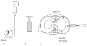
Schematic view of the insertion device and procedure of insertion of the beads into the meniscus. Beads were placed in the insertion needle (a), and the needle was again placed into a device (b), which secured an insertion depth of 10 mm in the meniscal stroma through the knee joint capsule. As shown in (c), 3 beads of 0.8-mm diameter were inserted under arthroscopic control.
Each specimen was then fixed in a specially developed motion and loading apparatus (Figure 2), 4 allowing the tibia movement in 6 degrees of freedom relative to the femur. Flexion of the knee joint (axis 1) was performed by changing the angle of the femur relative to the tibia. This flexion angle was prescribed in steps of 5 The other 2 rotation axes of the apparatus were tibial rotation (axis 3) and varus-valgus rotation (axis 4), of which flexion and varus-valgus rotation occur in mutually perpendicular planes. Axial translation (axis 6) was possible through a 4-bar linkage mechanism on the femoral side. The anterior-posterior (AP, axis 2) and medial-lateral (ML, axis 5) translations were possible via rotations around 2 axes located distally on the tibial side, relatively far from the joint.
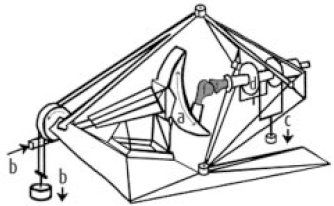
Knee joint loading apparatus. On the left side is the femur (f), which is rigidly affixed to the semilunar device (a). Different knee joint flexion angles are realized by rotating the semilunar device, thereby changing the angle of the femur relative to the tibia (t), as indicated in (a). The axial load (b) is applied to the femur. On the right side is the tibia. On this side of the apparatus, the degrees of freedom of joint motion are internal and external rotation, varus-valgus rotation, medial-lateral translation, and anterior-posterior translation. Internal and external torques (d) were applied through a pair of sheaves (c).
Loading of the knee was realized by applying weights to those parts of the apparatus that corresponded with the respective motions. The axial force (200 N) (Figure 2) and a pulling force on the rectus femoris muscle tendon (90 N) were applied through a pair of pulleys and wires at the femoral side of the loading apparatus, where the flexion mechanism was located. Consequently, for each specific flexion angle prescribed, the axial force was applied on the femur but remained directed approximately along the tibial axis. The limits of internal and external tibial rotation were defined at torques of 3 N m, which were applied through a pair of sheaves on the tibial side. The motion pathway along these limits was defined as the envelopes of passive knee joint motion, as described by Blankevoort et al. 4 Beyond these limits, damage to the knee joint might occur. It must be stressed that the apparatus was designed to accommodate passive range of knee joint laxity at moderate loading, rather than to test knee joint behavior at high loads.
The loading apparatus was positioned at 60 cm from the film cassette and at 100 cm from the roentgen tubes. The distance between the roentgen tubes was 120 cm (Figure 3). Biplanar roentgen exposures were made as shown in Figure 3.
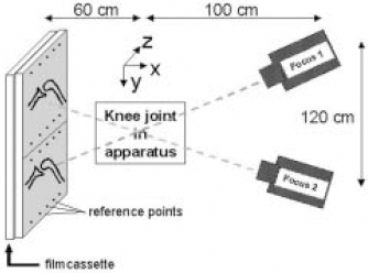
Positioning of the loading apparatus, the roentgen tubes, and the film cassette. Two separate images were taken with 2 tubes on the same roentgen film. Note the reference points on the film cassette and the positioning of the knee joint in the coordinate system: the x-direction represents medial-lateral displacements on the tibial plateau, and the z-direction represents the anterior-posterior displacement on the tibial plateau.
Each knee was tested without tibial torque, with internal tibial torque, and with external tibial torque in different degrees of flexion (0, 15, 30, 60, 90, 60, 30, 15, 0, respectively). At each flexion position, 2 roentgen exposures of the bones and meniscus with the beads were taken.
The roentgen exposures were evaluated on a 2-dimensional digitizer (Aristo 104-S, equipped with an Aaton video camera, Holland Equipment, Coatesville, Pa), measuring the marker images (accuracy of 20 m m according to the descriptions of the manufacturer). A computer program calculated the kinematic parameters, which described the finite motions in z-axis (AP direction) and x-axis (ML direction), of different parts of the meniscus during flexion of the knee joint.
Then, the movements of the beads between their location at 0 of knee joint flexion and the actual location at the different flexion angles were determined and defined as “displacement.” The “pathway” was defined as the route on the tibial plateau during knee joint flexion and extension.
As described by Blankevoort et al, the rotation of the tibia relative to the femur increases as a result of tibial torque during knee joint flexion. 4 The degree of tibial rotation relative to the femur, and thus the outer limits of internal and external tibial rotations, can be measured as a degree of the knee joint laxity.
Prosthetic Material
The meniscus prostheses consisted of biodegradable aromatic urethanes based on Estane (5701-F1, BF Goodrich Chemical, N. V. Westerlo-Oevel, Belgium). Macropores were created, as described in an earlier study, 7 by mixing the polymer solvent solution with salt crystals ranging in size from 150 m m to 355 m m. Freeze-drying the solvent created micropores of at least 30 m m. Porosity was 80%. The compression modulus was 200 kPa.
Meniscal Transplantation
We performed an arthrotomy via a medial parapatellar incision of the skin and performed a bony release of the medial collateral ligament (MCL) from its insertion at the medial epicondyle of the femur. By turning down the ligament, an exposure of the joint was obtained. Then, the medial meniscus was excised. One drill hole was made in the posteromedial side of the proximal tibia, ending in the posterior area of the intercondylar eminence (Figure 4). One monofilament nonabsorbable suture was attached to the properly sized porous polymer meniscus prosthesis and was pulled through the drill hole. The anterior horn and entire peripheral rim of the prosthesis were sutured to the capsule using vertical 2-0 absorbable braided sutures. The MCL was reattached at its insertion on the epicondyle using a 3.5-mm trabecular screw. The capsule and skin were closed, and 20 mL of saline solution was injected in the joint space. Then, the same test procedure as for the native meniscus was performed.
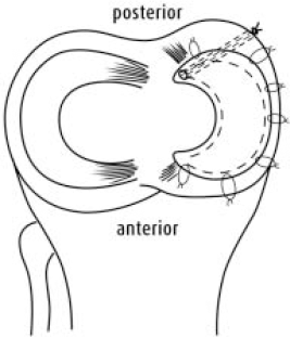
Schematic presentation of the surgical procedure. After resection of the native meniscus, 1 drill hole (dotted line) was created originating from the posterior tibial side to the former attachment of the posterior horn of the native meniscus. Subsequently, a monofilament suture was pulled through the posterior horn of the prosthesis and attached to the tibia. The periphery of the prosthesis was attached to the capsule with 2-0 resorbable braided sutures.
After the experiments, the joint was dissected, and the most posterior insertion of the ACL on the tibia was marked with an additional tantalum bead to define the origin of the coordinate systems in extension.4,19
Data Analysis
Univariate analysis of variance tests were applied for statistical analysis of the displacements of the different meniscal beads with respect to the beads in the tibia. Each specimen served as its own control to study the effects of internal and external tibial torque relative to the position of the bead at zero rotational torque. The knee joints and the knee joint flexion angles were determined as independent variables and the displacement of the different parts of the meniscus and the prosthesis as dependent variables. Any interactions between the flexion angle and the tibial torque were also determined. Statistical significance and correlation were set at P < .05.
Results
Without Tibial Torque
During flexion, all menisci and prostheses moved in the posterior direction (Figure 5). In both AP and ML directions, the displacement of the prosthetic anterior horn was smaller than that of the meniscus (for AP, P = .023; for ML, P = .03). In the AP direction, the prosthetic posterior horn showed a trend to displace less than in the native meniscus (P = .059). In the ML direction, all parts of the menisci and the prostheses showed less movement than in the AP direction. The maximal displacements of the meniscal and prosthetic posterior horns did not differ significantly (Figure 6).
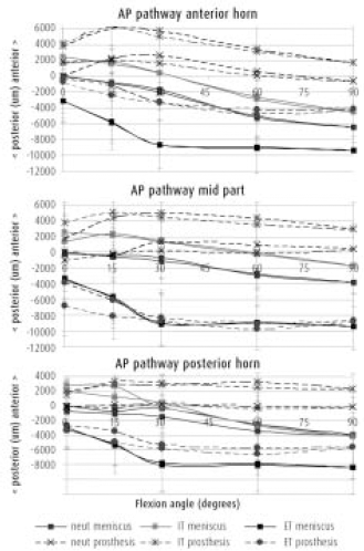
Pathways of the different meniscal and prosthetic parts in anterior and posterior directions on the tibial plateau. Both with tibial torque and without tibial torque (neut), the slope of the curves of the prosthesis is less steep than that of the meniscus, resulting in less displacement on the tibial plateau. AP, anterior-posterior; IT, internal tibial torque; ET, external tibial torque.
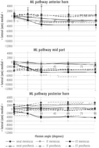
Pathways of the different meniscal parts in medial and lateral directions on the tibial plateau. Both the meniscus and the prosthesis showed evidently less displacement in the medial-lateral (ML) direction than in anterior-posterior displacements. Only in the menisci were more displacements observed during external tibial torque (ET). Neut, without tibial torque; IT, internal tibial torque.
Maximal posterior displacement was reached at 90 of knee joint flexion. The anterior horn of the meniscus showed significantly greater maximal posterior displacements (mean, 6.4 mm) than its posterior horn (3.2 mm, P < .001). The displacements of the prosthetic horns were smaller (anterior horn of the prosthesis, 0.6 mm; posterior horn, 0.2 mm; P = .410). In the ML direction, the displacement of the native meniscal anterior horn was not significantly greater than the posterior horn (mean, 1.8 mm and 0.2 mm, respectively).
Internal Tibial Torque
When internal tibial torque was applied to the knee joint, the pathways of all different meniscal parts shifted anteriorly on the tibial plateau. Subsequently, all parts of the menisci and prostheses again moved in a posterior direction on the tibial plateau during knee joint flexion. This shift was significant only for the anterior horn, compared to the situation in neutral knee joint flexion (P < .001). The anterior horn of the meniscus showed a parallel pathway with and without internal tibial torque. The same trend was observed for the middle zone and posterior horn. No significant interaction was observed between the flexion angle of the knee and the internal tibial torque on the posterior displacement of the meniscus. The displacement of the anterior horn was more than the displacement of the posterior horn (P < .001). Maximal displacement was reached at 90 of flexion. The average displacement of the meniscal anterior horn was 2.2 mm in the lateral direction, whereas the average displacement of the posterior horn was 2.4 mm in the opposite medial direction.
The prosthesis showed the same behavior after applying internal tibial torque. The pathway of the prosthetic anterior horn remained more anteriorly on the tibial plateau than the pathway of the meniscus (P = .036, P = .003, and P < .001 for the anterior horn, middle zone, and posterior horn, respectively). Also during internal tibial torque, all different parts of the prosthesis were evidently less mobile than the parts in the meniscus.
In the ML direction, the posterior horn in the meniscus and in the prosthesis did not show any displacement. The anterior horn and middle zone in the meniscus showed more displacement than in the prosthesis (P < .001 and P < .003, respectively).
External Tibial Torque
The pathway of all different meniscal parts was located significantly more posteriorly and laterally on the tibial plateau than during neutral knee joint flexion (Figures 5 and 6). In all 3 parts of the meniscus, the displacement of the meniscus reached a plateau phase at 30 of knee joint flexion, which suggested an interaction between the flexion angle and the tibial torque. This was confirmed statistically (P < .001). There were no significant differences between displacements of the anterior and posterior horn.
As during the absence of tibial torque, the prosthesis again showed less displacement than the native meniscus. The anterior horn of the meniscus, in particular, was more mobile in the posterior and lateral directions than in those of the prosthesis (P = .010 and P = .013, respectively).
Also, the prosthesis showed a similar interaction pattern between the flexion angle of the knee joint and the displacements. Again this was confirmed statistically (P = .006 and P = .034 for the anterior and posterior horn, respectively).
Laxity
Minimal laxity was found at a knee flexion angle of 0 in all knees (Figure 7). Maximal increase of laxity was observed during the first 30 of flexion, which remained to be observed after implantation of the meniscal prosthesis.
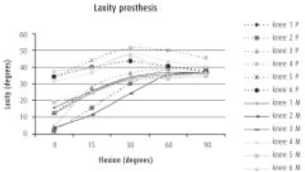
Tibial rotatory laxity of the different knee joints as a function of flexion. In most knees, maximal laxity was observed at 90 of flexion. Knee joint laxity tended to be lower after implantation of the prosthesis (P, dashed curves) than with native meniscus (M) still in situ.
Although less steep, laxity increased during further flexion in the knees with the native meniscus and reached a maximum at 90 of flexion in all knees, except for 2 cases (knees 4 and 6), which reached their maximum at 60 After implantation of the meniscal prostheses, the laxity of the knee was not significantly different (P = .304, univariate ANOVA).
Discussion
In this study, the displacements of the meniscus prosthesis on the tibial plateau were quantified and compared with the behavior of native meniscus during knee joint flexion. To compare the function of the prosthesis with that of a native meniscus within the same knee, an in vitro model was developed with an accurate measurement system for 3-dimensional kinematics and a loading and motion apparatus. With the provided data, we were able to reconstruct the meniscal and prosthetic behavior on the tibial plateau.
The meniscus prosthesis was made of biodegradable Estane. The characteristic porosity, pore sizes, and biomechanical properties of this polyesterurethane proved to be appropriate for ingrowth and regeneration of new meniscal tissue in animal studies.11,12 Also, in the present study, the polymer material could easily be modeled into the specific shape of the medial meniscus, and the material provided a high tear strength, which made it strong enough for suturing into the peripheral capsule and fixation of the horns on the tibial plateau.
Similar to previous studies,9,18,20 the present study showed that all parts of the native meniscus moved posteriorly on the tibial plateau during knee joint flexion. These studies suggest that the femoral condyles move in the same direction during flexion; it may be assumed that the meniscus stays in close contact with the femoral condyles, thereby maintaining a large contact surface between the femoral condyles and the tibia. The meniscus prosthesis also showed a posterior movement on the tibial plateau. This finding suggests that because of its form and its fixation in the knee joint, the prosthesis was forced to stay in contact with the femoral condyles during knee joint flexion, as is the case with native meniscus. However, the degree of displacement with the prothesis was less, resulting in a smaller displacement at 90 of knee joint flexion. Also, during flexion with addition of rotational tibial torque, the prosthesis showed less displacement than the native meniscus. This tendency could negatively influence the congruity between the prosthesis and the femoral condyles, which again may decrease the function of the prosthesis. However, prosthesis function may improve on the longer term in vivo during the infiltration of tissue into the porous material. As stated before, animal studies showed cartilage-like tissue formation in the prosthesis, which might improve the gliding capacity of the prosthesis and thereby its displacements.
The relatively mobile anterior horn seemed to be responsible for making adjustments to the decreasing diameter of the femoral condyle during knee joint flexion.9,17,18,20 This was confirmed in the present study, in which the anterior horn of the meniscus showed more AP displacement than the posterior horn. In the prosthesis, however, no difference was observed between displacement of the anterior and posterior horn. The fixation of the implant, in our view, may play a dominant role. In the anatomical situation, the anterior horn fixation is realized by the combination of partly the attachment to the anterior capsule, the transverse ligament, and the attachment on the tibial plateau. 3 This combination may enable the anterior horn to move more in an AP direction than in a ML direction. Therefore, we decided to attach the anterior horn of the prosthesis only to the anterior capsule to achieve maximal mobility without a chance of dislocation of the horn. Because of this attachment, however, full adjustment of the anterior horn to the posterior movement and decreasing diameter of the femoral condyles might not have been possible. Therefore, in future experiments, fixation of the anterior horn on the tibial plateau may be preferable. The posterior horn of the native medial meniscus firmly attaches to the posterior intercondylar fossa and is integrated into the different layers of the posterior capsule—this combination functionally leads to restricted movements of the posterior horn. 14 Based on the anatomical situation, the posterior horn of the prosthesis was affixed to the tibial plateau and sutured into the posterior knee joint capsule. This fixation was probably too rigid, which impaired the movement of the prosthetic posterior horn.
The material characteristics of the polymer prosthesis may also have influenced the movement on the tibial cartilage. Because of its porous structure, the bare polymer initally affects the gliding surface on the surrounding tibial and femoral articular cartilage. The absence of synovial fluid after an arthrotomy does not improve this situation. The initial performance may be improved by injection of an elastic and viscous hyaluron base fluid. This lubricant can at least temporarily replace the synovial fluid lost after surgery. 5
In the absence of the ACL, the menisci have been shown to enhance the stability of the knee in the AP, varus-valgus, and internal-external directions in vitro. 17 Although the menisci transmit load, they do not contribute to the primary stability of the knee when the ACL is intact. 13 Nevertheless, determining the laxity of the knee joint before and after replacement of the native meniscus provided information about the consequences of the meniscus prosthesis on knee joint function. In the first flexion angles, there was no difference in knee joint laxity between native meniscus and prosthesis. However, although not significant, the laxity of the different knee joints with prosthesis seemed to be higher at higher flexion angles than in the knees with the native meniscus in situ. This difference may imply that with the same tibial torques, greater internal and external tibial rotations would be possible after implantation of a meniscus prosthesis. This finding suggests a minor contribution of the prosthesis to the restraint of knee joint motions. However, sham operations were not performed, and thus we cannot exclude that this increase in laxity was evoked by the arthrotomy and the release and reattachment of the MCL from the epicondyle during the implantation of the prosthesis. With the beads in the femur and tibia, it would be possible to determine the influence of the implantation procedure on the kinematics of the knee joint itself. These factors may be subjects for future investigation.
In this phase of the research project, we decided to implant the prosthesis by means of arthrotomy to enhance the exposure and to ensure a good fixation of the prosthesis in the joint. Arthroscopic implantation probably would do less harm to the capsule of the knee joint and therefore would have less influence on the laxity. Furthermore, the chances of clinical implementation of this procedure would also be increased with arthrosopic implantation. In the next phase, we intend to implant the prosthesis arthroscopically.
In this in vitro model, the performance of a meniscus prosthesis could be assessed and compared to the behavior of the native meniscus on the tibial plateau in a very accurate manner, using the same knee. All different parts of the meniscus showed a posterior displacement during knee joint flexion, this pathway showing an anterior and posterior shift on the tibial plateau during application of internal and external tibial torque, respectively. The anterior horn was evidently more mobile than the posterior horn, probably to retain the congruity with the femoral condyles. The meniscus prosthesis showed the same pathways, although the different parts of the prosthesis showed lower excursions on the tibial plateau, and the implantation procedure resulted in a higher knee joint laxity.
This experiment provided valuable new information for improvement of the surgical technique and the polymer material characteristics of meniscus prostheses. Considering the results of the earlier in vivo animal experiments and the results in this study, replacement may be a promising technique in the prevention of knee articular cartilage degeneration after meniscectomy.