
Abstract
Background:Failure load of the tendon–fixation material–bone unit has a crucial importance for the rehabilitation protocol after tenodesis procedures.
Purpose:To investigate and compare the time-dependent changes in fixation strengths of 3 proximal biceps tenodesis techniques.
Study Design:Controlled laboratory study.
Methods:Two intraosseous techniques (suture sling and tenodesis screw) and 1 extraosseous technique (2 suture anchors) were investigated. Biceps tenodesis was performed on 45 shoulders of 26 sheep, 15 shoulders for each technique. Twelve similar cadaveric sheep shoulders (4 for each technique) provided the day 0 results. Sheep were sacrificed at 3, 6, and 9 weeks, and specimens were tested for the failure load of the tenodeses.
Results:All 3 tenodesis techniques were found to have similar failure loads at all time intervals tested. All 3 curves remained below the failure load of the intact tendon (862 ± 96 N) and above their day 0 results for the study period; similarly, at each time interval, results tended to be better compared to the previous test. The tenodesis screw group exhibited significantly higher failure loads at week 3 (419 ± 53 N) compared to day 0 values (164 ± 45 N) (P= .009). The same level of significance was observed at week 6 in the remaining 2 groups.
Conclusion:Tenodesis of the biceps tendon on the proximal humerus at an extra-articular site does not weaken after surgery. The tenodesis screw group had a significantly higher increase in the fixation strength within the first 3 weeks.
Clinical Relevance:No significant differences could be found between the failure loads of all 3 investigated tenodeses for the first 9 weeks.
Early onset of rehabilitation and motion is the mainstay of a successful outcome in all types of shoulder surgery. Tenodesis of the proximal biceps tendon to the proximal humerus is performed either in combination with other types of repair or as an isolated procedure. The repaired tissue must be protected from extensive loads until tendon-bone healing occurs. However, immobilization, even for short periods, causes stiffness in the shoulder. Therefore, fixation strength of the tenodesis has a crucial importance on the rehabilitation protocol.
Several studies have focused on clinical outcomes of different types of biceps tenodesis, reporting various levels of success.1,2 None of these studies presented scientific data about the stability of the fixation site or questioned the timing of remobilization of the immobilized muscle. A comparison of initial biomechanical properties of biceps tenodesis techniques has been published recently, reporting significant differences among groups. 10
The purpose of the present study was to compare the failure loads of 3 different tendon fixation techniques used for biceps tenodesis, on the day of operation and at weeks 3, 6, and 9, using a standard laboratory environment. The tenodesis technique in each experimental group represents a currently preferred procedure. Two techniques are intraosseous procedures, and the third one is extraosseous.
Materials and Methods
The in vivo tests were performed on 45 shoulders of 24 healthy, 1- to 2-year-old sheep that were observed for 2 weeks before surgery. Twelve nonfrozen cadaveric sheep shoulders of similar size were used to determine the initial fixation strengths of the 3 fixation techniques. Another 4 cadaveric shoulders were used to determine the break-off strength of the biceps tendon from the glenoid rim. The animal study protocol was approved and supported by the university research fund. Three different types of tenodesis techniques were performed, each on 15 live and 4 cadaveric sheep shoulders.
Suture Sling (SS) Group
The biceps tendon was fixed in a bone tunnel using braided No. 2 nonabsorbable sutures (Ethibond, Ethicon, Somerville, NJ) (intraosseous tenodesis, extratunnel fixation). 6
Tenodesis Screw (TS) Group
The tendon was fixed in a bone tunnel using a bioabsorbable TS made of poly-L-lactic acid (PLLA, 9 × 23-mm Bio-Tenodesis Screw, Arthrex, Naples, Fla) (intraosseous tenodesis, intratunnel fixation). 13
Anchor Group
The tendon was fixed on the bicipital groove of the humerus using 2 nonabsorbable suture anchors (3.5-mm corkscrew, Arthrex) (extraosseous tenodesis). 16
Animals were sacrificed at weeks 3, 6, and 9, so that 5 specimens could be obtained for each technique at every test period. One specimen of each group was preserved for histologic evaluation, and tension tests were performed on the remaining 4. The cadaveric specimens were used to determine the initial fixation strength of the fixation techniques.
Surgical Techniques
Under sterile conditions and perioperative antibiotic prophylaxis with cephazolin for 2 days, both shoulder joints of the animals were exposed using an anterior longitudinal incision approximately 5 cm long over the bicipital groove. By blunt dissection through the muscle layer, the bicipital groove and biceps tendon were exposed. The tendon was followed to its insertion point at the superior glenoid and detached using curved scissors. The detached biceps tendon was fixed to the proximal humerus using 3 different tenodesis types.
Suture Sling Group
A bone tunnel of 9-mm diameter was drilled at the proximal humerus at the level of the bicipital groove, starting 1 cm distal to the cartilaginous surface of the head. The tunnel was placed at a 60° angle relative to the diaphysis. A second hole was drilled more proximal to the first hole, which started at the articular cartilage surface of the humeral head, and was connected to the first tunnel (Figure 1). The tendon was inserted into the tunnel using Krackow-type nonabsorbable sutures (No. 2 Ethibond) placed at the proximal end of the tendon. The tendon was then fixed using the free ends of the sutures, which were pulled out of the proximal hole and sewn onto the biceps tendon securely, forming a sling.
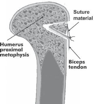
Schematic representation of suture sling technique. The biceps tendon was introduced in a tunnel placed in the proximal humerus. Nonabsorbable braided sutures were used to fix the tendon on itself.
Tenodesis Screw Group
A tunnel that was 9 mm wide and 30 mm long was drilled in the anterior-to-posterior direction at the anatomical neck level, perpendicular to the diaphyseal axis (Figure 2). The tendon was fixed in the tunnel using a bioabsorbable TS that was 9 mm wide and 23 mm long, according to the recommendations of the manufacturer. A Krackow-type suture was placed and tied at the proximal end of the tendon. One of the sutures was passed through the screw and the cannulated screwdriver, provided by the manufacturer. The tendon was pushed into the tunnel using the distal end of the screwdriver while the free end of the suture was tensioned by the surgeon. The 9-mm screw was driven into the tunnel without releasing the tensioned suture. After the screw was completely inserted, both ends of the suture were tied again over the screw.
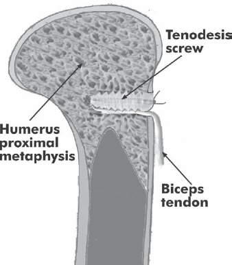
Schematic representation of fixation with tenodesis screw.
Anchor Group
The periosteum in the bicipital groove of the sheep in the anchor group was removed with a curette, and the tendon was fixed to this site with the help of two 3.5-mm corkscrew-type anchors, placed with a longitudinal distance of 10 mm (Figure 3). The suture material used was Ethibond No. 2.
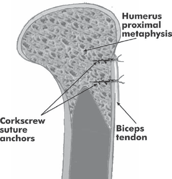
Schematic representation of fixation with double suture anchor.
After skin closure, all sheep were tagged for identification. They were fed a routine normal diet during the follow-up period. The sutures were removed on postoperative day 10. The animals were allowed to mobilize after they recovered from anesthesia. The sheep were limping for about 3 postoperative days and were walking normally after that period.
Specimen Preparation
The animals were sacrificed under sedation. Specimens consisting of the proximal humerus and biceps muscle were harvested on both sides. The fibrous granulation tissue around the tendon and muscle was removed until the biceps muscle belly could be moved freely. After radiographic documentation, the specimens were kept at room temperature for 4 hours or less, until the tensile tests were performed.
Failure Test Protocol
The failure tests were carried out on a materials testing machine (Universal Material Testing Machine, Model/Serial No. SM 100/J1007/4, Tecquipment Ltd, Nottingham, England). The calibration of the load and displacement transducers was performed in the laboratory environment before each test. Specimens were fixed into the device with the help of custom-made clamps (Figure 4A) so that the tendon was pulled with an angle of about 20° relative to the diaphysis (Figure 4B). This small amount of divergence prevented any contact between the humeral bone and the muscle belly during the tensile tests, and the direction of pull was still in close proximity to the original direction of the biceps muscle. The proximal humerus was fixed in the upper jaw using 2 parallel rods passing through the bone and the metallic jaw. For secure fixation of the biceps muscle belly in the lower jaw, the proximal biceps tendon was first augmented using transverse sutures with No. 5 Ethibond. After this, a cerclage wire 0.9 mm in diameter was passed over these augmentation sutures. The muscle belly was held in a soft tissue clamp, and cerclage wires were fixed around the clamps.
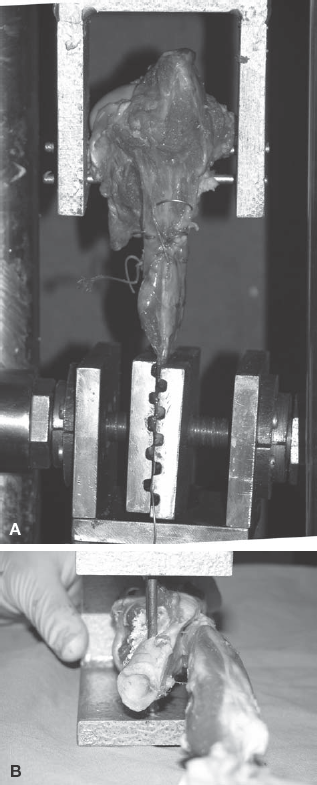
A, specimens were fixed to the jaws of the materials testing device using transfixing rods at the humeral site and soft tissue clamps for the biceps muscle belly. For secure fixation of the soft tissue, placement of a cerclage wire and nonabsorbable sutures was required at the muscle-tendon junction. B, the biceps tendon was pulled with an angle of 20° relative to the humeral shaft, simulating physiologic loading.
A pretension of 1 N was applied, and tension tests were performed at a rate of 10 mm/min, until the bone–fixation system–tendon complex failed by either tendon pullout or tendon rupture. The data obtained from the transducers were simultaneously recorded on a personal computer at 10 Hz using a data-acquisition system (ESAM Traveller Data Acquisition System, No. AA0EA01178, Vishay Measurements Group, Selb, Germany) for the quasi-static loading condition. The failure loads (in newtons) and the failure modes of the ligaments were recorded during the experiments along with the force-displacement variations in time. The peak value before the acute decline in the load-distraction curve was taken as the load to failure.
Histologic Examination
In the samples selected for histologic examination, all fixation material except for nonabsorbable suture material was extracted. After dissection, bone blocks of 3 × 3 cm including the tenodesis areas were cut out using a reciprocating saw. After a decalcification period, paraffin blocks of the samples were prepared, and thin sections were obtained parallel to the longitudinal axis of the tendon. Samples were stained with H&E as well as Masson trichrome to identify the collagenous and bony structures.
Statistical Analysis
A 1-way analysis of variance was used to make 2 different assessments: first, to compare different tenodesis types (including the intact tendon) after 0, 3, 6, and 9 weeks postoperatively and, second, to compare the results after 0, 3, 6, and 9 weeks of each separate tenodesis type. The Tukey honest significant difference post hoc test was used to identify which specific groups were significantly different. A P value less than. 05 was considered indicative of statistical significance. All statistical analyses were performed with SPSS for Windows standard version 10.0.1 software (SPSS Science Inc, Chicago, Ill).
Results
Two sheep were lost during the study period, one postoperatively because of pulmonary complications and the other perioperatively. These animals were replaced.
Failure Test Results
On the day of operation, the sutures were cut through the metaphysial bone in the SS group (mean load, 228 ± 29 N), the tendons were pulled out with a mean load of 164 ± 45 N in the TS group, and sutures were cut through the tendon in the anchor group (mean load, 203 ± 32 N) (Figure 5 and Table 1).
Biomechanical Test Results: Mean Failure Load for the 3 Fixation Methods a
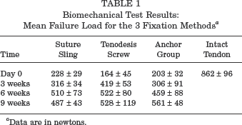
Data are in newtons.
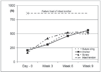
Graphic representation of results. The SDs of the results are given in Table 1.
The failure mode was again tendon pullout for all groups at the end of the third week, with a maximum pull-out strength of 316 ± 34 N, 419 ± 53 N, and 306 ± 91 N, respectively, for the SS, TS, and anchor groups. At the end of the sixth week, only tendon ruptures were observed. Maximum failure loads were measured as 510 ± 73 N, 522 ± 80 N, and 459 ± 88 N, respectively. At the end of the ninth week, tendon rupture was again the unique failure mode. Maximum failure loads were 487 ± 43 N in the SS group, 528 ± 119 N in the TS group, and 561 ± 48 N in the anchor group.
In the third week, only the TS group results were significantly higher than the corresponding day 0 results (mean difference, 255 N; 95% confidence interval [CI], 62–448 N; P =. 009). In week 6, all tenodesis types became significantly higher than their corresponding day 0 results (SS group: mean difference, 282 N; 95% CI, 166–398 N; P <. 001; TS group: mean difference, 358 N; 95% CI, 165–551 N; P <. 001; anchor group: mean difference, 257 N; 95% CI, 88–425 N; P =. 003).
No significant difference could be shown when the 3 tenodesis types were compared, neither on the day of operation nor at weeks 3, 6, and 9.
Tensile tests in cadaveric sheep shoulder samples revealed that intact biceps tendons were tearing off the glenoid rim with a mean load of 862 ± 96 N. This load was significantly higher than the mean values of all 3 groups for all tested time periods (mean difference, 301 N; 95% CI, 100–302 N; P <. 004, or higher significance).
Histologic Results
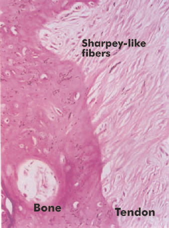
A fibrovascular interface was observed between the tendon and bone in all of the 3-week samples. Intermittent cartilage formation was also noted. At 6 weeks, the presence of a layer of fibrocartilaginous tissue in between tendon and bone was prominent in all 3 groups. Again in all 3 groups, reactive bone tissue formation and Sharpey-like fibers were also noticed (Figure 6). At 9 weeks, reactive bone tissue and cartilaginous islets were formed, aligning toward the bone in the TS group. No inflammatory infiltration was identified in the tendon, except for a few foreign-body giant cells present around the suture material. In the SS group, cartilaginous tissue was absent in the tendon-bone interface at the entrance of the tunnel (Figure 7). In areas other than the entrance, reactive bone formation could be demonstrated. The tendon within the tunnel showed increased cellularity. In the suture anchor group, reactive bone formation and Sharpey-like fibers were predominant in the bone-tendon interface (Figure 8).
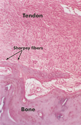
Tenodesis screw group, week 6. Sharpey-like fibers can be identified. H&E staining, original magnification ×32.
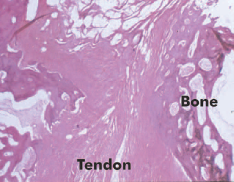
Suture sling group, week 9. Section at the inferior tunnel orifice. Formation of a direct-type insertion at the tunnel entry. H&E staining, original magnification ×16.
Anchor group, week 9. Indirect type of tendon insertion with Sharpey-like fibers. H&E staining, original magnification ×300.
Discussion
There are a large number of techniques used for tenodesis of tendons to the bone. Studies comparing various tendon fixation techniques used in cruciate ligament reconstructions showed time-dependent changes in biomechanical and histologic properties of tenodeses.18,20,26,27 A recent study comparing initial fixation strengths of 3 biceps tenodesis techniques also reported significant differences. 10 The current study is the first to compare the time-dependent changes in failure loads of biceps tenodesis techniques.
The tested methods represent 3 major types of biceps tenodesis techniques; the 2 intraosseous (bone tunnel) techniques have different fixation characteristics. The TS is an intratunnel fixation device and provides compression between the tendon and bone for the entire length of the tunnel. The SS technique is an extratunnel fixation and has no or only minor compression. The third method represents the extraosseous (bone surface) fixation techniques, which are gaining popularity because of their simplicity and possibility for arthroscopically assisted fixation. Screw-type anchors without predrilling were preferred in the present study because they have been reported to have the highest pull-out strength. 5 Anchor pullout was never the failure mode, and suture cutout through the tendon was the main failure mode in the anchor group for the first 3 weeks.
The keyhole technique of Froimson and Oh, 7 which is one of the most commonly preferred techniques, was not tested in this study because of the limited length and different shape of the biceps tendon of the sheep. It is shorter, flatter, and wider than the human counterpart. Knotting of such a tendon results in a larger knot and a too-short tendon for grasping. Depending on these technical difficulties, Jayamoorthy et al preferred tenodesis of the extensor digitorum longus tendon on the humerus in their in vitro model. 10 We preferred to replace the technique of Froimson and Oh with another intraosseous model.
All 3 techniques appeared to have similar failure loads on the day of surgery and until postoperative week 9 (Figure 5). On the day of implantation, the TS technique (mean failure load, 164 ± 45 N) composed the weakest group, with no statistically significant difference. Previous biomechanical studies have revealed similar results. In a comparison of 6 ligament fixation techniques, the fixation strength provided by the bioabsorbable interference screw (BIS) was the weakest, second only to the staple technique, whereas 3 different washer types and the suture post technique were found to be more stable than were the bioabsorbable screws. 24 Another bone tunnel study conducted on sheep extensor digitorum longus tendons reported bioabsorbable screws to be less stable than was the WasherLoc system. 20 The keyhole technique was also more stable than was screw fixation. 10
Extratunnel fixation techniques similar to our SS technique are the most commonly preferred group in experimental studies investigating the biomechanical properties of tendon-bone healing.8,18 Nevertheless, these studies did not report the day 0 fixation strength of the technique.
The anchor technique has not been previously investigated in experimental studies; thus, our results cannot be compared with other studies. Contrarily, the Bio-Tenodesis Screw is a member of the BIS family and has been the subject of many studies. A comparison of the failure loads of TS group day 0 results with the values given in previously reported studies proved that our results were lower than most of the reported values, in which the BIS provided a fixation strength ranging between 267 and 776 N in various tendons of various species in various experimental settings.11,14,19,27–29 On the other hand, a fixation strength as low as 183 N was reported by Walton. 24 These inconsistencies in fixation strengths of the BIS are related to the tunnel, screw, and tendon diameter ratios; bone quality; insertion torque 4 ; screw length 19 ; tendon length; and fit, 8 as well as to the mechanical properties of the investigated tendons. 14 Thus, we believe that a direct comparison of absolute values of failure loads obtained in different laboratory settings would be misleading.
In contrast to the day 0 results, the TS group was relatively stronger than were the remaining 2 groups in the third week (P =. 057). The TS group was also significantly stronger in the third week compared to the day 0 values (P =. 009). The remaining 2 groups reached significantly higher values in the sixth week (Figure 5). Considering the fact that the TS group was the weakest group on the day of operation, this increase in mean failure load within the first 3 weeks is noteworthy. The failure mode of the tendon– fixation device–bone complex remained unchanged in the third week for all 3 groups and was tendon pullout from the fixation site. Therefore, this increase in the failure load can be explained either by an increased healing process at the fixation site or by an increase of the fixation strength of the fixation device.
Differences in the healing characteristics of various tenodesis techniques have been reported in previous histologic studies. In bone tunnel techniques using extratunnel non-compressing fixation methods (SS group in the present study), tendon-to-bone healing occurs via an indirect insertion, with the development of a broad fibrocartilage layer resulting in the formation of Sharpey fibers.12,17,20,23,29 Recent experimental studies by Weiler et al on intratunnel compressive fixation using the BIS found that compression fixation had different healing characteristics.26,29 The fibrocartilage between the graft tissue and bone tunnel was only partially developed. The authors assumed that the healing had progressed partially by direct-contact healing. This finding was more prominent at the tunnel entrance. According to these findings, Weiler et al concluded that intratunnel interference fit fixation was superior to extratunnel fixation methods.
Although our biomechanical findings were in accordance with the conclusions of Weiler et al, our histologic findings did not support their hypothesis. In contrast to their report, the direct-contact healing at the tunnel entrance was observed in the extratunnel fixation group in our study, indicating that this difference could be an incidental finding. No major differences were seen between the histologic findings of both intraosseous and extraosseous fixation sites and methods.
In an extra-articular animal model comparing the effects of the BIS and WasherLoc system (an extratunnel fixation method), Singhatat et al found that the strength and stiffness of the healing tendon-bone interface might differ depending on the type of fixation. 20 On the fourth postoperative week, the extratunnel system had better results than did the BIS technique, contradictory to our findings. The authors explained this difference to be a result of decreased tendon-bone contact area within the bone tunnel and possible negative interference of the BIS with the formation of the biologic bond. The BIS might have prevented the ingrowth of blood vessels along the entire length of the tendon graft, compressing the tendon within the tunnel. The authors recommended fixation devices that grip the tendon graft either at the end of or outside the bone tunnel. The results of Singhatat et al are not consistent with our findings, and we could not find an explanation for this difference.
The healing properties of extraosseous fixation may be expected to be different from those of bone tunnel techniques because the tendon is apposed to cortical bone instead of metaphysial bone. This hypothesis was previously investigated by a limited number of experimental studies. The study by St Pierre et al 22 found no difference between the biomechanical and histologic properties of tendons attached into a cancellous trough or to cortical bone. In contrast to this finding, a recent experimental study has reported that reattachment of tendons to cortical bone might be better than those fixed to cancellous bone. 21 The design of our study together with the limited number of histologic specimens did not allow us to make any conclusion about the effect of fixation site on the biomechanical properties of the tenodesis. In addition, observed differences between histologic healing properties of intraosseous and extraosseous fixation sites were not prominent.
Another possible explanation of the acute increase in the screw fixation strength might be related to the in vivo changes in the physical properties of the biodegradable screw itself. Recently, an increase in the fixation strength of PLLA interference screws after intra-articular tenodesis was reported in an experimental study. 11 This increase was not accompanied by an increase in the screw diameter. The authors explained these findings with the observations of Mainil-Varlet et al, who found an acute water uptake by an increase in the crystallinity of the PLLA rods, without an increase in rod diameter. 15 Although results of these preliminary studies have not yet been verified, they provide a strong alternative for the explanation of the acute increase in our BIS group.
The clinical relevance of this experimental study is strongly correlated with the obtained failure-load curves. These curves had 2 main features (Figure 5): (1) all 3 curves remained above their day 0 results for the study period, and (2) a constant increase in failure loads was observed in all groups for the first 6 weeks.
Most of the experimental studies investigating the time-dependent changes in the failure load of various tendon–fixation site–bone units have used bone tunnels with an intra-articular opening. These studies were performed without removing the fixation material during failure tests. They uniformly have reported an acute decrease between day 0 and week 6 and a steady increase after postoperative week 6.3,11,14,25,28 Because the failure mode was changed to intrasubstance tendon rupture at week 2 or 3, these studies were unable to measure the biomechanical changes at the fixation site. Despite the high number of intra-articular studies, only a few studies including the current study have investigated the extra-articular tenodesis techniques without removing the fixation material. The study by Singhatat et al used an intraosseous model and reported an increase within the first 4 weeks. 20 An extra-articular and extraosseous patellar tendon model was used by Harrison et al, which aimed to evaluate a new suture anchor. 9 They reported a constant increase in the failure load of the tenodesis, similar to the results of Singhatat et al 20 and the results of the current study.
The 2 intraosseous and 1 extraosseous tenodeses in this study showed a constant increase in failure loads, indicating that the tendon–fixation site–bone unit never became weaker than the initial fixation strength achieved during the surgical procedure. In contrast to the failure-load curves, the numerical results obtained in the study cannot easily be projected to clinical practice. In a previous experiment by Magen et al, failure loads of interference screw fixation of double-looped tendon grafts were 2 times higher for bovine tendons compared to young human tendons. 14 The authors concluded that the animal tissue should not be used to estimate the performance of the interference screw in human tissue. In addition to this, the strength of fixation necessary to resume the activities of daily living is unknown, and thus we cannot comment about the sufficiency of the failure loads obtained in this animal study. It also should be noted that the failure loads of all groups remained significantly weaker than the failure load of the intact tendon. Despite the presence of promising findings, we cannot simply recommend making changes to currently preferred immobilization and rehabilitation protocols after biceps tenodesis.
A limitation that needs to be mentioned is that cyclic loading was not included in the study protocol. The authors believe that this is not a major limitation of the present study, which was not designed to find out if the tenodeses can survive a given cyclic load (eg, loads of daily activities) at different time intervals. Even if the cyclic loading tests were added to the study protocol, the presented study should be performed initially to detect the maximum value of the cyclic load, which should be applied to all tenodeses at all time intervals.
Conclusion
According to the results of this animal study comparing the healing properties of 3 different biceps tenodesis methods, the following conclusions may be drawn:
All 3 tested techniques provided similar fixation strengths on the day of implantation and at 3, 6, and 9 weeks postoperatively. All 3 techniques demonstrated increased failure loads at 6 and 9 weeks postoperatively.
The failure load of biceps tenodesis did not weaken after surgery but increased for all 3 techniques.
The increase in failure load of screw tenodesis compared to time zero was statistically significant at 3 weeks, whereas it was not significant until 6 weeks postoperatively with the other 2 techniques. The reason for this difference needs to be clarified.