
Abstract
Endoscopic ACL reconstruction is one of the most successful and commonly performed orthopaedic operations, yet there is considerable variability in the techniques employed. A growing body of literature is confirming that anatomic placement of tibial and femoral attachments results in improved knee stability and biomechanical performance of the graft. 13,19,22
Some authors have questioned whether the most common technique—a transtibial, single-bundle reconstruction— can effectively recreate both femoral and tibial ACL insertions. 1,9,22 The most limiting factor in restoring insertional anatomy with a transtibial technique has been the dependence of femoral tunnel position on the tibial tunnel. In theory, perfect transtibial access to the femur should be provided by a tibial tunnel that is colinear with a line connecting the centers of both femoral and tibial insertions. Heming et al 9 used a cadaveric model to demonstrate that this trajectory may not be practical, noting that a guide pin drilled antegrade through the center of both femoral and tibial ACL insertions will consistently exit the tibia within millimeters of the joint line. The implication of this and other investigations 1,22 is that traditionally more distal tibial starting points (3-4 cm distal to the joint line) are nonlinear and will result in less than anatomic graft positioning on the femur.
Despite these concerns, no reports have fully evaluated the potential of a transtibial single-bundle technique because none have simultaneously controlled for both tibial and femoral insertional anatomy, tibial tunnel starting point, and the increased flexibility that a reamed tibial tunnel may provide when placing instruments through it.
The purpose of this study was to clarify the true potential of a transtibial technique by focusing on the importance of tibial tunnel starting position. We began with the premise that the ideal transtibial trajectory is defined by a line connecting the center of the femoral and tibial insertions, recognizing that this exact trajectory is likely impractical for the very proximal tibial starting point that would be required. 9 Given the potential problems of tunnel integrity and graft-tunnel mismatch provided by such a proximal starting point, we identified more distal tibial tunnel starting positions that mitigated these variables to determine if the flexibility afforded by the reaming of a 11-mm tibial tunnel would allow appropriate femoral tunnel position. Using these starting points, we prepared tibial and femoral tunnels using a transtibial technique, and the ultimate intra-articular tunnel positions were compared with those of the native insertions. Our hypothesis was that anatomic placement of tibial and femoral tunnels for transtibial ACL reconstruction could be achieved with tibial tunnel starting points that were more proximal than traditional starting positions yet still practical.
Methods
Eight fresh-frozen adult knee specimens (mid-femur to mid-tibia, 4 right, 4 left) without ligamentous injury or significant degenerative joint disease were thawed over 24 hours. Before any dissection, computer-assisted navigation sensors (BrainLAB, Munich, Germany) were fixed with threaded pins to the femur and tibia. Sensor position was registered using navigation software and C-arm fluoroscopy, each femur and tibia was then mounted using a custom mount at 90° of flexion. This flexion angle was chosen as it is the most common position of the knee during transtibial reconstruction techniques. Given concerns that the necessary exposure of the ACL insertions could destabilize the knee and cause abnormal motion of the femur and tibia relative to each other during the study, a 3-point coordinate system was arbitrarily defined on each specimen by choosing and marking a point on the femur, tibia, and laboratory table, the x, y, z coordinates of each point were measured and recorded with a digitizer (MicroScribe; CNC Services, Amherst, Virginia), accurate to 0.05 mm. Both the digitizer and the mount were securely fixed to the same laboratory table, and for each knee, the 3-point coordinate system was repeatedly referenced with the digitizer throughout the study to confirm no subsequent motion of the femur, tibia, and digitizer relative to each other.
After each specimen was secured as described, the lateral femoral condyle was further secured to the lateral tibial plateau with 2 divergent K-wires and the extra-articular soft tissues then removed. Before removal of the extensor mechanism, the central third patellar tendon length was measured and the intact nature of both the articular cartilage and cruciate ligaments was confirmed.
To allow later 3-dimensional analysis, the surface anatomy of the femur and tibia was then assessed using the digitizer to record extensive point cloud arrays of both bones. The medial femoral condyle was then carefully removed with an oscillating saw—avoiding any disturbance of the femoral insertion site—and the ACL was sharply removed with care to identify the centers and margins of both the femoral and tibial insertions, first by marking them with a pen and then using the digitizer.
BrainLAB computer-assisted navigation was then used to identify the tibial exit point of a line connecting the centers of the tibial and femoral ACL insertions (the “anatomic exit point”) as well as points distal to this on the tibia that corresponded with 10 mm and 0 mm of graft-tunnel mismatch. Mismatch was calculated using the tibial tunnel length (TT) for the given starting point (measured with the digitizer from the external tibia to the center of the tibial footprint), the measured intra-articular distance (IAD) between the insertional centers, and the central third patellar tendon length for that specimen (N), where Mismatch = (N + 25 mm standard bone-tendon-bone [BTB] bone plug length) – (TT + IAD). Because the tibial tunnel length (TT) decreases as the tunnel starting point moves proximally on the tibia, and because 10 mm of mismatch was what we considered to be a reasonable upper limit of manageable, the 10-mm mismatch starting position (point A) represented the most proximal and still practical tibial tunnel starting point. In our opinion, 10 mm of mismatch can be managed by a combination of femoral tunnel recession and shortening of the tibial plug. Mismatch beyond 10 mm would require alteration of standard surgical technique or fixation. The zero mismatch starting point (point B) was further distal on the tibia, more closely resembling a traditional starting position. 15 For each point A and B, an effort was also made to optimize the coronal plane alignment with the native ACL, using the BrainLAB navigation to further guide medial to lateral position of each point on the proximal tibia (Figure 1).
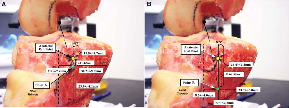
Tibial tunnel starting points. A, Point A (lower dot): This starting point was aligned as closely as possible with the native ACL in the coronal plane but was positioned distal enough on the tibia to prevent greater than 10 mm of bone-tendon-bone (BTB) autograft mismatch. Upper dot, anatomic exit point; TT, medial edge of the tibial tubercle; MTP, medial tibial plateau edge; Pes, top of the pes tendons; MCL, anterior edge of the medial collateral ligament. B, Point B (lower dot): Aligned as closely as possible with the native ligament in the coronal plane but distal enough on the tibia to ensure a tibial tunnel length with zero millimeters of BTB autograft mismatch (ie, tibial bone plug would be flush with outer tibial cortex), this point corresponded with a more traditional starting point. Upper dot, anatomic exit point; TT, medial edge of the tibial tubercle; MTP, medial tibial plateau edge; Pes, top of the pes tendons; MCL, anterior edge of the medial collateral ligament.
Guide pins were then drilled using a standard ACL tibial aimer (Smith & Nephew Endoscopy, Andover, Massachusetts) to the center of the marked tibial insertion, from point A in half of the knees and from point B in the other half (Figure 2). Guide pin intersection with the intercondylar notch wall was noted and recorded. Tibial tunnels were then reamed with an 11-mm cannulated reamer.
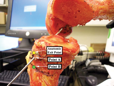
Guide pins were drilled from point A to the center of the tibial insertion in half of the knees and from point B in the other half. An 11-mm reamer was then used to drill tibial tunnels over the wires. Note anatomic exit point and point B—the wire is passing through point A.
After the tibial tunnel had been completed, a 7-mm offset aimer was inserted through the tibial tunnel and hooked around the posterior aspect of the intercondylar notch. An effort was made to take advantage of the maneuverability of the 11-mm tibial tunnel diameter by positioning the aimer in the posterolateral corner of the tibial tunnel and externally rotating the handle to achieve the lowest possible pin position on the lateral wall of the femoral notch. Once the aimer was positioned optimally, a guide pin was inserted through the aimer and the site of pin contact with the intercondylar notch marked and measured with respect to its distance from the center of the native ACL femoral insertion and surrounding notch landmarks.
The wire was then provisionally drilled into the femur in the above location and a 10-mm reamer passed over the wire and through the tibial tunnel only (ie, the femur was not yet contacted). The reamer was allowed to remove bone only from the posterior rim of the tunnel’s entrance into the joint. Because the guide pin had been placed posterolateral to the center of the tibial tunnel’s entrance into the joint, passing the reamer over the wire in this position consistently removed several millimeters of bone from the posterolateral aspect of the tibial tunnel rim, in a trajectory defined by the guide wire’s position. After this step was completed, the guide wire was removed and the new periphery of the tibial tunnel’s entrance into the joint was registered with the digitizer to quantify the amount of bone removed. The offset aimer was then reinserted through the now modified tibial tunnel and repositioned in the over-the-top position of the intercondylar notch. Once again, the aimer was externally rotated to allow the most favorable pin position relative to the marked center of the femoral insertion. A guide pin was once again inserted through the aimer and the position of the new contact point with the intercondylar notch measured. The pin was then drilled several centimeters into the femur (to allow its localization after completion of the notchplasty [see below]) and then removed with the aimer.
A notchplasty of the lateral intercondylar notch wall was then performed using a motorized bur, effecting a level resection of 3 mm. After the notchplasty had been completed, the distal femoral surface anatomy was once again registered with extensive point cloud arrays using the digitizer to allow post hoc 3-dimensional analysis (see below). The offset aimer and guide pin were then reinserted once again through the tibial tunnel, hooked around the back wall, and externally rotated. This final contact point was once again assessed, its distance to the pin tract from the prior guide wire noted.
Last, femoral tunnels were reamed with a 10-mm cannulated reamer and any cortical breakthrough of the back wall recorded. The digitizer was then used to register the edges of the femoral tunnel on the notch wall and to measure the distances of its margins from intercondylar notch landmarks.
After completion of the above, a number of subsequent analyses were performed using the spatial information recorded with the digitizer. Using the point cloud arrays, Matlab software (Mathworks, Inc, Natick, Massachusetts) was used to construct lines connecting each of points A and B with the center of the tibial insertion and to determine the resulting intersection point of each line with the lateral intercondylar notch. This analysis was meant to simulate a guide pin drilled through the tibia and allowed us to compare pin trajectory between the 2 different tibial starting points without having to actually drill pins from both locations in each specimen. The distance of these virtual pin intersections with the femur was then calculated from the center of the femoral insertion. Similar analysis was used to assess the amount of bone resected from the posterior aspect of the lateral intercondylar notch during each simulated notchplasty, using the pre- and postnotchplasty femoral point cloud arrays.
In addition, the surface areas of each tibial and femoral insertion were measured using the insertional periphery data recorded with the digitizer. Similar surface areas were calculated for the digitized peripheries of the intra-articular tibial tunnel exit and femoral tunnel. The percentage overlap of the tibial tunnel surface area with that of the native tibial insertion was then directly calculated. On the femoral side, insertional overlap was calculated to account for the notchplasty, which had been performed before reaming the femoral tunnel. The 3-Matic software (Materialise BV, Leuven, Belgium) was used to extrude a 3-dimensional shape defined by the femoral tunnel contour toward the prenotchplasty femoral point cloud, along an axis defined by the final guide wire position. Overlap of this “extruded femoral tunnel” with the native femoral insertion was then calculated on the prenotchplasty femoral point cloud.
Last, given some concerns over the practicality of beveling the posterior aspect of the tibial tunnel, additional analysis was performed to estimate the surface area and overlap of a femoral tunnel drilled prior to beveling of the tibial tunnel. The 3-Matic software was used to create a virtual 10-mm cylinder centered on the axis of the guide pin positioned just before tibial tunnel beveling, the intersection of this cylinder with the prenotchplasty femur was then quantified based on surface area and overlap with the native femoral insertion.
Comparison of continuous variables was performed with t tests, alpha set at 0.05, and P values below this considered significant. P values were not corrected for multiple comparisons and should be treated as such. Minimum sample size for comparison of point A vs B was determined by a power analysis (G*Power 3.0, Dusseldorf, Germany) with respect to transtibial pin position on the femoral notch. This analysis demonstrated a minimum sample size of 4 specimens per group for determining an effect size of 2.46 mm with a power of 82.6%.
Results
All specimens had intact cruciate ligaments and menisci, and none had significant degenerative joint disease. In all cases, the 3-point coordinate system used to reference the tibia, femur, and digitizer remained within 0.1 mm throughout the testing protocol. Measured anatomic indices were comparable with the published literature § and did not differ significantly when comparing specimens in which point A tibial tunnels were drilled vs specimens in which point B tunnels were used (P > .05). Insertional anatomy and other recorded anatomic variables are summarized in Appendix A (available in the online version of this article at http://ajs.sagepub.com/supplemental/).
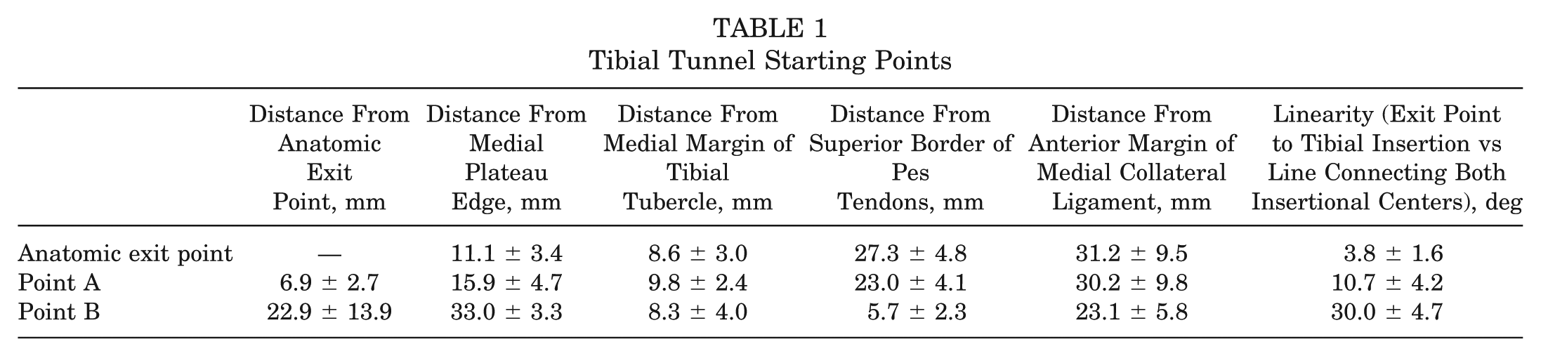
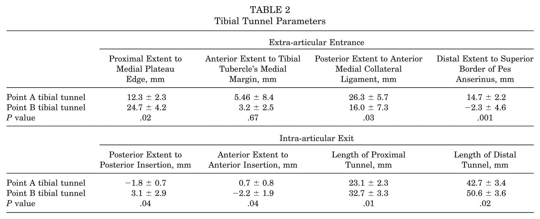
Point A occurred a mean 15.9 ± 4.5 mm below the medial plateau edge and 9.8 ± 2.4 mm posterior to the medial margin of the tibial tubercle, whereas point B occurred 33.0 ± 3.3 mm below the medial plateau edge and 8.3 ± 4.0 mm posterior to the medial margin of the tibial tubercle (Figures 1 and 2). Tunnels drilled from the more proximal point A maintained a shorter proximal bone bridge from the medial plateau edge (12.3 ± 2.3 mm vs 24.7 ± 4.2 mm) and a shorter proximal tunnel length (23.1 ± 2.3 mm vs 32.7 ± 3.3 mm) (Figure 3). The intra-articular entrance of the point A tibial tunnels very closely reproduced the native tibial footprint, whereas the point B tibial tunnels were more circular with less overlap (97.9% ± 1.4% vs 71.1% ± 15.1% for point B tunnels, P = .03). In no specimen did the tibial tunnel compromise the proximal bone bridge or the medial tibial plateau. Tibial starting points and tunnel dimensions are depicted in Tables 1 and 2.
Tibial Tunnel Starting Points
Tibial Tunnel Parameters
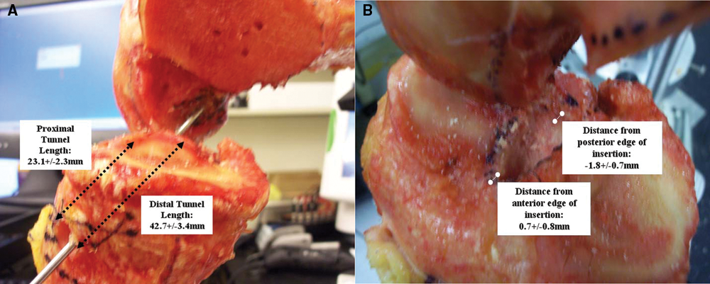
Tibial tunnels. An 11-mm reamer was passed over the guide wire in each knee, creating a tibial tunnel from either point A (shown with tunnel dimensions noted) or point B (not shown).
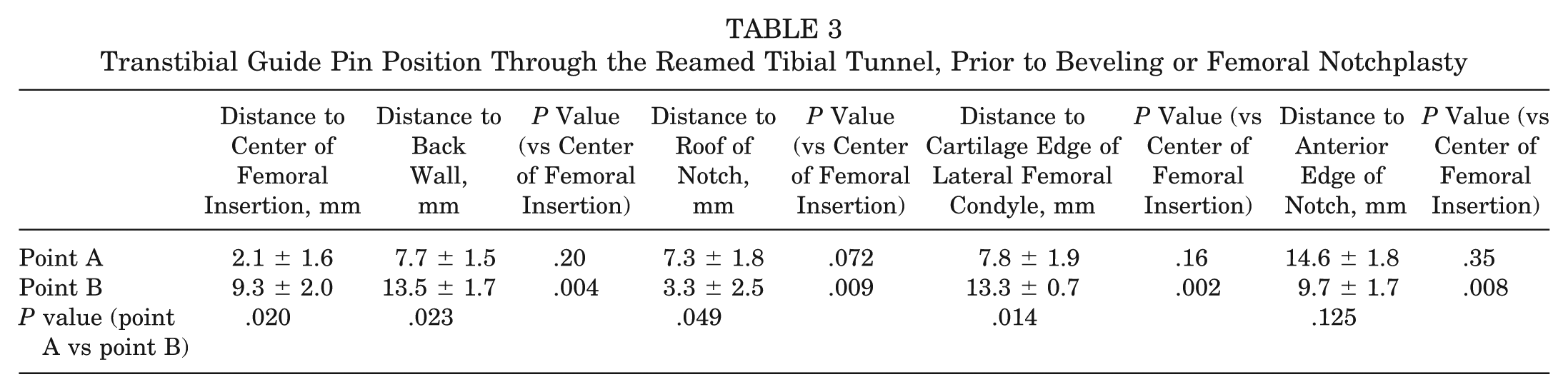
Transtibial femoral access is depicted in Appendix B (available online). Initial guide pin intersection with the intercondylar notch (using both actual guide pin data and virtual guide pin analysis) was significantly closer to the center of the femoral insertion when tibial tunnel starting point A was used as compared to point B (6.3 ± 2.5 mm vs 12.7 ± 2.6 mm; P = .0007). After reaming the tibial tunnel, transtibial guide pin position improved in all specimens but remained significantly closer to the center of the femoral insertion using the point A tibial tunnels (2.1 ± 1.6 mm from the center of the femoral insertion vs 9.3 ± 2.0 mm for the point B tibial tunnels; P = .02), a position that was not significantly different from that of the center of the femoral insertion with respect to distance from the roof, anterior, posterior, and inferior edges of the notch (Table 3).
Transtibial Guide Pin Position Through the Reamed Tibial Tunnel, Prior to Beveling or Femoral Notchplasty
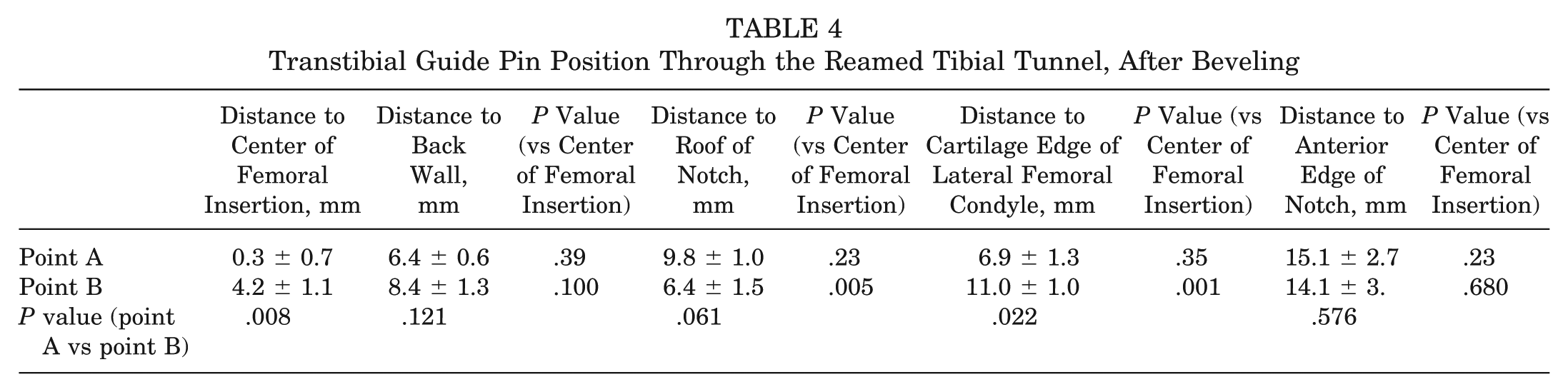
Beveling the posterolateral rim of the tibial tunnel’s entrance into the joint with the cannulated reamer resulted in 2.6 ± 1.3 mm and 7.0 ± 2.5 mm of bone removal from the posterolateral aspect of the point A and B tibial tunnels, respectively. Compared with the native insertion’s distance from the anterior edge of the PCL, this represented a significant posteriorization (P = .04) for both tunnels. After beveling had been completed and the offset aimer repositioned, the guide pin moved closer to the center of the femoral insertion in all knees but was significantly closer to the center of the insertion using the point A tibial tunnels (0.3 ± 0.7 mm vs 4.2 ± 1.1 mm for the point B tunnels; P = .008), a position that represented perfect centering of the guide pin in 3 of the 4 specimens (Table 4). By contrast, this best-case pin position for the point B tibial tunnels remained significantly higher than the center of the native femoral insertion (Table 4).
Transtibial Guide Pin Position Through the Reamed Tibial Tunnel, After Beveling
Volumetric analysis of femoral point clouds before and after notchplasty demonstrated a mean 3.2 ± 1.1 mm of bone removal from the posterolateral notch. After the notchplasty had been completed and the offset aimer repositioned, in all specimens, the guide pin trajectory followed precisely the same tract it had created immediately after the beveling stage, indicating that the notchplasty did not alter transtibial pin positioning.
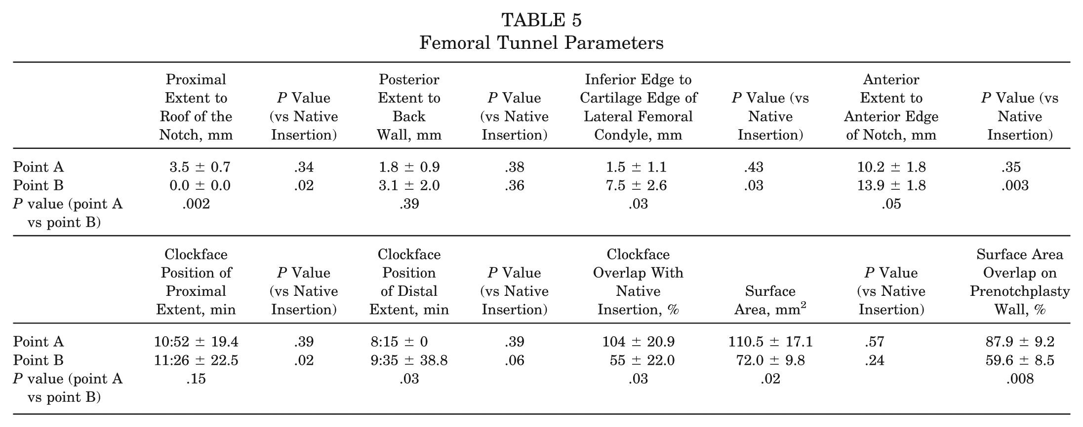
Femoral tunnels are shown in Figure 4, with parameters summarized in Table 5. In no specimen did any significant posterior wall breakthrough occur. Compared with the point B femoral tunnels, point A femoral tunnels had a significantly larger surface area with a lower position on the notch wall and an oblique anterior extent that trended toward being closer to the anterior edge of the notch. Compared with the native insertion, the margins of the point A femoral tunnels were not significantly different, whereas those of the point B femoral tunnels were notably more proximal and posterior. Surface area overlap with the native attachment was also higher for the point A femoral tunnels (87.9% ± 9.2% vs 59.6% ± 8.5%; P = .008). Combined tibial and femoral insertional overlap is summarized in Appendix C (figures and supplemental video available online).
Femoral Tunnel Parameters
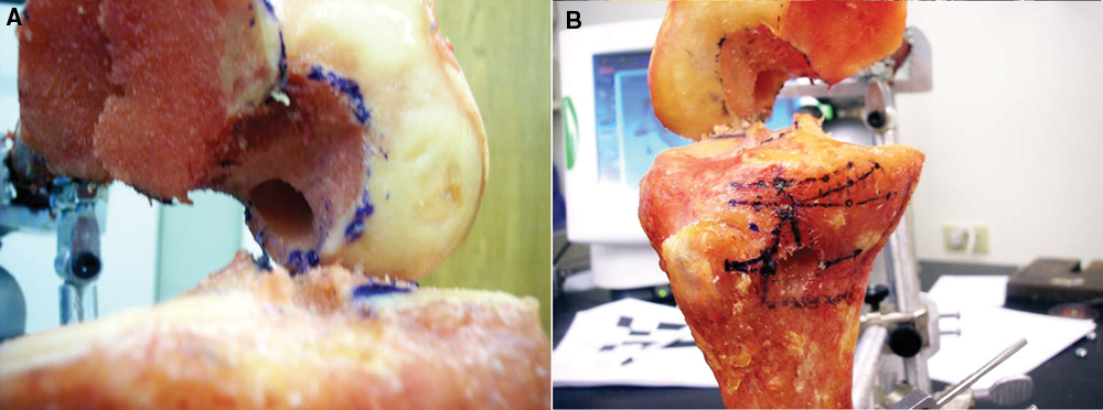
Femoral tunnels. A, Starting point A. The tibial tunnel orientation from starting point A allowed positioning of a guide pin at the center of the femoral insertion. The resulting femoral tunnel appeared to nearly perfectly overlap the native insertion. B, Starting point B. The tibial tunnel orientation from point B allowed a best-case scenario guide wire position that was above the center of the femoral insertion. The resulting femoral tunnel is positioned higher in the notch with a portion of the tunnel on the roof.
During post hoc analysis, when a 10-mm cylinder was added to the guide pin’s position before performing the notchplasty and beveling the tibial tunnel, intersection with the femoral notch produced femoral insertional overlap for the point A femoral tunnels that was roughly equivalent to that seen after the beveling step, yet overlap decreased substantially for the point B femoral tunnels (81.1% ± 12.5% overlap for point A vs 11.4% ± 13.0% overlap for point B; P = .003).
Discussion
The primary finding of this study is that anatomic transtibial positioning of both femoral and tibial tunnels is possible when a proximal starting point on the anteromedial tibial cortex is used. We believe these results are timely, given that the most commonly performed transtibial, single-bundle ACL reconstruction has come under recent criticism as several authors have questioned the ability of this method to anatomically position the femoral tunnel through the tibia. 1,9,22 In the recent cadaveric study by Heming et al, 9 the ideal transtibial trajectory required a tibial starting point 14.1 mm from the medial plateau edge, implying that more distal starting positions might be incapable of providing anatomic femoral access. Other authors have questioned whether it is even possible to connect the centers of both insertions with a single guide pin. 1 In part because of these limitations, transtibial alternatives have garnered attention, including drilling the femoral tunnel through the anteromedial portal 7,22 or even abandoning a single-bundle reconstruction altogether for double-bundle techniques. 24
Despite this widespread criticism, the true potential of a single-bundle, transtibial technique has not yet been fully evaluated because prior studies have not objectively controlled for the tibial tunnel starting point, both tibial and femoral insertional anatomy, or the potential maneuverability that a reamed tibial tunnel may provide linear instrumentation in accessing the femoral insertion. Working with the assumption that the most anatomic transtibial reconstruction should be made possible by a tibial tunnel that closely mirrors a line connecting the center of the femoral and tibial insertions, we reasoned that a tibial tunnel starting point that is as close as possible to the anatomic exit point—while also mitigating the graft-tunnel mismatch and tibial tunnel integrity challenges of a proximal starting position—would allow the best that a transtibial technique could practically accomplish. Our study differs from that of Heming et al 9 in that our tunnels were drilled retrograde in a manner similar to the technique used during surgery, and we were able to account for the increased flexibility associated with working through a reamed tibial tunnel. We also explored the potential value of more practical tibial starting positions than the single “ideal trajectory” of the study by Heming et al.
We found an optimum starting point (point A) to occur roughly 16 mm distal to the medial tibial plateau edge and 9 mm posteromedial to the medial margin of the tibial tubercle. Use of this tibial tunnel starting position resulted in tibial tunnels that we believe are practical but leave little margin for error and a relatively short tibial tunnel (average 23.1 mm). Our point A tibial tunnels maintained an average 12.3 mm of bone between the upper border of the tunnel and the edge of the plateau, with no fracture or compromise in any specimen. In addition, with a coronal plane orientation closer to the midline than traditional tunnels, the posteromedial margin of the tunnel maintained a midline position that never threatened the tibial articular surface as the tunnel entered the joint. Last, we believe the inherent 10 mm of mismatch in these tunnels is manageable. After recessing the femoral plug 5 to 10mm, these tunnels—whose 23.1 mm proximal length could accommodate most standard interference screws—would provide a worst-case scenario of 15 mm of plug/tunnel overlap on the tibial side, more than adequate for interference screw fixation of a bone plug. 3 Nonetheless, from a practical standpoint, use of this starting position would require close attention to detail—particularly with respect to the degree of medialization of the starting position—as the tunnel’s proximity to the medial plateau leaves much less margin for error than a more distal starting position. Furthermore, potential clinical concerns related to hardware placement, plateau fracture, or potential compromise of subchondral bone do exist and require further study before this technique could be recommended.
We also found that tibial tunnels created from point A allowed near-perfect access to the femoral insertion when compared with the more traditional point B, which was much less anatomic. These differences were apparent with initial guide pin intersection with the notch wall and became even more pronounced after the tibial tunnels had been prepared—the point A tibial tunnels allowing guide pin positioning within 2.1 mm of the insertion’s center (vs 9.3 mm for the point B tibial tunnels). These findings suggest that a reamed tibial tunnel provides substantial maneuverability for the tibial aimer and— when combined with a more proximal tibial starting point— allows near anatomic positioning on the femoral side. Beveling the posterolateral rim of the tibial tunnel allowed subsequent guide pin positioning directly on the insertional center for the point A tunnels (vs 4.2 mm above the center for the point B tunnels), whereas a femoral notchplasty did not improve access in any knee. Despite most surgeons’ comfort with viewing the ACL in the coronal plane, these findings underscore that tunnel obliquity in the sagittal plane—significantly more anatomic with a proximal tibial tunnel starting point—may be much more important in achieving a lower position on the notch wall.
We also found that use of the more proximal tibial tunnel starting position allowed more anatomic overlap with the native ACL footprints. Although the ovoid tibial insertion in each knee was reasonably overlapped by the point B tibial tunnel entrances into the joint (71.1% overlap), there was near-perfect reconstitution by the point A tibial tunnels (97.9% overlap). Overlap on the femoral side was also significantly greater using the more proximal tibial tunnel starting point, approaching 90% vs the point B femoral tunnels, which overlapped only the posterosuperior half of the native footprint. Even without beveling the tibial tunnel or performing a femoral notchplasty, our analysis found that use of point A would allow greater than 80% overlap of the native femoral insertion.
Taken together, these results demonstrate the following: (1) Transtibial femoral access is highly dependent on tibial tunnel orientation, the most important determinant of which is the external tibial starting point. (2) Tunnel orientation that more closely approximates the normal ligament’s anatomic axis achieves improved femoral positioning. (3) It is possible to simultaneously create a practical tibial tunnel that is centered on the native tibial insertion and—via a transtibial technique—position a guide wire at or very near the center of the native femoral insertion. (4) Bone tunnels created in this manner will closely reproduce the native tibial and femoral footprints. By contrast, our results also suggest that even with fairly significant tibial-sided modifications, a traditional tibial tunnel can at best get to a point 4 mm above the center of the femoral insertion with a resulting overlap of only 50% to 60%. The tendency of traditional, distal tibial tunnel starting positions to place the femoral tunnel higher than the native femoral insertion has also been reported by other authors. 22 Although further study is needed to evaluate the biomechanical implications of a graft positioned with the idealized point A, previous biomechanical studies have demonstrated that close reproduction of the normal ligament’s axis would bestow more normal kinematics than a vertically positioned graft and likely with minimal pathologic roof impingement. 11,22
Our study design is limited by its static evaluation of the ACL. Although we chose 90° of knee flexion as the most practical position to evaluate ACL reconstruction, the potential biomechanical implications of a normally dynamic ligament cannot be construed from a study design that evaluates the ligament in one knee position.
We also examined only 2 tibial tunnel starting positions, although we would argue these are likely to be fair representations of the best that a transtibial technique can accomplish. We are aware that some surgeons prefer to maintain a distal but very medial starting position (ie, close to the anterior edge of the MCL)—essentially maximizing coronal plane obliquity to get lower on the femoral notch. Although not directly evaluating these starting points, our results suggest tibial tunnels created from those locations are probably not allowing anatomic reconstructions. Without beveling substantial bone from the posterior aspect of our point B tibial tunnels, transtibial guide pin positioning was 13 mm from the back wall, implying that the sagittal plane obliquity of these distal starting points—which would only worsen with more posteromedial starting positions—would make it impossible for a 7-mm offset guide to reach the posterior wall without extending the knee, a maneuver that would likely risk posterior wall blowout. 9 We believe one of the notable findings of our study, which accounted for both tibial and femoral insertional anatomy, is the critical importance of sagittal plane obliquity in achieving lower notch positions. We believe obliquity in the sagittal plane is much more important than in the coronal plane and that tibial tunnels that lack this obliquity must compromise either on the tibial side (ie, with a more posteriorized entrance into the joint) or on the femoral side (ie, with nonanatomic positioning and/or posterior wall blowout). It is worth noting, however, that we have not evaluated the practical use of our findings in an operative setting. Reproducible identification of the appropriate tibial starting point may be difficult in a true clinical scenario without the use of navigation.
Another potential criticism of our study protocol is the degree to which the posterolateral aspect of the tibial tunnel’s intra-articular entrance was altered during the beveling stage. Beveling, which was performed at the tunnel rim only, had the effect of positioning the posterolateral aspects of both point A and B tibial tunnels an average of 3 to 4 mm posterior to the back of the native tibial insertion, which could be theorized to posteriorize the graft. The effect of beveling on the tibial tunnel aperture position does require further study. We believe it is important, however, that beveling was noted to occur at the tunnel rim only—not over a substantial span of the tunnel’s length. The portion of the tunnel involved in BTB fixation and the central axis of the graft would thus not be expected to change significantly, particularly for point A tibial tunnels where the resulting gap between the posterolateral rim and the graft would be only 2 to 3 mm. Likewise, the ultimate difference in femoral tunnel positioning using this modification is minimal (<2 mm difference in pin positioning and ~6% change in femoral insertional overlap), suggesting that, like the notchplasty, it is probably not an essential part of femoral positioning in properly oriented tibial tunnels anyway. Nonetheless, our study did not evaluate graft fixation or healing, and therefore we can only speculate as to the consequences of this particular tunnel modification.
Our study design also could be criticized for the degree of dissection required to expose the ACL’s insertions. As noted in the Methods section, soft tissues were removed en masse from each knee joint along with the medial femoral condyle to fully expose the insertions and could be theorized to have altered tibiofemoral orientation during the subsequent measurements. If present, we believe this effect was quite minimal. Each femur and tibia was registered against a static 3-point coordinate system after fixation at 90° and before any dissection. Subsequent measurements throughout the study protocol confirmed essentially no motion between femur, tibia, and digitizer. We would also point out that similar methods have been employed by other authors. 9
Last, it is noteworthy that our model examined tunnel diameters typically used for BTB grafts (ie, 10-11 mm), given their common use and potential technical limits (ie, graft-tunnel mismatch). Although our results suggest that a proximal tibial tunnel starting point would improve transtibial femoral access for any size tunnel, the potential implications of a narrower tunnel (ie, 7-9 mm for a soft tissue graft) are currently unknown and are the subject of ongoing investigation.
Conclusion
Despite recent criticisms, a transtibial single-bundle technique can provide a highly anatomic reconstruction of the ACL. The most important factor in determining femoral access with a transtibial technique appears to be the tibial starting point. Traditional tibial starting points may indeed limit access on the femoral side, resulting in less than 60% overlap of the native femoral insertion. However, when the tibial starting point is meticulously aligned with the native ligament’s axis and moved to a more proximal position, a transtibial single-bundle technique can center a graft along the central axis of both tibial and femoral insertions with roughly 90+% insertional overlap, a manageable amount of graft-tunnel mismatch, and maintenance of tunnel integrity.
Footnotes
References
Supplementary Material
Please find the following supplemental material available below.
For Open Access articles published under a Creative Commons License, all supplemental material carries the same license as the article it is associated with.
For non-Open Access articles published, all supplemental material carries a non-exclusive license, and permission requests for re-use of supplemental material or any part of supplemental material shall be sent directly to the copyright owner as specified in the copyright notice associated with the article.