
Abstract
Background:
Syndesmosis sprains can contribute to chronic pain and instability, which are often indications for surgical intervention. The literature lacks sufficient objective data detailing the complex anatomy and localized osseous landmarks essential for current surgical techniques.
Purpose:
To qualitatively and quantitatively analyze the anatomy of the 3 syndesmotic ligaments with respect to surgically identifiable bony landmarks.
Study Design:
Descriptive laboratory study.
Methods:
Sixteen ankle specimens were dissected to identify the anterior inferior tibiofibular ligament (AITFL), posterior inferior tibiofibular ligament (PITFL), interosseous tibiofibular ligament (ITFL), and bony anatomy. Ligament lengths, footprints, and orientations were measured in reference to bony landmarks by use of an anatomically based coordinate system and a 3-dimensional coordinate measuring device.
Results:
The syndesmotic ligaments were identified in all specimens. The pyramidal-shaped ITFL was the broadest, originating from the distal interosseous membrane expansion, extending distally, and terminating 9.3 mm (95% CI, 8.3-10.2 mm) proximal to the central plafond. The tibial cartilage extended 3.6 mm (95% CI, 2.8-4.4 mm) above the plafond, a subset of which articulated directly with the fibular cartilage located 5.2 mm (95% CI, 4.6-5.8 mm) posterior to the anterolateral corner of the tibial plafond. The primary AITFL band(s) originated from the tibia 9.3 mm (95% CI, 8.6-10.0 mm) superior and medial to the anterolateral corner of the tibial plafond and inserted on the fibula 30.5 mm (95% CI, 28.5-32.4 mm) proximal and anterior to the inferior tip of the lateral malleolus. Superficial fibers of the PITFL originated along the distolateral border of the posterolateral tubercle of the tibia 8.0 mm (95% CI, 7.5-8.4 mm) proximal and medial to the posterolateral corner of the plafond and inserted along the medial border of the peroneal groove 26.3 mm (95% CI, 24.5-28.1 mm) superior and posterior to the inferior tip of the lateral malleolus.
Conclusion:
The qualitative and quantitative anatomy of the syndesmotic ligaments was reproducibly described and defined with respect to surgically identifiable bony prominences.
Clinical Relevance:
Data regarding anatomic attachment sites and distances to bony prominences can optimize current surgical fixation techniques, improve anatomic restoration, and reduce the risk of iatrogenic injury from malreduction or misplaced implants. Quantitative data also provide the consistency required for the development of anatomic reconstructions.
Keywords
Syndesmotic injuries, colloquially referred to as high ankle sprains, account for up to 25% of ankle sprains in athletic populations. 24 Although reported to occur less frequently than lateral ankle sprains, syndesmotic sprains usually require longer periods of recovery resulting in greater time loss from sport.7,15,48 Syndesmosis sprains also have been reported to have a lower sensitivity of diagnosis with physical examination, stress radiography, computed tomography (CT) scans, and magnetic resonance imaging (MRI) scans. § Undiagnosed or incompletely diagnosed syndesmosis injuries can lead to ankle pain, worsen athletic performance, lengthen recovery, and ultimately cause arthrosis.15,22,26
Despite increasing attention in the literature, the diagnosis and treatment of acute and chronic syndesmosis injuries remain controversial.44,46 No single physical examination tool is clearly indicative, and the necessity for surgical treatment of the injury becomes immediately clear only when there is frank diastasis confirmed by radiographic means.9,14,17,24,44,51 Even CT and MRI, which have reported greater sensitivity, have their limitations.36,45 Furthermore, debate also exists regarding optimal repair techniques in both the chronic and acute settings, with suggestions ranging from arthroscopic treatment to open repair that may be accompanied by a variety of tibiofibular fixation methods including screws and cortical fixation devices.3,31,38,46 Given the current clinical environment, a clear need exists for additional basic science and diagnostic information.
Currently, a limited amount of information exists describing the anatomic characteristics of the syndesmosis, especially regarding the length, orientation, and footprint areas of the syndesmotic ligaments.1,13,19 Given the frequency of injury and increasing necessity for surgical intervention, a more comprehensive anatomic understanding of the ankle syndesmosis is warranted. Quantitative anatomic information characterizing the anterior inferior tibiofibular ligament (AITFL), the posterior inferior tibiofibular ligament (PITFL), including both the superficial and deep transverse constituents, and the interosseous tibiofibular ligament (ITFL) will help practitioners to more accurately diagnosis injuries and develop anatomic surgical fixation techniques. Furthermore, information regarding the articulation of the distal segments of the tibia and fibula, including the areas and locations of articular cartilage and synovial joint space, may be important to reduce the risk of iatrogenic cartilage injury and mitigate the risk of arthritis.
The purpose of this study was to qualitatively and quantitatively analyze and establish detailed information pertaining to the syndesmotic ligaments. It was hypothesized that the origins, insertions, footprint areas, ligament lengths, and spatial orientations with respect to relevant bony landmarks could be consistently defined for the 3 syndesmotic ligaments. The results of this study may help provide clinically pertinent quantitative data and improve the treatment of syndesmosis injuries.
Materials and Methods
Specimen Preparation
Sixteen nonpaired, fresh-frozen human cadaveric specimens, with a mean age of 59.6 years (range, 48-90 years; 5 female and 11 male) and no history of injury were used in this study. Dissections were performed to identify both the ligamentous structures of the ankle syndesmosis, including the AITFL, PITFL, and ITFL, and the relevant bony structures. Specimens were positioned in a neutral stance, which was defined by neutral flexion using a goniometer. Two screws were simultaneously inserted along the medial-lateral axis through the fibula into the tibia approximately 10 and 15 cm, respectively, proximal to the plafond. Specimens were then dissected of all tissue proximal to the screw fixation to allow the tibia and fibula to be secured in polymethylmethacrylate (PMMA; Fricke Dental International, Inc). The remaining overlying muscular, tendinous, and neurovascular structures were excised to expose the relevant syndesmotic structures for accurate identification. Ligaments and their respective borders were then defined by the dense, parallel orientation of collagen fibers. According to these criteria, the bands of the AITFL, including the accessory band or Bassett ligament, 2 and those of the PITFL, including the superficial and deep transverse tibiofibular constituents, were identified according to their distinct origins and insertions. In the case of multifascicular ligaments, individual bands were defined where distinct separations between bundles of fibers could be distinguished along the entirety of the interinsertional course after the removal of intercalating adipose tissue. Specimens were subsequently disarticulated proximal to the talus and loaded into a custom fixture with the distal end extending upward at an approximately 45° angle with the laboratory bench to ensure access to all relevant structures.
Anatomic Measurements
Three-dimensional (3D) positional data of the syndesmotic ligament attachments, footprints, and relevant osseous landmarks of the tibia and fibula were collected by use of a coordinate measuring device (MicroScribe-MX; GoMeasure3D) with a needle point tip and a recorded point repeatability of 0.113 mm as previously described. 25 Before data collection, the anatomic relationship of the tibia and fibula was defined by use of coordinate frames attached to both the tibia and the fibula. This relationship was later used to relate the fibular data collected after disarticulation. The AITFL and PITFL were identified by their superficial courses, tagged, and sharply transected at their midsubstance. The fibula was then disarticulated to expose and identify the ITFL footprints and the tibiofibular articular surfaces, which were outlined with a surgical marking pen. The areas and borders of ITFL fiber attachment were identified by placing lateral traction on the fibula to place ITFL fibers under tension. Fibers were sequentially transected from anterior to posterior while areas of attachment were simultaneously outlined with a surgical marking pen. After disarticulation, the fibula was rigidly fixed independently. Fibular data were recorded with respect to the attached fibular coordinate frame and related to the initial anatomic tibiofibular relationship. While the tagged and transected AITFL and PITFL remnants were held under manual tension, the primary, most dense areas of each attachment were identified and defined as the footprint. Under tension, each remnant was subsequently retransected at the level of the cortical bone, and the previously defined central dense attachment was simultaneously outlined with a surgical marking pen. For multifascicular structures, the same process was used to identify the footprint of each individual band. The perimeter of each ligament footprint and syndesmotic structure, as defined by the internal border of the marking pen outline, was measured with circumferentially collected points. All dissections and measurements were performed by the same individual (B.T.W.) under the direct instruction of a board-certified, foot and ankle fellowship–trained orthopaedic surgeon (32 years of experience) and senior author (T.O.C.) to remove interobserver variability.
Coordinate System
The anatomic coordinate system of the syndesmosis was based on the International Society of Biomechanics recommendations for the tibiofibular coordinate system in a neutral stance and defined in accordance with previous anatomic literature.8,10,49 The medial-lateral axis was defined by the medial and lateral malleolus. The superior-inferior axis was coincident with the long axis of the tibia, which was established by 4 series of circumferential points about the tibial diaphysis. The anterior-posterior axis was aligned with the calculated line mutually perpendicular to the superior-inferior and medial-lateral axes. All measurements were reported with respect to this tibiofibular coordinate frame.
Data Analysis
Data were collected in a spreadsheet (Microsoft Office Excel 2007) and analyzed with custom software (MATLAB 2008b, The MathWorks Inc). The ligament footprint areas were calculated using Heron’s formula. 34 The calculated footprint center was used as the primary reference point for each site of attachment. Distances to osseous landmarks, ligament lengths, and footprint areas were calculated. Area and distance measurements were reported as averages with the 95% confidence intervals (95% CI, lower limit–upper limit), which were calculated using the appropriate t score. Distance measurements were reported using absolute 3D distance and a qualitative description of the primary direction. The ligament orientation was calculated and reported as the angle between the axial plane and a line connecting the ligament footprint centers.
Results
In all specimens, the syndesmosis was found at the anterior and posterior positions of the distal tibia and fibula. Quantitative information regarding the syndesmotic ligaments can be found below and in Tables 1 to 5. Ligament lengths, footprint areas, and angles of orientation were defined with respect to osseous landmarks and the defined anatomic axes.
Ligament Lengths and Orientations a
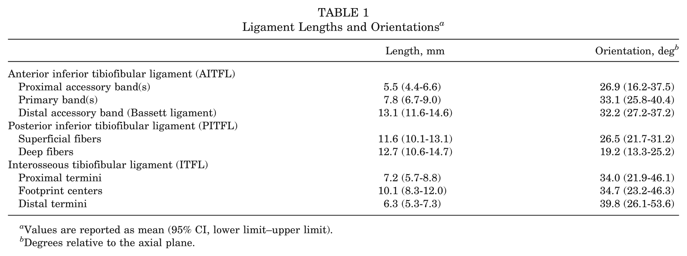
Values are reported as mean (95% CI, lower limit–upper limit).
Degrees relative to the axial plane.
Quantitative Anatomic Features of the Anterior Inferior Tibiofibular Ligament (AITFL) a
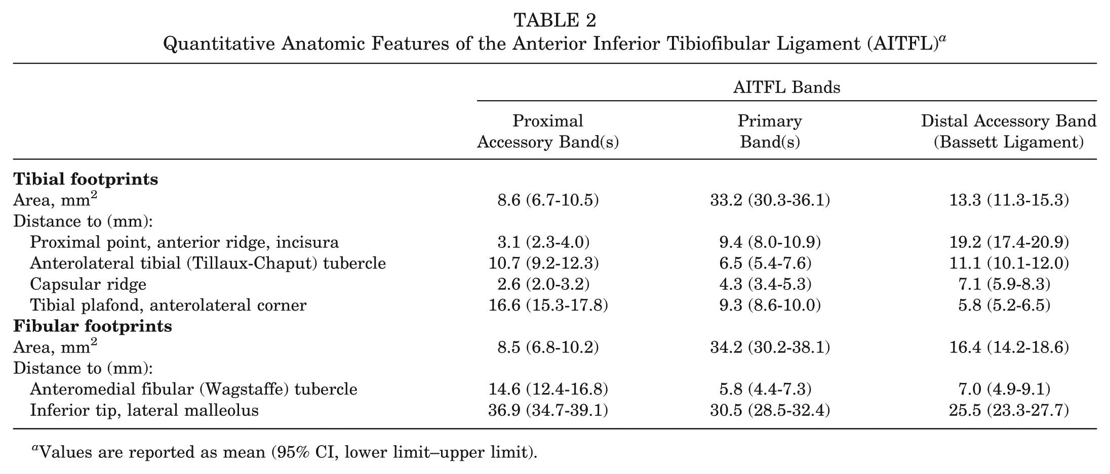
Values are reported as mean (95% CI, lower limit–upper limit).
Quantitative Anatomic Features of the Posterior Inferior Tibiofibular Ligament (PITFL) a
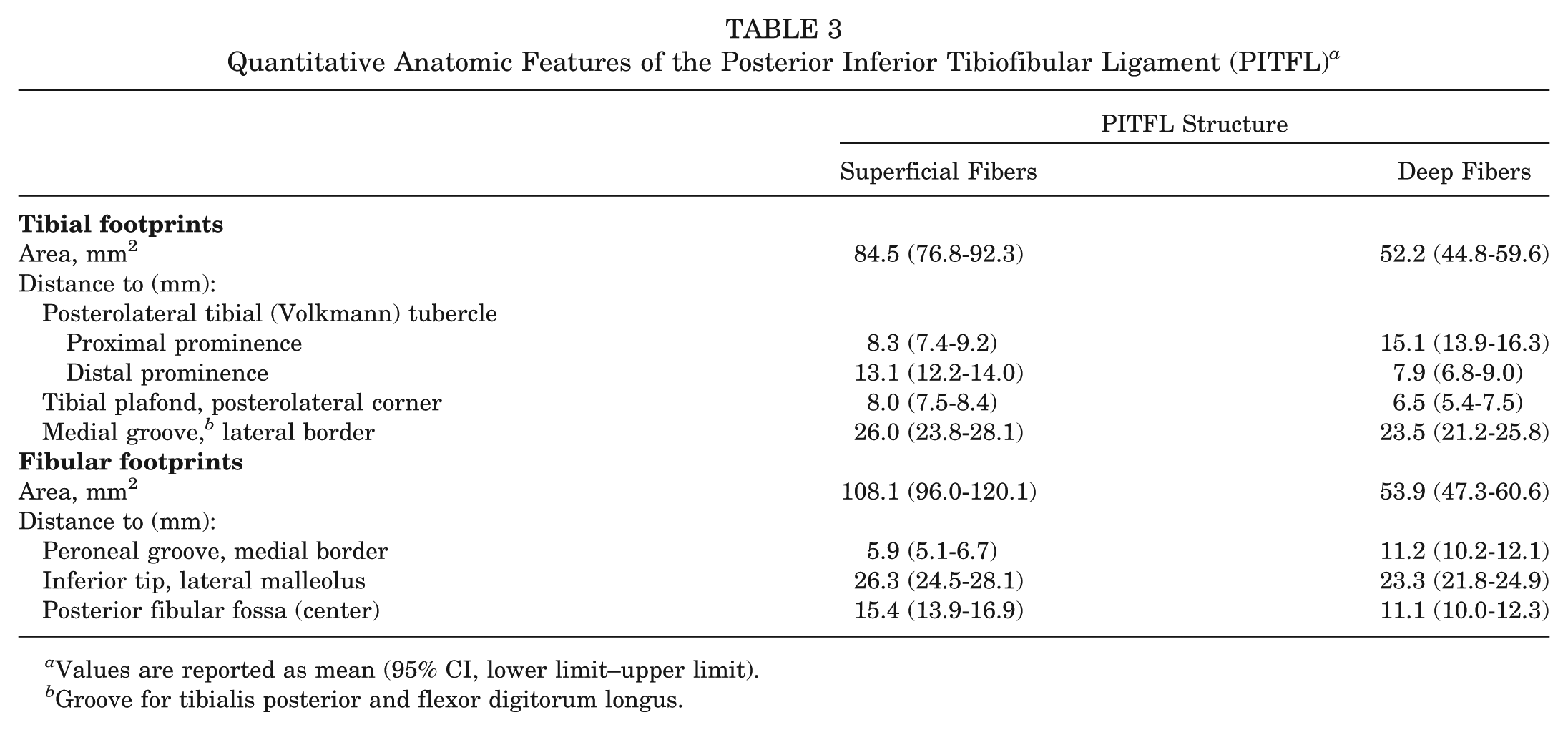
Values are reported as mean (95% CI, lower limit–upper limit).
Groove for tibialis posterior and flexor digitorum longus.
Quantitative Anatomic Features of the Interosseous Tibiofibular Ligament (ITFL) a
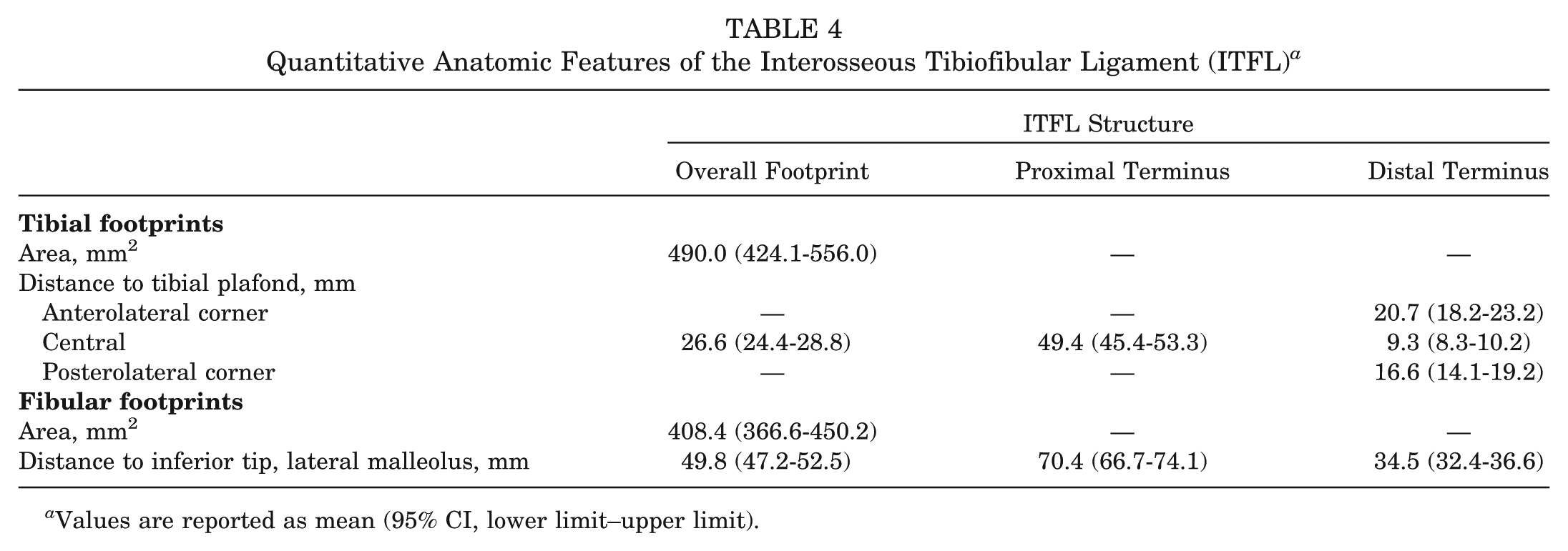
Values are reported as mean (95% CI, lower limit–upper limit).
Quantitative Anatomic Features of the Synovial Recess a
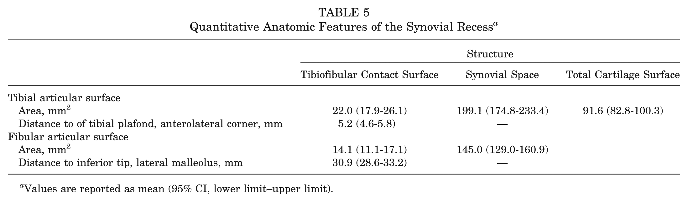
Values are reported as mean (95% CI, lower limit–upper limit).
Anterior Inferior Tibiofibular Ligament
The AITFL was identified in all specimens (Table 2 and Figures 1-4). Specimens had a minimum and median of 3 bands (range, 3-5 bands) that attached along the distolateral border of the anterolateral tibial (Tillaux-Chaput) tubercle and coursed distally and laterally to attach along the anterior border of the fibula. Collectively, the course of the bands was trapezoidal in shape with shorter accessory bands proximally and longer, denser primary bands distally. The distal fascicle of the AITFL, the Bassett ligament, was identified in all specimens and coursed across the anterolateral aspect of the tibiotalar joint. The center of the primary AITFL tibial footprint was 9.3 mm superior and medial to the anterolateral corner of the tibial plafond and the fibular footprint center was 30.5 mm superior and anterior to the inferior tip of the lateral malleolus.
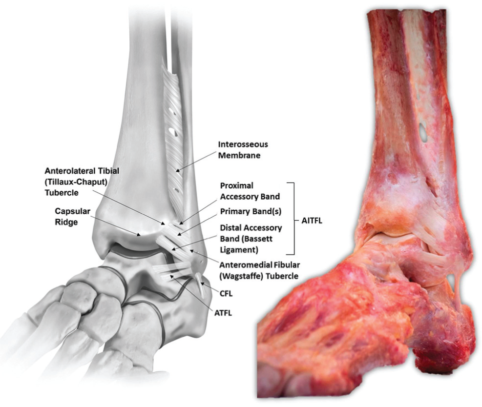
Anterolateral view of a left foot and ankle in neutral plantar flexion and dorsiflexion depicting the anatomic sites of attachment and course of the anterior inferior tibiofibular ligament (AITFL). The capsular ridge is defined as the ridge along the anterior tibia coincident with the superior attachment of the anterior joint capsule. ATFL, anterior talofibular ligament; CFL, calcaneofibular ligament.
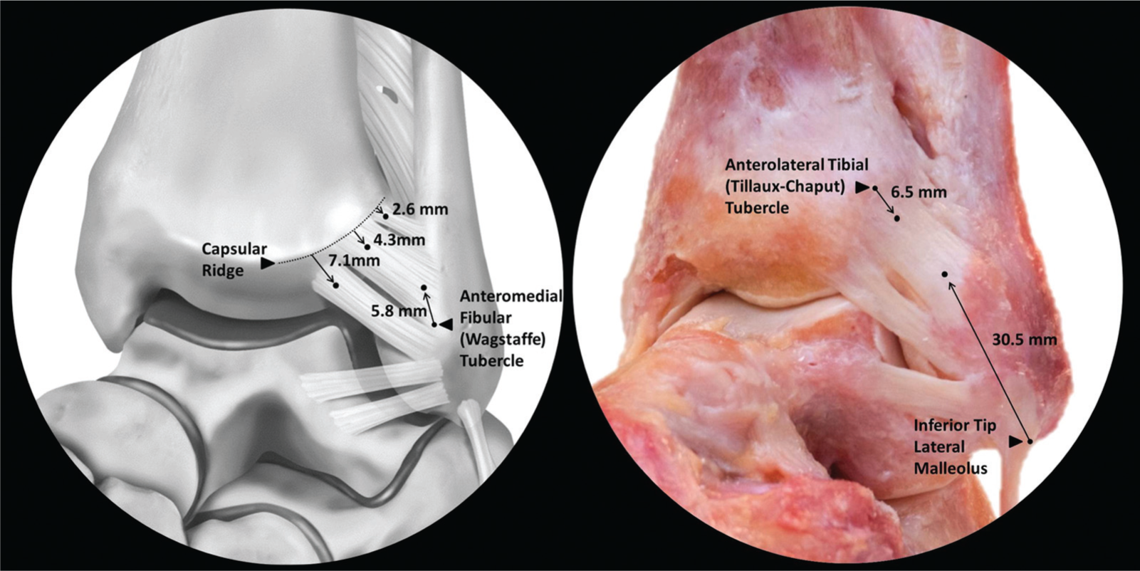
Anterolateral view of a left foot and ankle depicting the attachment sites of the individual anterior inferior tibiofibular ligament (AITFL) bands. Left: Illustration demonstrating footprint distances from the capsular ridge and the anteromedial fibular (Wagstaffe) tubercle. Right: Dissection photograph showing distances of primary AITFL band(s) from the anterolateral tibial (Tillaux-Chaput) tubercle and the inferior tip of the lateral malleolus. From superior to inferior: proximal accessory band(s), primary band(s), distal accessory band (Bassett ligament).
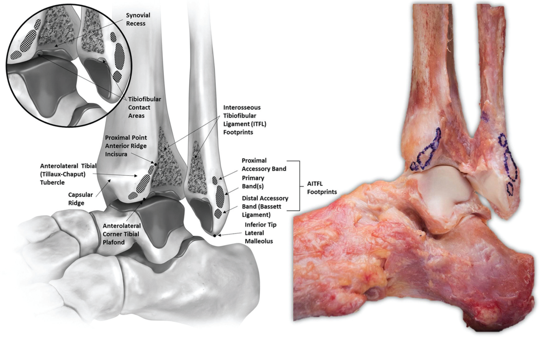
Anterolateral “open book” view of a left foot and ankle in neutral plantar flexion and dorsiflexion. The anterior inferior tibiofibular ligament (AITFL) has been sharply transected at the level of the cortical bone and the footprints have been outlined in surgical marking pen. The interosseous tibiofibular ligament (ITFL) fibers have been severed midsubstance, and the fibula has been externally rotated to expose the ITFL footprints, synovial-lined joint space, and articular cartilage of the syndesmosis.
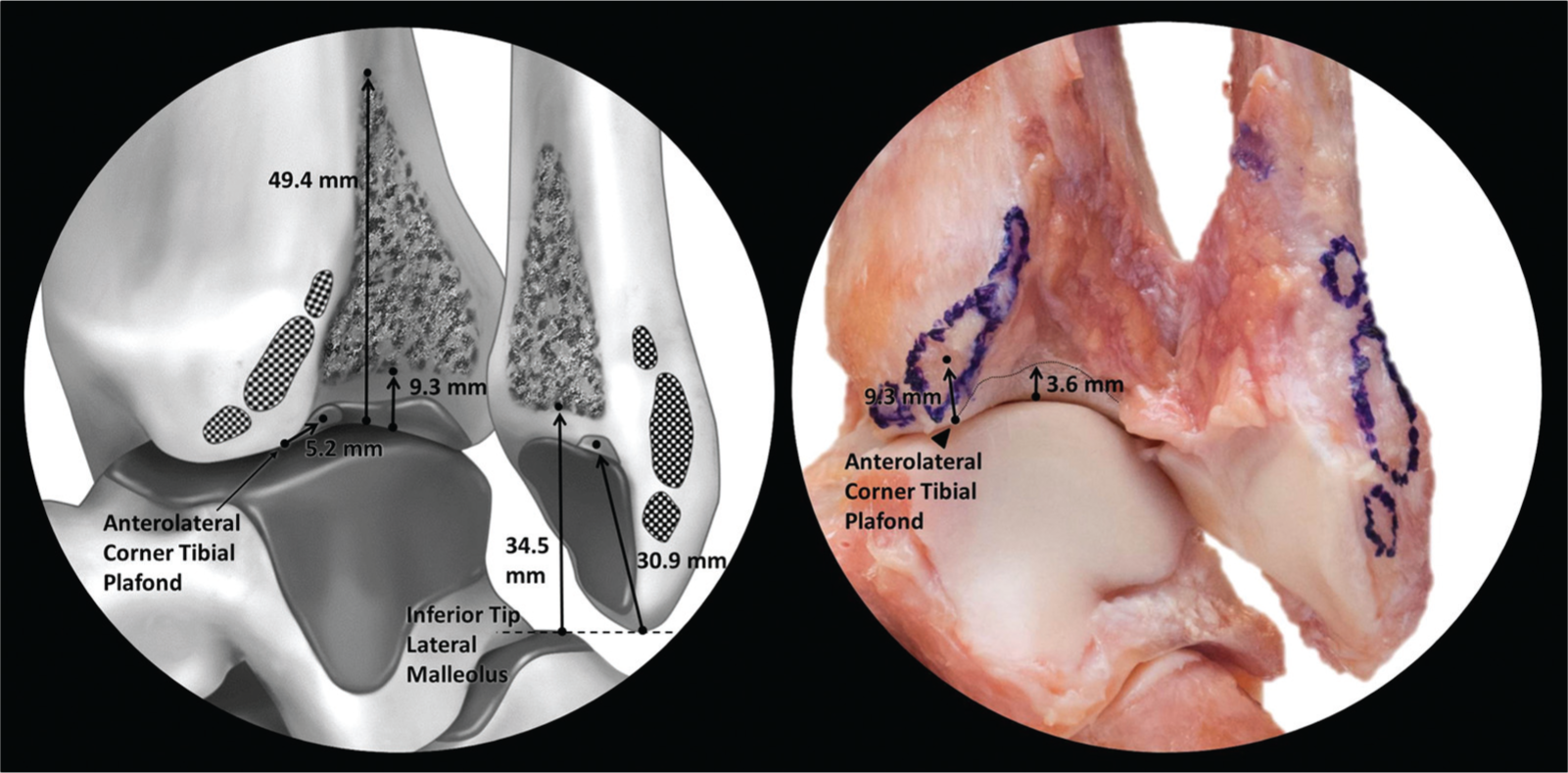
Anterolateral “open book” view of the distal tibiofibular syndesmosis (left foot and ankle) demonstrating the spatial relationships of clinically relevant syndesmotic structures. Left: Illustration depicting the interosseous tibiofibular ligament attachments and articular cartilage of the tibiofibular contact areas and their respective distances from aspects of the tibial plafond and inferior tip of lateral malleolus. Right: Dissection photograph showing the anterior inferior tibiofibular ligament attachments and tibial cartilage and their respective distances from aspects of the tibial plafond.
Posterior Inferior Tibiofibular Ligament
The PITFL was observed in all specimens (Table 3 and Figures 5-7). The PITFL had a trapezoidal appearance with superficial fibers attaching broadly along the distolateral margin of the posterolateral tibial (Volkmann) tubercle and blending medially across the posterior cortical surface of the tibia. The centers of the superficial tibial and fibular footprints were 8.0 mm from the posterolateral corner of the tibial plafond and 26.3 mm from the inferior tip of the lateral malleolus, respectively. The deep fibers, referred to as the inferior transverse tibiofibular ligament, were found in all specimens. The deep fibers were denser and had a condensed, oval-shaped attachment site. The attachment site of the deep fibers along the tibial plafond was 8.0 mm (95% CI, 7.1-8.8 mm) distal, medial, and slightly anterior to the center of the superficial attachment and coursed parallel to their superficial counterparts to attach to the fibula 7.8 mm (95% CI, 6.8-8.9 mm) anterior and distal to the superficial attachment, immediately proximal to the posterior fibular fossa.
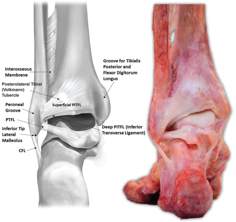
Posterior view of a left foot and ankle in neutral plantar flexion and dorsiflexion diagramming the anatomic sites of attachment and course of the posterior inferior tibiofibular ligament (PITFL). CFL, calcaneofibular ligament; PTFL, posterior talofibular ligament.
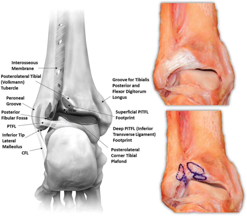
Posterior and inferior view of a left foot and ankle in neutral plantar flexion and dorsiflexion depicting the anatomic sites of attachment of the superficial and deep fibers of the posterior inferior tibiofibular ligament (PITFL). The PITFL has been sharply transected at the level of the cortical bone, and footprints have been outlined with surgical marking pen. CFL, calcaneofibular ligament; PTFL, posterior talofibular ligament.
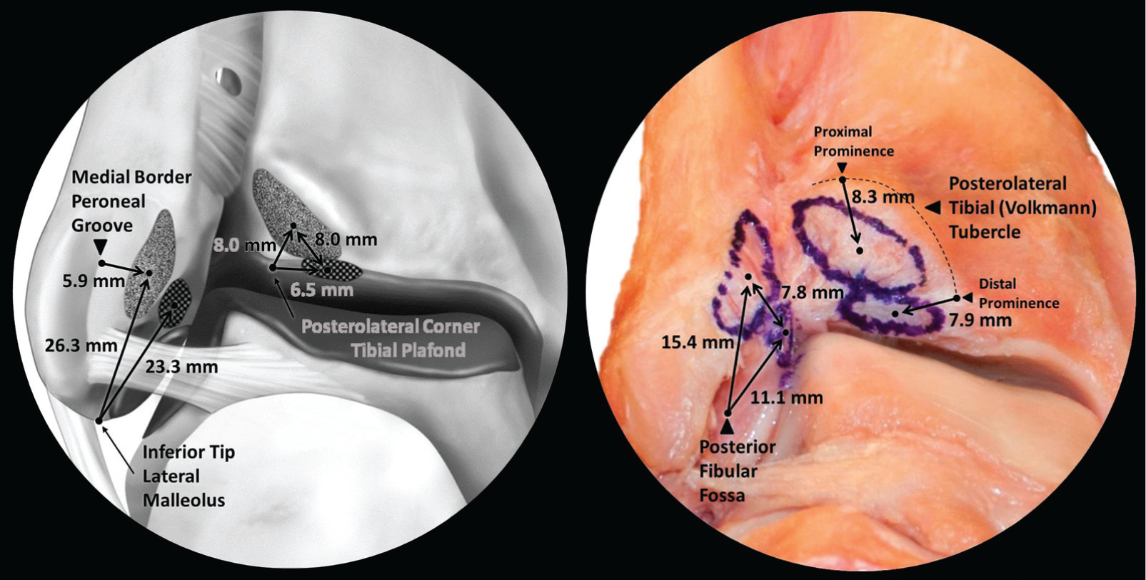
Posterior and inferior view of a left foot and ankle showing the anatomic sites of attachment for the superficial and deep constituents of the posterior inferior tibiofibular ligament (PITFL). Left: Illustration depicting the superficial and deep PITFL footprints in reference to the inferior tip of the lateral malleolus, the medial border of the peroneal groove, and the posterolateral corner of the tibial plafond. Right: Dissection photograph showing the superficial and deep PITFL attachments and their respective distances from the posterior fibular fossa and the posterolateral tibial (Volkmann) tubercle.
Interosseous Tibiofibular Ligament
The ITFL was identified in all specimens (Table 4, Figures 3 and 4). The ITFL was a pyramidal ligamentous network of fibers and intercalating adipose tissue originating from the distal expansion of the interosseous membrane 49.4 mm proximal to the center of the plafond on the tibia and 70.4 mm proximal to the inferior tip of the lateral malleolus on the fibula. Distally, fibers terminated along the superior border of the synovial recess 9.3 mm proximal to tibial plafond and 34.5 mm superior to the inferior tip of the lateral malleolus. The majority of fibers coursed distolaterally from the tibia to the fibula; however, a few of the more superficial fibers coursed in the opposite direction.
Synovial Recess/Tibiofibular Contact Areas
A synovial-lined joint space was identified in all specimens (Table 5, Figures 3 and 4). The synovial recess began at the tibiotalar joint line and extended proximally to the distal border of the ITFL. The anterior and posterior borders of the recess were defined by the osseous ridges of the incisura fibularis tibiae, which was concave in all specimens with a maximum depth of 4.7 mm (95% CI, 3.9-5.5 mm). Distally, an area of tibial articular cartilage was identified in all specimens that extended 3.6 mm (95% CI, 2.8-4.4 mm) proximally from the lateral extent of the tibial plafond. In 14 of the 16 (87.5%) specimens, there were corresponding tibial and fibular articulating cartilage facets at the anterior-most aspect of the distal tibiofibular intersection. These surfaces of direct tibiofibular articulation along the anterior portion of the tibiofibular joint line were located 5.2 mm posterior to the anterolateral corner of the tibial plafond. These facets had mean anterior-posterior and superior-inferior dimensions of 7.9 mm (95% CI, 6.9-8.8 mm) and 4.3 mm (95% CI, 3.9-4.7 mm), respectively, as measured by the tibial cartilage facet of the articulation. In the 2 specimens in which direct contact was not observed, similarly oriented cartilage facets were observed; however, they were separated by a fold of synovial tissue originating from the fibula.
Discussion
The most significant findings of this study were that the syndesmotic ligaments were uniform in location and sites of attachment and that the distal tibiofibular joint was a synovial-lined joint with articular cartilage.
The findings in this study were consistent with previous qualitative anatomic descriptions.1,13 Bartonicek 1 described a multifascicular AITFL, a PITFL with both superficial and deep transverse components, a pyramidal ITFL, and tibiofibular contact areas in 23 of 30 specimens. Ebraheim et al 13 reported 3 to 4 AITFL bands, a PITFL with superficial and deep transverse ligament constituents, and a pyramidal ITFL. In comparison, the current study described a multifascicular AITFL with proximal accessory, primary, and distal (Bassett) bands; a trapezoidal PITFL with superficial and deep fibers; a pyramidal ITFL; and an area of tibiofibular contact in 14 of 16 (87.5%) specimens. Our ligament lengths, however, were overall shorter than those previously reported. Discrepancies can likely be attributed to differences in measurement methods. Bartonicek 1 and Ebraheim et al 13 used digital calipers to measure superficial ligament length, which may have led to longer recorded ligament lengths because the superficial fibers tend to blend across the surface of cortical bone. 41 In contrast, we calculated the 3D spatial relationships between footprint centers, which may be more accurate and reproducible representations of the overall ligament length and may provide greater clinical applications including selection of graft length for a reconstruction. With respect to dimensions of the interosseous ligament, the present data are consistent with the findings of both previous studies. Bartonicek 1 described an attachment beginning 4 to 5 cm above the joint line and extending distally 1 to 1.5 cm above the plafond, while Ebraheim et al 13 reported corresponding measurements of 32.43 ± 4.11 mm and 8.10 ± 3.35 mm, respectively. The present study found the ITFL to originate 49.4 mm and terminate 9.3 mm proximal to the central aspect of the tibial plafond.
With respect to prior biomechanical studies, the results of the present anatomic analysis are generally consistent with previously described ultimate failure strengths of individual structures. Based on the footprint areas, the combined AITFL bands (tibia, 55.1 mm2; fibula, 59.1 mm2) were the smallest of the 3 syndesmotic ligaments by a substantial margin. The tibial (136.7 mm2) and fibular footprints (162.0 mm2) of the combined superficial and deep PITFL constituents were the second largest of the three, while the ITFL fibers were found across the largest area with tibial (490.0 mm2) and fibular attachment areas (408.4 mm2) more than twice the combined footprints area of the PITFL. These areas are largely proportional to relative strength and stiffness values as recent biomechanical studies have demonstrated that the stiffness and ultimate failure of the ITFL are significantly greater than those of the AITFL and PITFL.6,21
However, the relative ligament footprint areas did not appear to predict individual ligament contributions to overall syndesmotic stability as defined by previous biomechanical cutting studies. Ogilvie-Harris et al 37 quantified individual ligament contributions through sequential cutting and measuring of the lateral traction force required to achieve 2 mm of diastasis. 37 The investigators reported that the AITFL contributed 35%, the ITFL contributed 22%, and the combined superficial and deep PITFL contributed 42% of the total syndesmotic stability. Furthermore, Rasmussen et al 40 demonstrated that the AITFL, when intact, provides significant resistance to increases in external rotation. Given these results, it would seem that the combination of location and physiologic orientation, rather than ultimate strength, determines contributions to syndesmotic stability. For example, the ITFL is the strongest, yet its central location and springlike laxity at rest allow for significant physiologic motion of the articulation and therefore it is not the primary contributor to syndesmotic stability as defined by Ogilvie-Harris et al 37 and Rasmussen et al. 40
In the case of syndesmotic injury, the decision to operate has been dictated largely by the degree of instability.11,14 This has been determined primarily through routine and stress radiographs.11,14,18,23 The combination of anatomic detail, such as the information provided in this study, biomechanical studies, and improved imaging techniques, may help establish a more effective diagnostic and treatment algorithm. When surgical treatment is indicated, transosseous fixation including syndesmotic screws or cortical fixation suture-button constructs is the current standard of care, although in chronic cases, reconstruction of the ligaments may be performed.12,16,27,32,33 Optimally, fixation devices are currently inserted in line with the neutral anatomic plane (approximately 30° posterior to the coronal plane), parallel to the plafond, 2 to 5 cm proximal to the joint line while reduction forceps are placed on the lateral malleolar ridge of the fibula and central point of the medial tibial cortex.3,29,31,38 Based on the presented anatomic data, such placement is within the tibial and fibular ITFL footprints and safely avoids the synovial-lined joint space including the articulating cartilage of the tibia and fibula. However, such placement may not optimally restore ligament footprints and native syndesmotic anatomic characteristics. Specifically, the defined locations of the ITFL fibers and articular surfaces suggest that fixation can be implemented more distally while still safely avoiding iatrogenic damage to the synovial recess and articular surfaces. The present study found that the ITFL tibial fiber attachments begin 49.4 mm proximal to the tibiotalar joint line and terminate 9.3 mm proximal to the central aspect of the tibial plafond, with an ITFL footprint center 26.6 mm above the lateral extent of the tibial plafond.
We acknowledge the inherent limitations of the current cadaveric anatomic investigation. Foremost, we used a relatively small sample size; however, the use of nonpaired specimens provides additional sample heterogeneity and anatomic variation. Furthermore, the relatively narrow ranges of our confidence intervals suggest that the sample size was sufficient for the observed variability. Specimens also had a mean age of 59.6 years, which is older than the typical athletic population that would undergo operative treatment for syndesmotic injury. However, we believe that degenerative changes and their influence on the data were minimized through screening specimens for previous injury, surgery, osteoarthritis, and gross anatomic derangements. We recognize the potential for errors in dissection, structure identification, and data collection. However, this study used a single observer (B.T.W.) under the direct instruction of a senior foot and ankle fellowship–trained orthopaedic surgeon (T.O.C.) to control for any confounding interobserver variability. Although the use of a single observer precludes any intraobserver agreement assessment, we believe that given the scale of the reported measurements, multiple observers would have introduced variability that was not an accurate reflection of the actual quantitative differences between specimens. We acknowledge that differences in footprint identification may exist among observers, and the results must be interpreted accordingly. However, we used a reproducible and thoroughly described method and believe that the results reported are an accurate reflection of both the quantitative and qualitative anatomic characteristics of the syndesmosis.
Conclusion
The 3 syndesmotic ligaments (AITFL, ITFL, PITFL) were identified in all specimens and had consistently located origins and insertions surrounding cartilage-covered facets at the distal tibiofibular articulation. Quantitative locations of ligament attachments and footprint areas were carefully measured and may provide the basis for future biomechanical testing. Localized osseous references may help optimize diagnostic imaging and surgical techniques, reduce the risk of iatrogenic articular damage from misplaced surgical implants, and provide quantitative data for the development of anatomic reconstructions.
Footnotes
Acknowledgements
The authors acknowledge Andy Evansen for the anatomic illustrations, Barry Eckhaus and Angelica Wedell for specimen photographs and assistance with figure images, and Kelly Adair for acquisition of surgical supplies and expertise.
One or more of the authors has declared the following potential conflict of interest or source of funding: R.F.L. is a paid consultant for Arthrex Inc and receives research support from Arthrex, Smith & Nephew, Ossur, and Linvatec. T.O.C. is a paid consultant for Arthrex Inc and Stryker and serves as a lecturer on speakers bureaus for Arthrex, SBI, Smith & Nephew, and Stryker.