
Abstract
The application of three-dimensional printing technologies to metal materials allows us to design innovative, low-weight, patient-specific implants for orthopedic prosthesis. This is particularly true when the reconstruction of extensive metastatic bone defect is planned. Modeling complex three-dimensional-printed highly repetitive trabecular-like structures based on finite elements is computationally demanding, while homogenization algorithms offer the advantage of reduced simulation cost and time, allowing an effective evaluation of new personalized design suitable for clinical needs. This article describes and discusses the implementation of a reliable method for the multiscale modeling of trabecular structures by means of asymptotic expansion homogenization. Following the material characterization of the Ti6Al4V alloy obtained by electron beam melting technology, the asymptotic expansion homogenization was applied to two alternative low-density cell-unit designs. Model predictions demonstrated satisfactory agreement with compressive experimental tests and cantilever bending tests performed on both designs (differences lower than 5.5%). The method was extended to a real patient-specific hemipelvis reconstruction, exploiting the capability of the asymptotic expansion homogenization approach in quantitatively describing the effect of cell-unit designs and three-dimensional-printing stack direction (i.e. cell-unit orientation) both on the overall mechanical response of the implant and on the stress distribution. The hemipelvis implant filled with the higher density cell unit demonstrated to be 14% stiffer than using the lower density one, while changing the cell-unit orientation affected the stiffness up to 10%. The maximum stress values reached at the anchors were affected in a minor extent by the investigated design parameters.
Keywords
Introduction
Rapid prototyping (RP) is an innovative layer-by-layer manufacturing process that is used to fabricate a three-dimensional (3D) object starting from a computer-aided design (CAD) interface. The introduction of 3D printing technologies has widened the frontiers of traditional orthopedic implants.1–3 Compared to conventional modular implants obtained by forgings or machining of semifinished (e.g. extruded) parts, additive manufacturing technologies allow a significant reduction in terms of time and cost. 2 Moreover, new 3D-printed custom-made prosthesis promises to adapt to the specific exigence of each patient to be treated. In this light, complex revision surgeries, treatment of large bone defects, spine arthrodesis and/or reconstruction, and the treatment of patients affected by bone metastases represent ideal field of application.4–8
The most significant step forward is represented by the freedom to design arbitrary geometries. While primary stability could be based on traditional anchoring systems (e.g. solid parts coupled to bone screws), the usage of trabecular structures could decrease the overall weight of the prosthesis, also avoiding stress shielding. In fact, it would be possible to optimize the geometrical parameter of porous structures to match the elastic properties of human bone.9,10 Moreover, secondary stability or osseointegration could be enhanced using an optimized trabecular microstructure at the interface with bone, capable of promoting a favorable bone ingrowth. To achieve these results, a better understanding of microstructural design parameters is required. In particular, it is necessary to design a 3D-printed regular lattice with optimized characteristics in terms of porosity, stiffness, and mechanical strength.10–14 The implications of such complex structure on the prosthesis biomechanics should pass through an accurate numerical analysis.
A special attention must be paid on the complexity and computational cost of the simulation, especially when dealing with implants that incorporate a scaffold design into their structure. In fact, such geometries require high number of mesh elements to discretize the geometry, which reflects in high computational time. 15 To overcome this limitation, since most scaffolds follow a periodic structure, it is possible to apply a well-known numerical method specifically designed to take advantage of this fact.15–17
The aims of this work are to (1) focus on geometrical and mechanical non-idealities associated with 3D printing and (2) suggest a reliable workflow, validated with experimental tests, capable of describing the elastic behavior of periodic trabecular-like structures. Namely, a homogenization approach to reduce the cell unit (representative volume element or RVE) to a continuum scale is applied to two alternative lattice structures used as filling of a hemipelvis patient-specific design. The rest of the article is organized as follows. The “Materials and methods” section describes the experimental characterization of the 3D-printed Ti alloy, followed by a brief description of the homogenization technique used to obtain the effective mechanical properties of the scaffold. The obtained effective properties are validated against compression and cantilever bending. Finally, the identified effective properties were applied to model a patient-specific hemipelvis design.
Materials and methods
To reduce the computational cost needed to run simulations on materials with periodic 3D-printed trabecular metal structures, effective mechanical properties were determined by means of a well-established homogenization procedure.15,16 For a correct algorithm implementation, the RVE must be characterized in terms of material response at the microscale and microstructural morphology, while the capability of the model in predicting the effective mechanical response of a real 3D-printed structure will be verified and validated by comparison with experiments.
Experimental characterization
To characterize the mechanical response of 3D-printed bulk material and the morphology of simple trabecular structures, dog-bone specimens in Ti6Al4V ELI (grade 23) were produced by Adler Ortho SPA (Cormano, Italy) using an electron beam melting (EBM) system (Arcam, Mölndal, Sweden).
Characterization of elastic material properties at the macroscale
To characterize the elastic mechanical properties of the bulk material, uniaxial tensile tests were performed at the macroscale. Three specimens with cross-section 6 mm × 4 mm and gage length of 5 cm were used. An MTS 858 MiniBionix testing machine (MTS System Inc., Minneapolis, MN, USA) was used in displacement control at 2 mm/min loading and unloading the specimen within the linear-elastic range, while a biaxial MTS 632.11C-20 extensometer (MTS System Inc.) monitored the longitudinal and transverse strains on the free length of the specimen (Figure 1). The tensile elastic modulus (E) was calculated as the slope of the stress–strain curve, while Poisson ratio (ν) was obtained dividing the longitudinal strain by the transverse one multiplied by minus one.
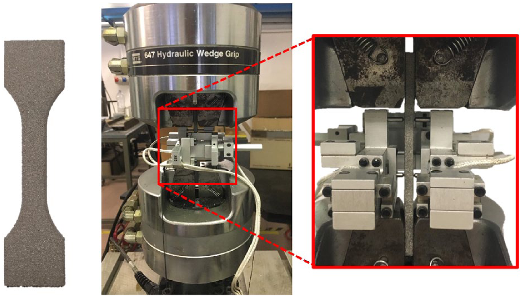
Characterization of the bulk elastic properties of a dog-bone specimen through uniaxial tensile test (left) and details of the gage length instrumented with a biaxial extensometer (right).
Characterization of superficial morphology at the microscale
To characterize the effective morphology of the 3D-printed trabecular structure at the microscale, that is, scale of the trabecula, two types of dog-bone specimens with a squared cross-section were prepared (Figure 2): nominal dimensions were 0.5 mm × 0.5 mm (type A) and 0.75 mm × 0.75 mm (type B), respectively, with a gage length of 10 and 15 mm. These cross-section dimensions correspond to the standard dimensions currently used by Adler Ortho SPA for their commercial applications and were chosen for convenience. The external surface of two specimens per type was scanned using a 3D laser confocal microscope (LEXT OLS4100; Olympus, Tokyo, Japan) with 5× and 10× magnification lenses to analyze the effective size of the trabeculae (deff).
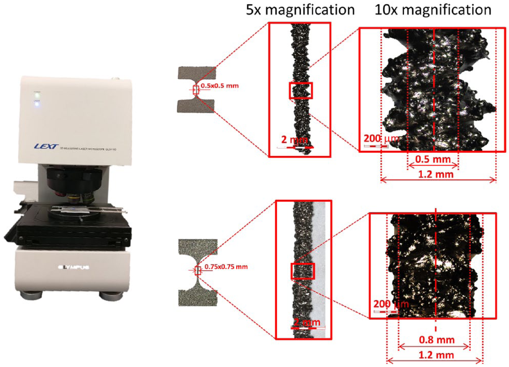
Characterization of the effective morphology of the trabecular specimens using confocal laser microscopy: the nominal dimensions of type A (top) and B (bottom) trabeculae were 0.5 and 0.75 mm, respectively.
Model calibration and validation
Two low-density open-cell trabecular designs (type A and type B, Figure 3) were considered as alternative fillings of commercial orthopedic implants. The CAD drawings of the RVEs or cell units with a nominal trabecular size of 0.5 mm × 0.5 mm (type A) and 0.75 mm × 0.75 mm (type B) provided by Adler Ortho SPA were parameterized in SolidWorks (Dassault Systèmes SolidWorks Corp., Waltham, MA, USA). Being the effective size of the trabecula for each design (deff) highly dependent on several 3D-printing processing parameters (e.g. powder size, bed thickness, and temperature),18,19 it was assumed to be the only design parameter varying within the range observed during the previous morphological analysis on microscale samples. All the remaining design parameters were considered equal to their nominal dimensions. The cell units were then imported in Abaqus 2017 (Dassault Systèmes Ri, Simulia Corp. Providence, RI, USA) for discretization using linear tetrahedral elements and subsequent simulation.
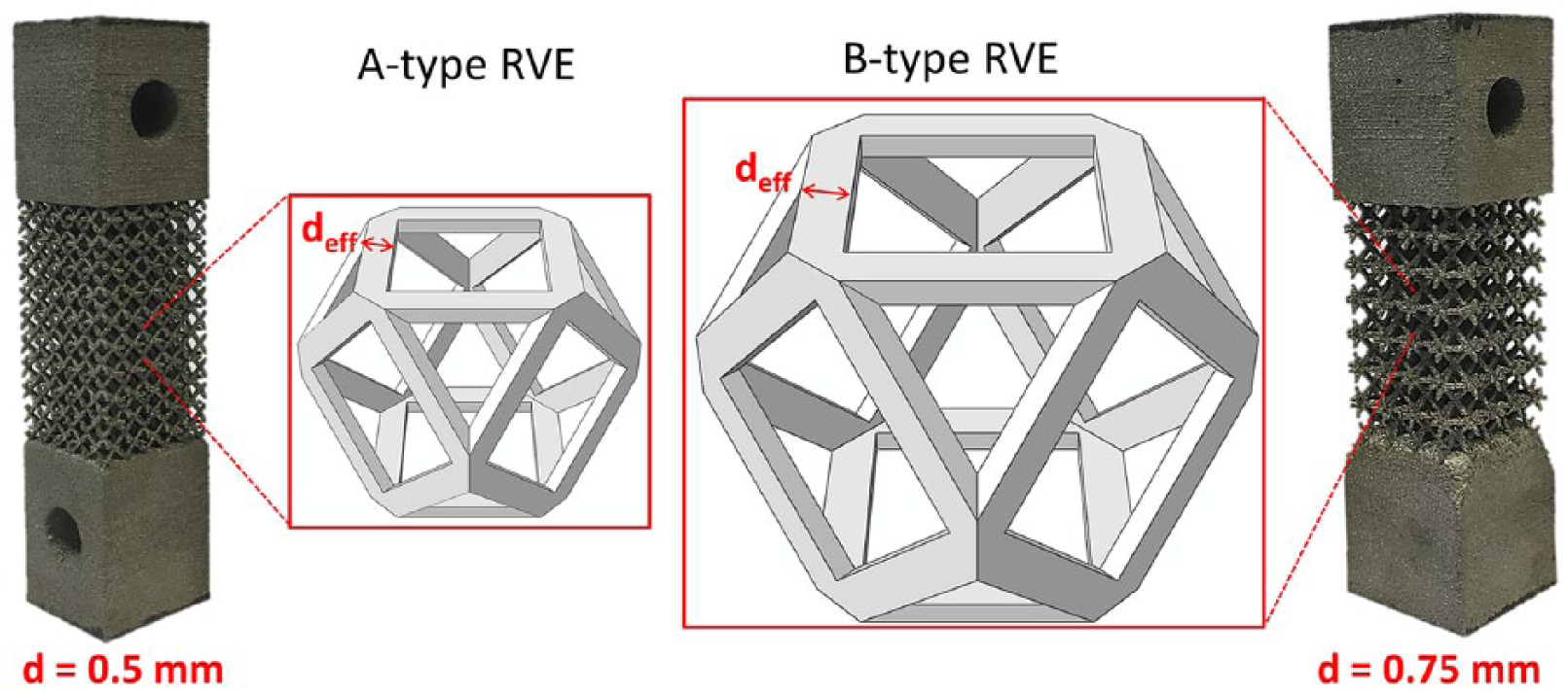
Real trabecular samples used for the experimental characterization in compression and bending with details of the regular cell units (RVE) with effective square cross-section assumed for the homogenization algorithm.
An elasticity-based approach procedure based on the asymptotic expansion homogenization (AEH) theory,20–22 which accounts for the periodicity of the underlying RVE and a symmetric behavior in tension and compression, was implemented as a user subroutine in Abaqus 2017. 16 In brief, at the RVE level, the following elasticity equations are solved 16
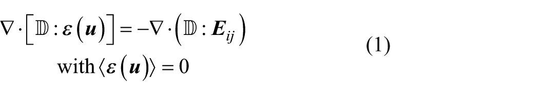
where

Hence, the total field of microstrains

with
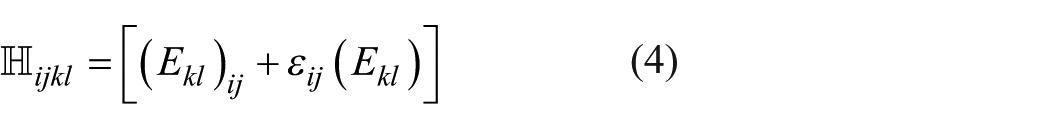
where
where V is the enclosing volume of the RVE and V* the volume of the solid part. The effective stiffness tensor
Three type A and three type B trabecular specimens, having a nominal trabecular size of 0.5 and 0.75 mm, respectively, and a gage length of 23.5 mm × 23.5 mm × 42.3 mm and 27.2 mm × 27.2 mm × 40.8 mm, were printed in Ti6Al4V ELI via EBM (Figure 3). Considering the geometrical variability of the 3D-printed trabecular structure, the effective section dimension (deff) of each RVE was calibrated comparing the results of simple compressive tests to the numerical twin in which the homogenized properties were assigned to the geometry. The calibration was considered to be reached when the difference between computational and experimental tests was less than 2%. Subsequent cantilever tests were used to validate and confirm the reliability of the homogenized approach in predicting the overall mechanical response.
Uniaxial compression
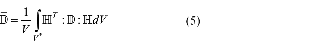
Three specimens were quasi-statically loaded in displacement control within the linear-elastic range using an MTS 858 MiniBionix testing machine (MTS System Inc.). Spherical joint fixtures were used to avoid shear loads (Figure 4) and three loading–unloading cycles were applied to ensure a repeatable elastic response. The compressive stiffness was calculated as the average slope of the third cycle of the force–displacement curve in the range of 2000–4000 N for type A and 800–1400 N for type B specimens where the load–displacement response was linear (Figure 4).
Experimental test set-ups (a) used for the uniaxial compression (top) and cantilever bending (bottom) of the trabecular specimens used, respectively, for the calibration and the validation of the homogenization algorithm. (b) Typical force–displacement curves showing the linear range where the stiffness was evaluated are reported.
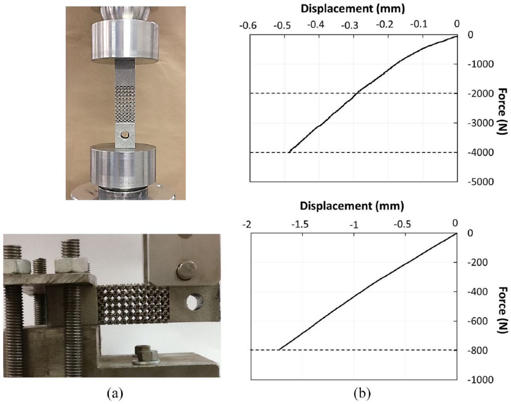
Given the symmetries of the boundary conditions (Figure 5(a)), only 1/8 of the sample was designed in Abaqus and the continuum material properties obtained via homogenization were assigned to its free length. Different homogenized stiffness matrices corresponding to trabecular sizes (deff) in the range previously characterized were obtained. The corresponding resultant compressive stiffness was calculated as the slope of the reaction force–displacement curve and compared to the experimental values for each specimen type.
Numerical models validated with experiments. (a) Representation of the experimental specimen (left) and of the compression model describing 1/8 of its gage length with symmetry planes about X, Y, and Z directions. (b) The cantilever bending model was encastered on the left extremity, while loading was applied on the right on using a cylindrical pin.
To confirm the agreement between experiments and homogenization model, the experimental apparent strain was compared with the computational homogenized strain at the macroscale. Moreover, to justify the applicability of the homogenization algorithm, valid in the linear elastic range, the von Mises microscopic strain distribution was determined at maximum load during compression tests.
Cantilever bending
To verify and validate the overall mechanical response of the homogenized stiffness matrix, a cantilever test was also performed on three specimens. The specimens were gripped at one end through rigid fixtures, while the other end was free and loaded with a steel cylinder using a MTS 858 MiniBionix testing machine (Figure 4, bottom). Three loading–unloading cycles were applied within the elastic range, calculating the flexural stiffness as the average slope of the force–deflection curve in the range of 0–800 N for type A and 0–180 N for type B during the third cycle where the load–displacement response was found to be linear (Figure 4, bottom).
The corresponding CAD (Figure 5(b)) was designed in Abaqus, and the material properties obtained from calibration in compression were assigned to the trabecular structure, while the 3D-printed bulk material properties were assigned to the extremities. The resultant bending stiffness was calculated as the slope of the reaction force–displacement curve and compared to the experimental values for each specimen type.
Application to patient-specific hemipelvis design
To demonstrate the capability of the AEH approach in quantitatively describing the effect of specific parameters of interest, a patient-specific case requiring hemipelvis reconstruction due to extensive bone resorption was considered. Following computed tomography (CT) reconstruction and mirroring, the overall implant design was obtained, where two solid fixtures for bone anchorage were added (Figure 6). The validated homogenized stiffness matrices were assigned as material properties to the implant, which was discretized with 500,910 linear tetrahedrons. A conventional 1 kN concentrated vertical force was applied on a reference point coupled with the internal surface of the acetabular cup, while only the fixtures were assumed to be fully constrained to reproduce a worst-case condition. The maximum von Mises stress on the fixtures and a concentrated parameter, namely the point of the application of the force that was used to evaluate the stiffness of the implant, were considered. The effect of cell unit design was studied by comparing A- and B-type trabecular structures, while the local reference system defining the orientation of the RVE within the implant was three dimensionally rotated to reproduce alternative 3D-printing stack directions.
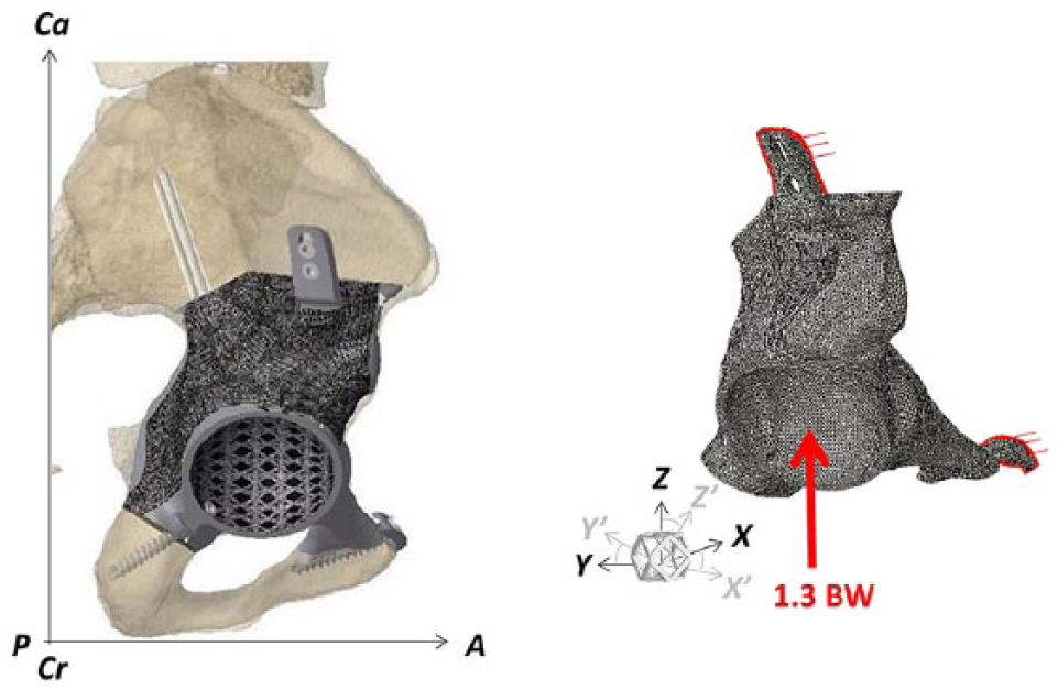
Reconstruction of the custom-made hemipelvis starting from CT data (left) and details of the discretized FEM with homogenized material properties and boundary conditions (right).
Results
Experimental characterization
Characterization of elastic material properties at the macroscale
The tensile elastic modulus of the 3D-printed material resulted to be 97.4 ± 1.4 GPa, whereas Poisson ratio was found to be 0.29 ± 0.03.
Characterization of superficial morphology at the microscale
The morphological analysis demonstrated that the trabecular specimens had an irregular section with an average effective size (deff) different than the nominal one, with values in the range 0.51–1.28 and 0.83–1.27 mm, respectively, for type A and B samples (Figure 2).
Model calibration and validation
Uniaxial compression
The results of the experimental compressive stiffness are reported in Table 1. The mesh sensitivity analysis performed on the type A cell showed convergence of the parameter of interest with an average element size of 0.07. At convergence, the number of elements used to discretize type A and B cells resulted, respectively, in 185,357 and 549,484 elements for each considered RVE.
Calibration of the effective trabecular size (deff) used to determine the homogenized stiffness matrix by comparison with the experimental compressive tests both on type A and B cell units.
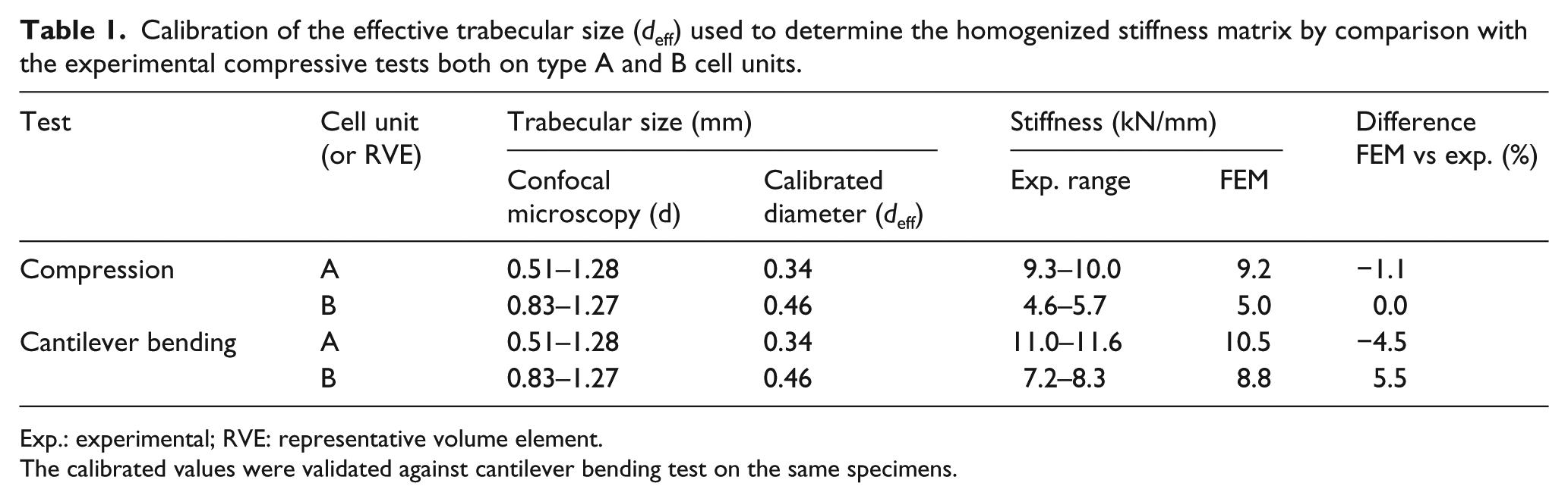
Exp.: experimental; RVE: representative volume element.
The calibrated values were validated against cantilever bending test on the same specimens.
The homogenized stiffness matrix obtained from the calibration of the trabecular cell units showed cubic symmetric characteristics due to the presence of three perpendicular symmetry planes in the RVE; this effect also resulted in an identical material response as the cell unit is rotated 90°, regardless of the considered direction. The calibrated value of deff was found to be equal to 0.34 and 0.46 mm, respectively, for type A and B trabecular structures (32% and 39% smaller than the nominal values). The resulting effective stiffness matrices for both trabecular structures,
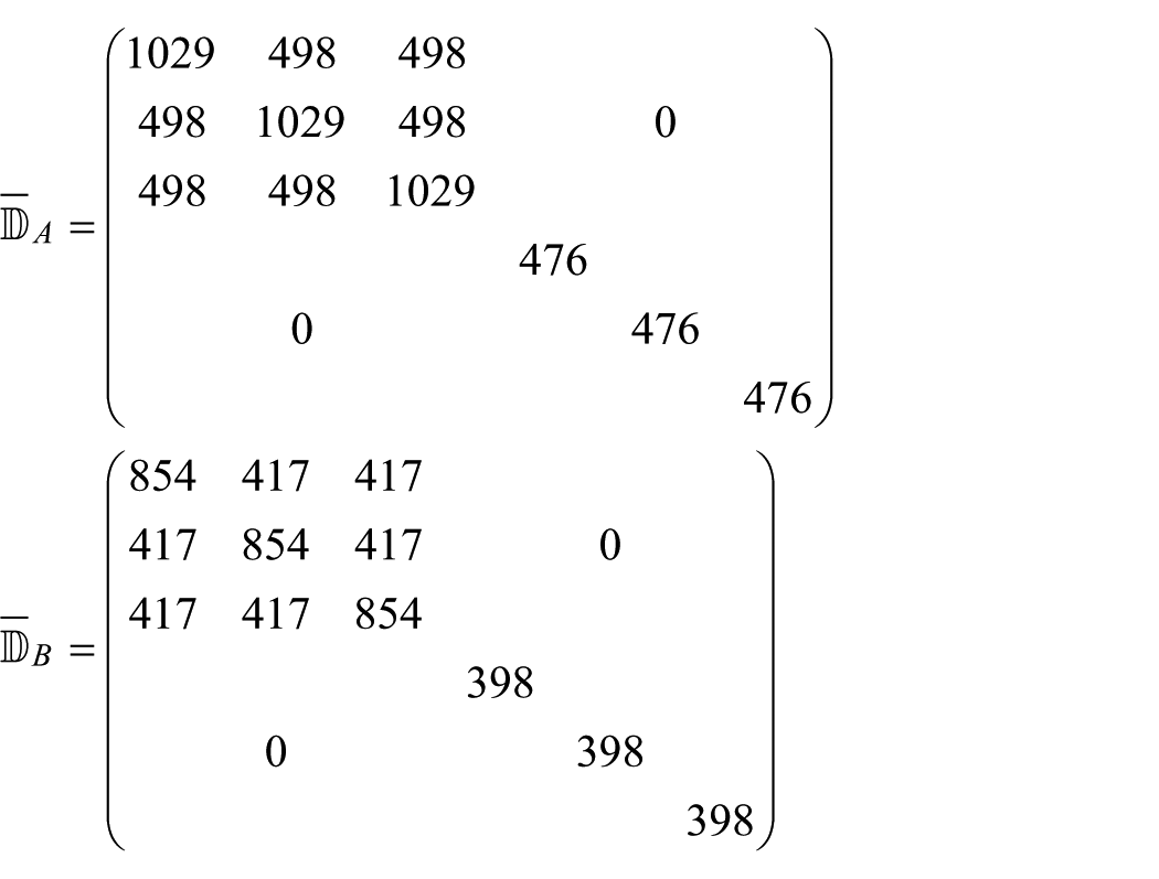
As for type A trabecular unit, increasing deff to 0.5 mm implied an average increase in the stiffness matrix components up to +350%, while decreasing to 0.33 mm determined an average reduction of −6%. As for type B, increasing deff to 0.7 mm determined an average increase in the stiffness matrix components up to +140%, while decreasing to 0.4 mm determined an average reduction of −25%. Percentage difference between FEM and experiment was less than 5.5% in calibration.
The homogenized strain at the macroscale was in perfect agreement with the experimental apparent strain (Table 2). The maximum microscopic von Mises strain never exceeded the expected yielding point2,3 (Figure 7).
Experimental apparent strain obtained during compression tests and principal macro- and microscale strains calculated assuming the calibrated trabecular size (deff).
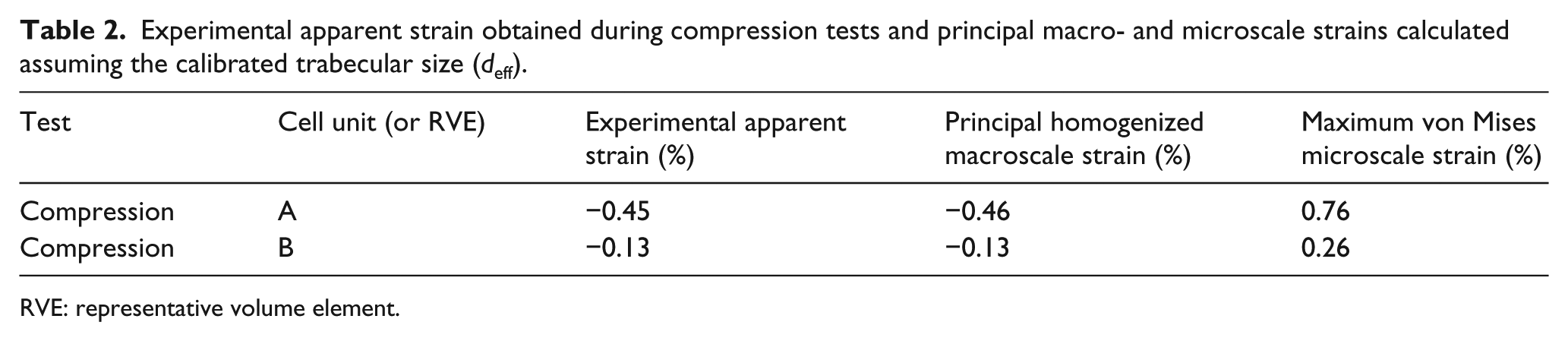
RVE: representative volume element.
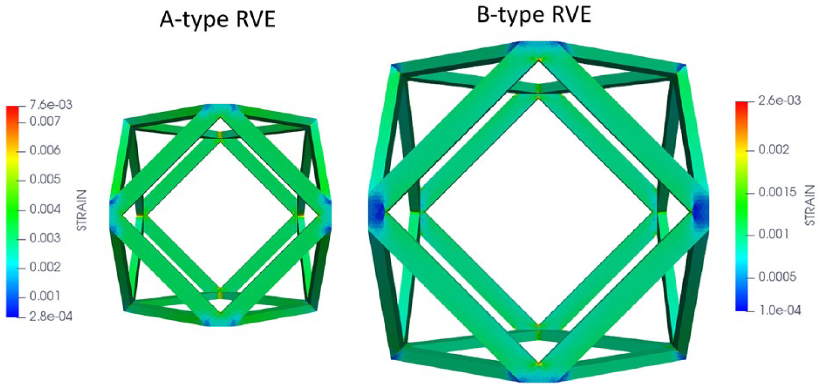
Microscale von Mises strain distribution on the RVEs for compression tests at maximum load for both types A and B (assuming the effective strut size deff obtained from calibration).
Cantilever bending
The experimental tests on the cantilever bending showed elastic response for all loading cycles that superimpose to the curve shown in Figure 4(b) (bottom panel). The homogenized model describes well the bending stiffness of the specimen experimentally loaded with the cantilever bending test. The homogenized model with a type A trabecula underestimated the stiffness by 4.5%, whereas stiffness is overestimated by 5.5% in the case of type B trabecula (Table 1).
Application to patient-specific hemipelvis design
The effect of the cell unit geometry on the overall implant stiffness showed that type A unit was 15% stiffer than type B for a given material orientation (Figure 8). However, minimal differences were found on the von Mises stress values, reaching about 768 MPa on the greater fixture and 340 MPa on the smaller one for both cell units.
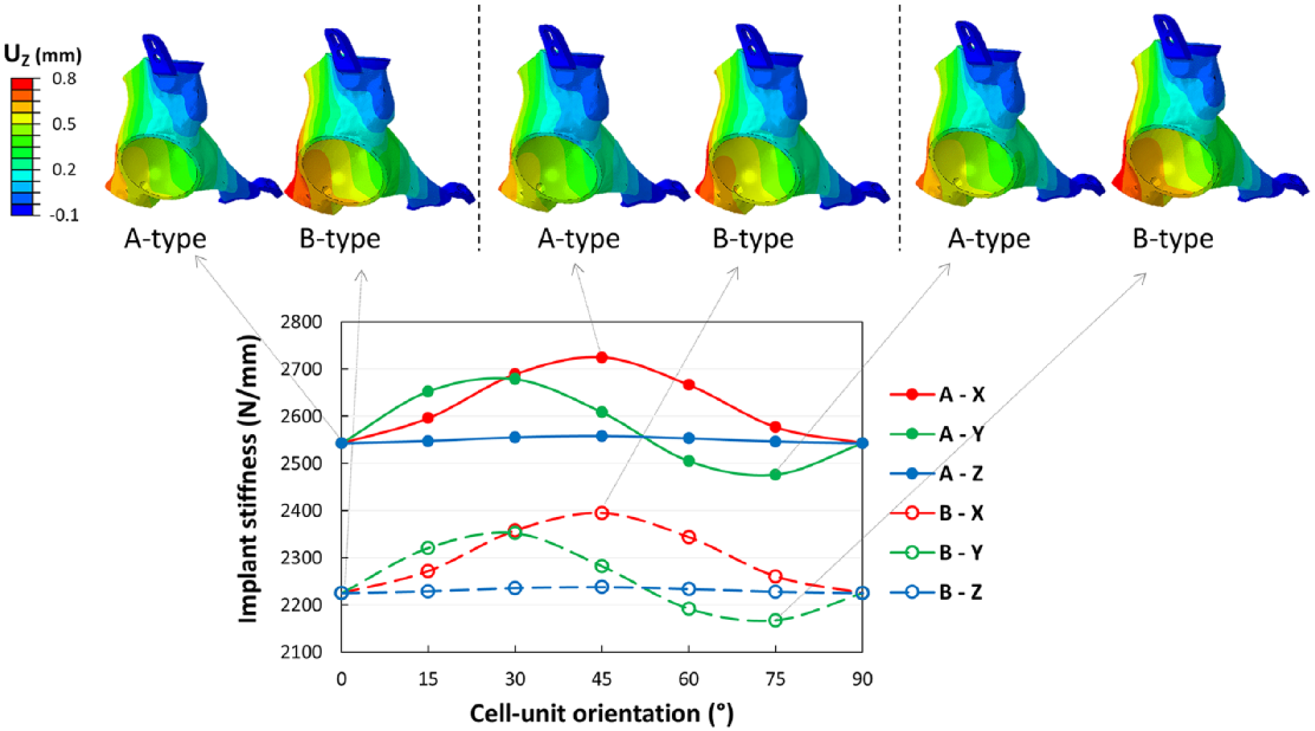
Effect of cell-unit orientation in 3D and cell-unit type on the overall implant stiffness.
Considering the effect of cell-unit orientation on the overall implant stiffness, the largest effect was observed for a variation about the X axis leading to an increase in the overall stiffness of up to 7% both for type A and B cell units (Figure 6). No evident variations were noticed in the maximum von Mises stress value predicted on the greater fixture (range: 766–770 MPa), while variations up to 12% and 16% were observed on the smaller one for type A and B cell units (352 and 356 MPa, respectively).
Discussion
This article reports on the implementation of a reliable workflow capable of describing the effective material properties for trabecular-like scaffolds and the underlying material properties (titanium alloy) by means of the AEH.15,16 Such theory is applied with the aim of reducing the computational cost of the “in-silico” mechanical evaluation. The proposed workflow requires the material characterization of the Ti6Al4V alloy obtained by EBM technology, followed by the computation of the homogenized stiffness matrix describing the mechanical properties of the trabecular structures. With the effective material properties at hand, computer simulations of the patient’s prosthesis can be performed.
The density of the 3D-printed trabecular structures is significantly lower with respect to the actual bone, about 90% void ratio for the EBM cell against 63%–70% for the actual bone. 23 However, it is important to notice that the scope of the design of the EBM cells is to reduce the weight of the prosthesis while keeping the elastic stiffness as close to the actual bone as possible. In the case of a metallic prosthesis it translates in increasing the void ratio without sacrificing mechanical integrity of the structure. The axial and shear stiffness components associated with the two cells were found in the upper bound of the trabecular bone mechanical response (300–500 MPa), whereas the direct components of the stiffness matrix were close to the lower bound of the cortical bone (1.5 GPa). The elastic modulus of the cortical bone is typically two orders of magnitude lower than the modulus of the metallic orthopedic implants. 23 Such discrepancy can lead to bone resorption with the consequent fracture at the implant site. Hence, the use of porous trabecular-like structures allows us to control the density of the implants, which is necessary to obtain prosthesis with weight and mechanical properties close to those of bone and to ensure their osseointegration, avoiding stress shielding.9,24 In addition, the values of the stiffness matrix can be further adjusted by modifying the dimensions of the periodic cell. In this regard, the proposed framework allows us to easily achieve this objective since it can be effectively integrated with optimization algorithms.
Mechanical testing protocols have been designed to characterize the implant at the bulk material and trabecular scale. The bulk material, printed with EBM technology, confirmed to have a slightly lower tensile elastic modulus with respect to the material obtained by traditional mechanical processing, as reported in the study by Wong et al. 25 It is important to notice that we have assumed that the tensile material properties obtained on the bulk material were the same as the 3D-printed strut tested under compression. Since it is established that the mechanical characteristics of many metals are higher in compression than in traction, this may result in an underestimation of the overall behavior of the cell unit in compression. Such an effect may be covered by the calibration step, where the effective strut size was tuned to match the experiments (Table 1). In terms of macroscopic strain, a good agreement between the experimental apparent strain and the principal computational macroscale strain was found (Table 2). Interestingly, the calculated microstrains resulted higher than macrostrains due to the strut-like structure of the trabeculae (Table 2 and Figure 7). This may be critical to identify a potential failure mode for these materials, in particular when subjected to cyclic loading. We also reported the predictive capabilities of the method with a cantilever test (Table 1), where the bending stiffness was captured within a maximum error of 5% with respect to the experimental values. These differences may be associated with the strut-like structure of the trabecula which makes the response much more sensitive to changes in the geometric parameters of the trabecula, that is, the strut diameter. These results suggest that calibration based on two tests, that is compression and bending, may be more reliable than calibration based on the compression test only.
The morphological analysis demonstrated that the struts’ morphology has cross-section dimensions that differ from the nominal one and vary along the length of the trabecula. In particular, it reduces the mechanical stiffness of the trabecular structure, in fact in order to fit the experimental compression tests the deff had to be lower than the nominal dimension for both type A and B trabecular structures. However, a more plausible explanation for the lower values obtained for deff with respect to those identified by confocal microscopy is an effective scale effect on the mechanical properties of the sintered material. This effect has been reported in other studies concerning metallic and polymeric powders.16,26 In this regard, El Halabi et al. 16 reported a 65% reduction in the Young modulus characterized at the scaffold level with respect to the actual Young modulus of polyether ether ketone (PEEK). However, it is worth mentioning that in their study the dimensions of the scaffold were sixfold the ones involved in this study. These results are satisfactorily validated by the cantilever bending test. In fact, both in calibration and validation, the difference between experimental and computational results was always lower than the intrinsic experimental variability. Moreover, these errors are accepted as small considering the dimension errors associated with the manufacturing process at the size of the considered trabecula. These results suggest that the model’s predictive capabilities are useful during the design process of custom-made implants, since this method minimizes the need of mechanical testing. In fact, the main advantage of using the homogenization approach is that it allows exploration in a straightforward way of the influence of design parameters of interest. The proof of concept has been demonstrated here considering two alternative cell-unit geometries and a change in printing directions on the overall mechanical response of the implant. Moreover, the computational time and cost are drastically reduced in comparison with the previous detailed finite element model, which required a high number of degrees of freedoms to discretize all the features of each single unit cell within the volume of the implant. In this regard, performing the computer simulation of the compression experiment of a sample with type B trabecula (Figure 3) using the homogenized material required 12 hexahedral elements (108 degrees of freedom) and took less than 30 s of wall time clock on a single core. On the contrary, solving the same equation considering the actual geometry of the trabecula required 8 million tetrahedral elements and more than 6 million degrees of freedom, taking 40 min on eight cores of a computer cluster. These numbers undoubtedly indicate the advantage of using the homogenization technique for this type of applications.
To better characterize the effect of the real morphology of the highly irregular 3D-printed RVE, future studies should run the homogenization approach on real RVE based on detailed micro-CT analyses. Moreover, although the stress intensification due to a notched morphology of the 3D-printed trabeculae could have little effect on the static behavior of the implant, it could be very interesting to fully characterize their effect on the fatigue performance.
The method presented here could be easily extended to other RVEs even obtained with alternative 3D-printing technologies and with different materials. The study emphasized the importance of a proper material and morphological characterization of the real specimens and the need for a step-by-step validation by comparison with ad hoc experimental tests. In this perspective, a direct comparison with experimental tests on real implant prototypes could further confirm the workflow reliability.
However, the application of the AEH presents some intrinsic limitations. First, the homogenization algorithm assumes that cell-unit response is symmetric in traction and compression. In fact, the basic assumption of this method is the periodicity of the material structure. Although the design of the underlying trabecular structure of the prosthesis is periodic, due to the small dimensions of the trabecula, the manufacturing method causes some of the cells to be incomplete with the consequence that the manufactured structure may not always be perfectly periodic. Hence, in future works, efforts will be focused on characterizing size effects on both the dimension of the manufactured structure and their mechanical properties.
Footnotes
Acknowledgements
The authors gratefully acknowledge Adler Ortho SPA (Cormano, Italy) for supporting the study, providing the CAD drawings of the trabecular cell-units, the clinical background, the prosthesis design, and all the specimens produced in EBM. We hereby declare that they have not been involved in any of the activities presented in our manuscript, such as the execution of experimental tests, finite element modelling, data analysis and interpretation, nor manuscript drafting.
Author contributions
L.L.B. and M.T. equally contributed to this article.
Declaration of conflicting interests
The author(s) declared no potential conflicts of interest with respect to the research, authorship, and/or publication of this article.
Funding
The author(s) received no financial support for the research, authorship, and/or publication of this article.