
Abstract
Anterior cervical discectomy with fusion (ACDF) is the common method to treat the cervical disc degeneration. The most serious problems in the fusion cages are adjacent disc degeneration, loss of lordosis, pain, subsidence, and migration of the cage. The objective of our work is to develop the three-dimensional finite element (FE) model from C3-C6 and virtually implant a designed S-type dynamic cage at C4-C5 segment of the model. The dynamic cage design will provide mobility in the early stage after ACDF surgery. Titanium (Ti) and PEEK (polyether ether ketone) were used as the material property for the cages. We applied the physiological motions at different loads from 0.5, 1, 1.5, 2.0 Nm to evaluate the dynamic cage design and the biomechanical performances of the designed S-type dynamic cage. It was observed that in all the loading condition the range of motion in the adjacent level was maintained and the maximum stress at the adjacent disc was reduced. The clinical significance of the S-type dynamic cage is better stress profile at the fusion level and adjacent segments which translates into higher rate of fusion, lower risk of cage subsidence, lower risk of adjacent segment degeneration, and good mechanical stability.
Introduction
The intervertebral disc plays a major role in mobility and load transfer through the spinal column. 1 Cervical disc degeneration is a common pathology affecting people of different age group. The occurrence and severity of the degeneration noticeably are related with ageing. There has been an increase of the surgical intervention in the treatment of the cervical disc degeneration. 2 The most frequent site of the disc degeneration is observed in mid lower cervical spine C4-C7. 3 Spine fusion surgery is performed widely to help patients with cervical pathology.4,5 Anterior cervical discectomy and fusion (ACDF) is an effective and most common treatment for cervical disc degeneration diseases. 6 ACDF is mostly used to correct spondylosis. 7 In the anterior cervical decompression and fusion 95% of fusion rate was achieved by introducing cages in between the vertebra. 8 The general problem faced by the patients after the ACDF surgery are increased range of motion, intradiscal pressure and facet joint load.9,10 Generally, after performing the ACDF 5 year follow up radiographic evaluation will be carried out to detect the cage subsidence, cervical alignment, and disc degeneration. The major issues faced by the patients after performing ACDF are, the implants accelerate the adjacent disc degeneration (ADD) due to the fusion of the vertebrae.11–14 The most popularly used material is polyether ether ketone (PEEK) for polymer cage and Ti (Titanium) for metal cage. 7 The risk factors adjacent segment degeneration (ASD) and diseases can be avoided to a greater extent by preserving the cervical lordosis in the ACDF surgeries. The adjacent side intervertebral disc may be protected by introducing a dynamic function in the cervical cage. 15
The objective of this study is to analyze the S-type dynamic cage with square bone graft used for ACDF surgery with respect to biomechanical perspective using different range of loads. We also studied the adjacent segment motion and intradiscal pressure. The dynamic cage is designed in such a way it maintains the adjacent level physiological motion, thereby it reduces the intradiscal stress and also decreases the risk of subsidence and migration.
Materials and methods
Image data acquisition and reconstruction
The three-dimensional finite element model of a normal C3-C6 segment was developed using Computer Tomography scan of a 35-year-old healthy male subject. The images were imported in to Mimics 10.01 for reconstruction of the vertebra levels. The geometric solid model was then exported for smoothing operation Geomagic Design X16.0. A three-dimensional FE intact cervical spine model of C3-C6 was developed and validated in our previous study. 16
Design of the dynamic cage
The dynamic cage implant for the C4-C5 level designed using CATIAV6R13 as shown Figure 1. The design of the dynamic cage is S-shaped such that the spring mechanism of dynamic fusion cage will allow axial displacement and helps in the physiological motion. The excessive deformation of the cage can be controlled thus providing a proper structural stability.
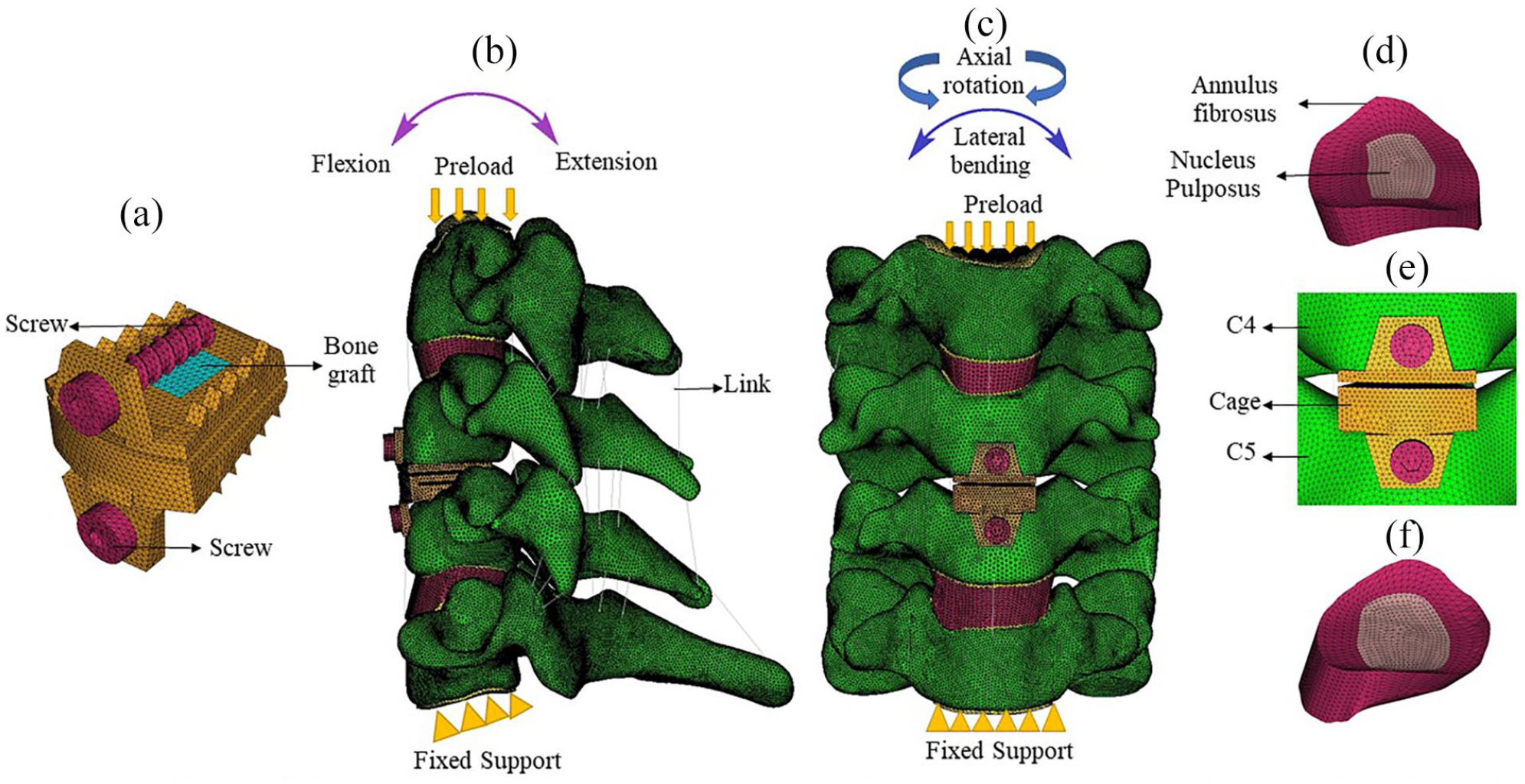
FE model of the surgical procedure: (a) S-type dynamic cage with bone graft, (b) lateral view of the model after one-level ACDF using S-type dynamic cage, (c) the frontal view of the FE model after one-level ACDF using S-type dynamic cage, (d) intact intervertebral disc C3-C4 segment of the model, (e) the S-type dynamic cage at C4-C5 segment, and (f) intact intervertebral disc C5-C6 segment.
The trapezoidal shape matches the vertebra body and increases the stability in all the physiological motion. 17 The wedge like shape in the anterior side of the design will help us to restore the natural cervical lordosis. 18 The S-type dynamic cage is designed in such a way, that the intervertebral disc height in the anterior side and the posterior side is maintained. 19 Two slits are introduced in the cage to allow the physiological motion. The transferring of the load in the anterior cervical column is maintained by the slit. In order to avoid migration and subsidence of the cage the teeth’s are provided in the superior surface and the inferior surface of the of the cage. The central cavity provided in the cage need to be provided with a good osteoinductive materials. 17 In order to provide bone fusion between the adjacent vertebra a square window of 5 mm is provided in the center of the cage. 20 The cage model was virtually inserted in to the C4-C5 level after the removal of the intervertebral disc, and the anterior longitudinal ligament.
Finite element model development
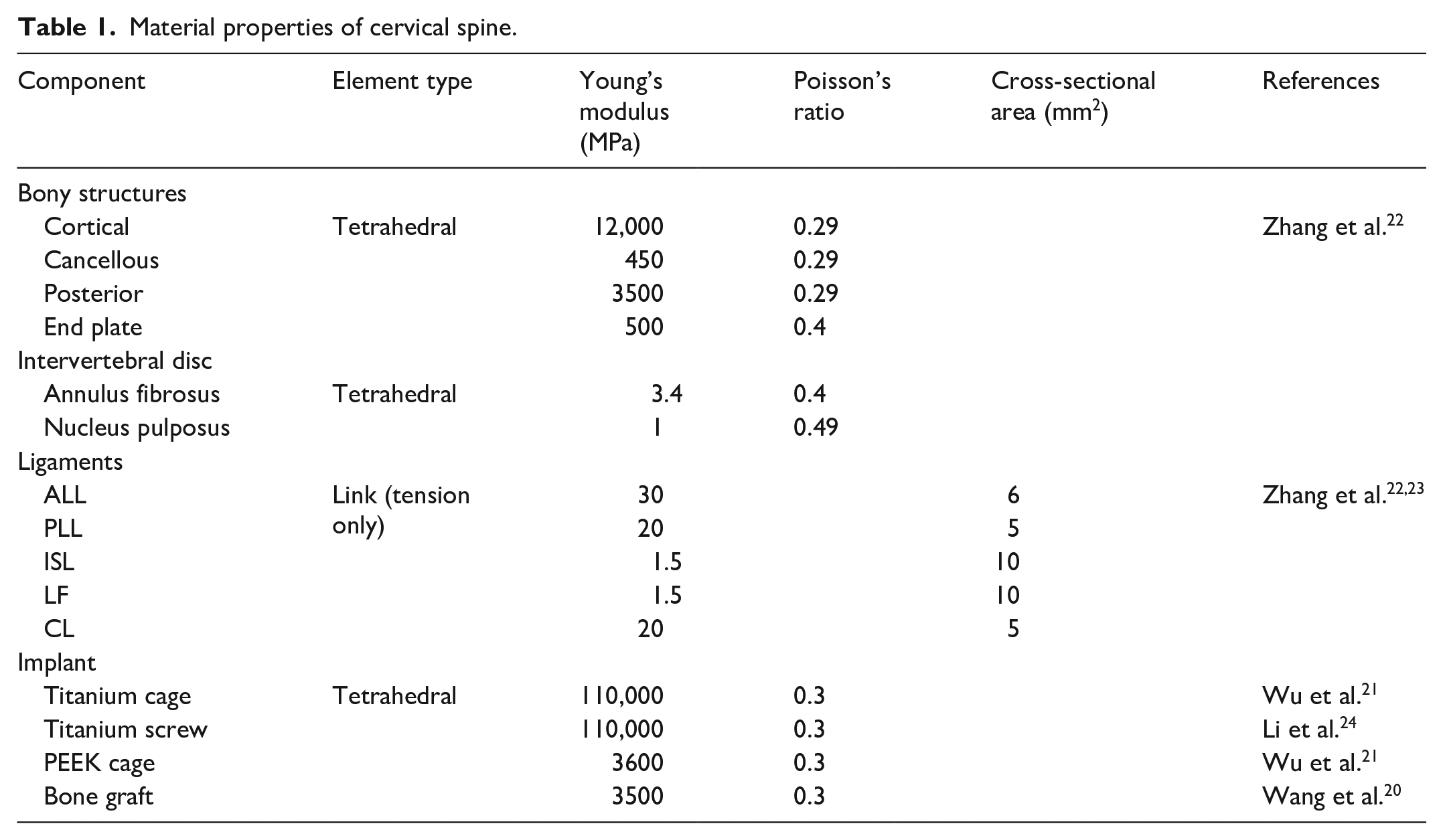
The meshing was created using HyperMesh software and imported in to ANSYS 18.2 for post processing as shown in shown in the Figure 1. The vertebra and the intervertebral disc and cage were modeled using first order solid tetrahedral elements. The interaction between cage and the vertebra was set to frictional surface to surface contact. The coefficient of friction between the vertebrae is 0.3. 21 The interaction between the bone graft and the cage is defined as surface-to-surface contact. The coefficient of friction between the vertebrae and cage is 0.07. 20 The ligaments used in this study are anterior longitudinal ligament (ALL) the capsular ligament (CL), the posterior longitudinal ligament (PLL), the ligamentum flavum (LF), and the interspinous ligament (ISL). The ligaments were modeled using tension only link elements. The material properties of the finite element model were given in Table 1.20–24 After the convergence test was conducted, we found 0.5 mm is optimum size for the element. 25 The percentage of accuracy of the convergence test is 3% for the finite element model. 25 To simulate the head weight 50 N of compressive force is applied as a preload at the superior endplate of the C3 vertebra.26,27 A moment of 1 Nm is applied in all physiological motion.26–28 In all the loading protocols the inferior endplate of C6 level motion was fully constrained.
Material properties of cervical spine.
Results
Range of motion at the adjacent segment for Ti and PEEK cages
In all the physiological motion both titanium and PEEK cage shows a reduced motion in the adjacent level when compared with the intact finite element model. In titanium cage for 0.5 Nm load the C5-C6 level exhibits reduced motion around 8% in extension and in the left axial rotation the highest value is observed in the C5-C6 level and it is around 20%. In PEEK cage in the C3-C4 level reduced motion of 2.8% observed in flexion and in C5-C6 level we found 12% is the higher motion observed in extension. In Titanium cage for 1 Nm load the C5-C6 level exhibits reduced motion of 4% in left lateral bending and in the right axial rotation in the C3-C4 level the highest value is 12.5%. In PEEK cage in the C3-C4 level reduced motion of 1.6% observed in flexion and in C5-C6 level we found 12% is the higher motion observed in left lateral bending. In titanium cage for 1.5 Nm load the C5-C6 level exhibits a reduced motion around 3.6% in flexion and highest motion is observed in C3-C4 level around 13% for right axial rotation. In PEEK cage in the C5-C6 level reduced motion of 1.8% observed in flexion and in C3-C4 level we found 8.7% is the higher motion observed in right axial rotation. In titanium cage for 2 Nm load the C5-C6 level exhibits a reduced motion of 4.6% in extension and highest value is observed in C3-C4 level around 11.6% for left lateral bending. In PEEK cage in the C5-C6 level reduced motion of 1.5% observed in extension and 4.8% is the higher motion observed in flexion. The range of motion for flexion and extension is shown Figure 2(a) for lateral bending left and right is shown in Figure 2(b) and axial rotation left and right in Figure 2(c). The percentage of changes in range of motion of the adjacent segment are summarized in Table 2 for Titanium cage and PEEK cage.
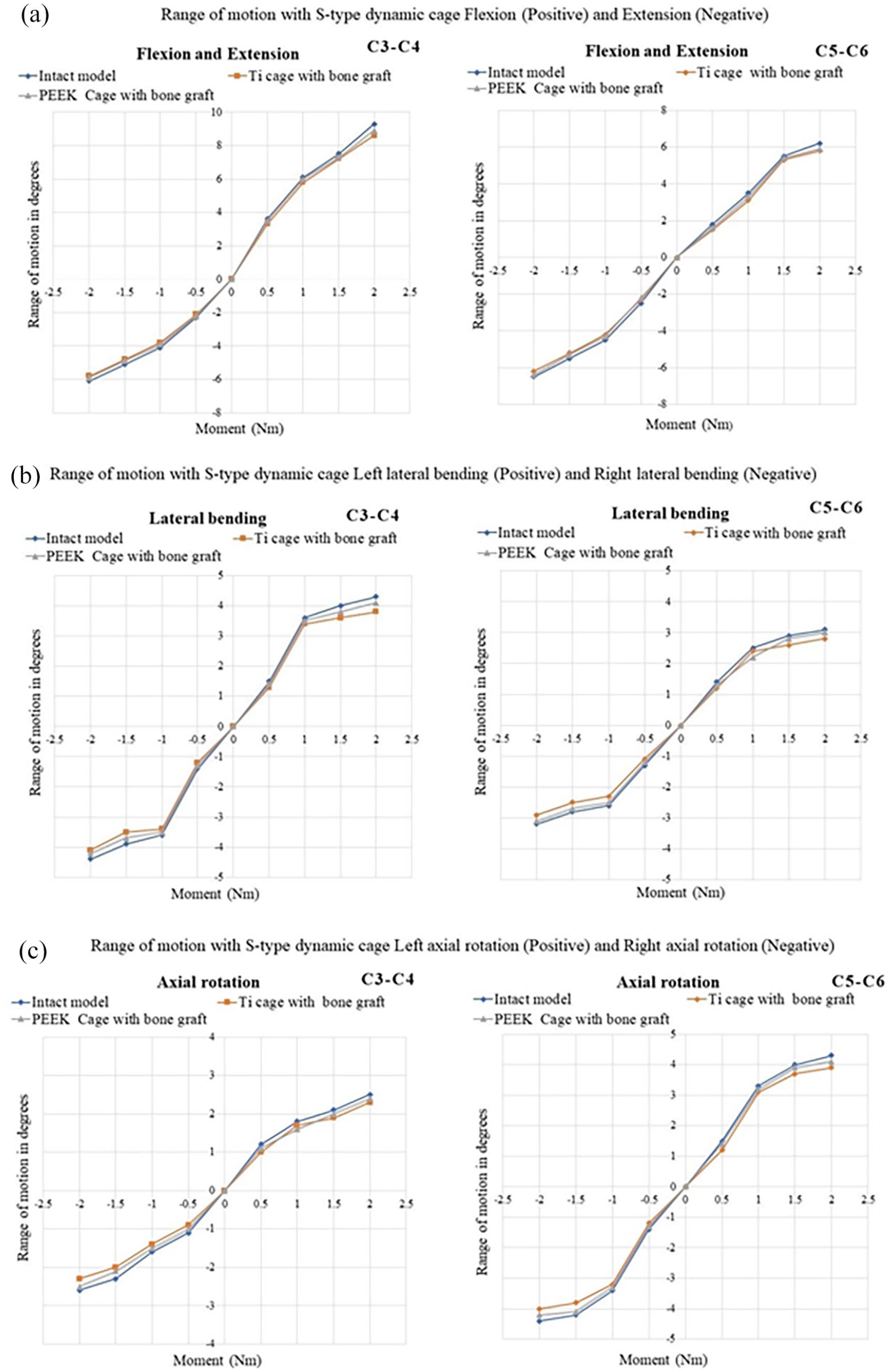
(a) Summary of range of motion flexion and extension, (b) summary of range of motion lateral bending left and right, and (c) summary of range of motion axial rotation left and right.
Percentage of reduction in range of motion for titanium and PEEK cage.
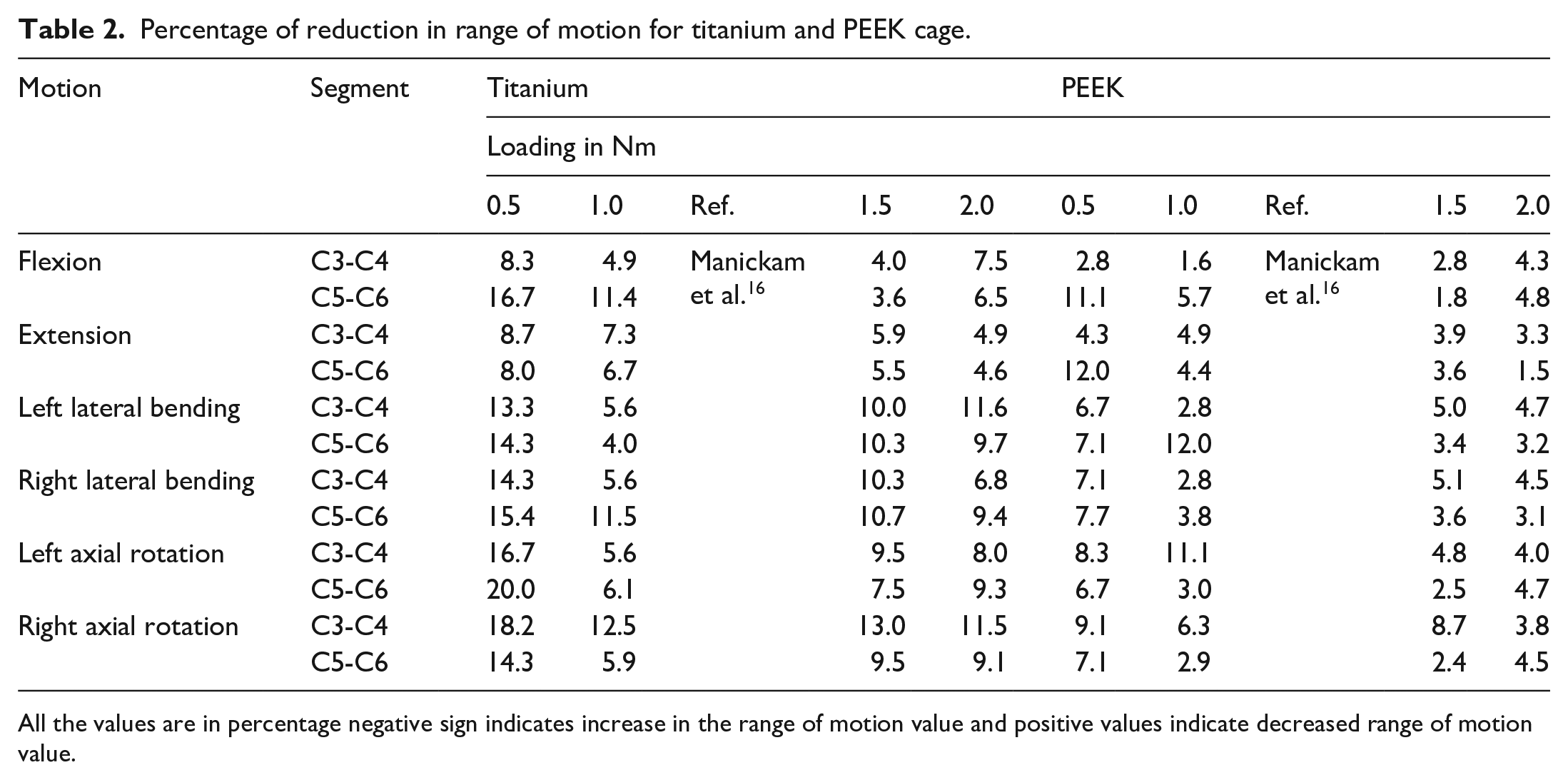
All the values are in percentage negative sign indicates increase in the range of motion value and positive values indicate decreased range of motion value.
Intradiscal stress at adjacent segment
The adjacent side intervertebral disc stresses for titanium cage is shown in Figure 3 and for PEEK cage in Figure 4. The adjacent side intervertebral disc stresses were compared with the intact model for load variation and summarized in Table 3. In flexion for 0.5 Nm in the C5-C6 level 4.2% of stress value is slightly higher and in the left and right lateral bending the disc stress values were higher by 2.2%–71.2% when compared with the intact healthy finite element model. In the remaining levels in all the motion the disc stress was reduced by 1.6%–44.9% from this we can find the adjacent level disc stress are reduced even if the loads are varied.
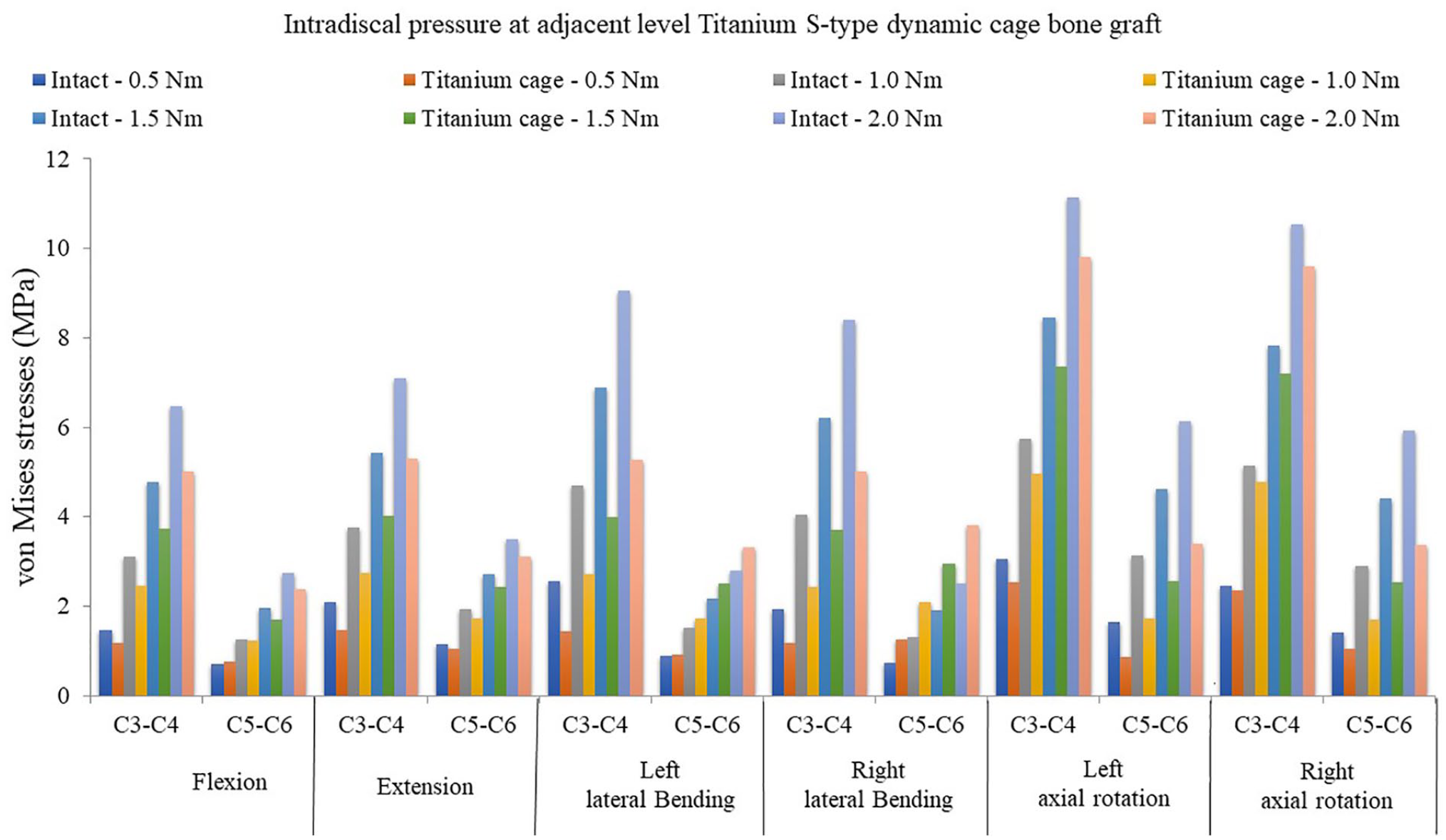
Adjacent disc stress with S-type titanium dynamic cage.
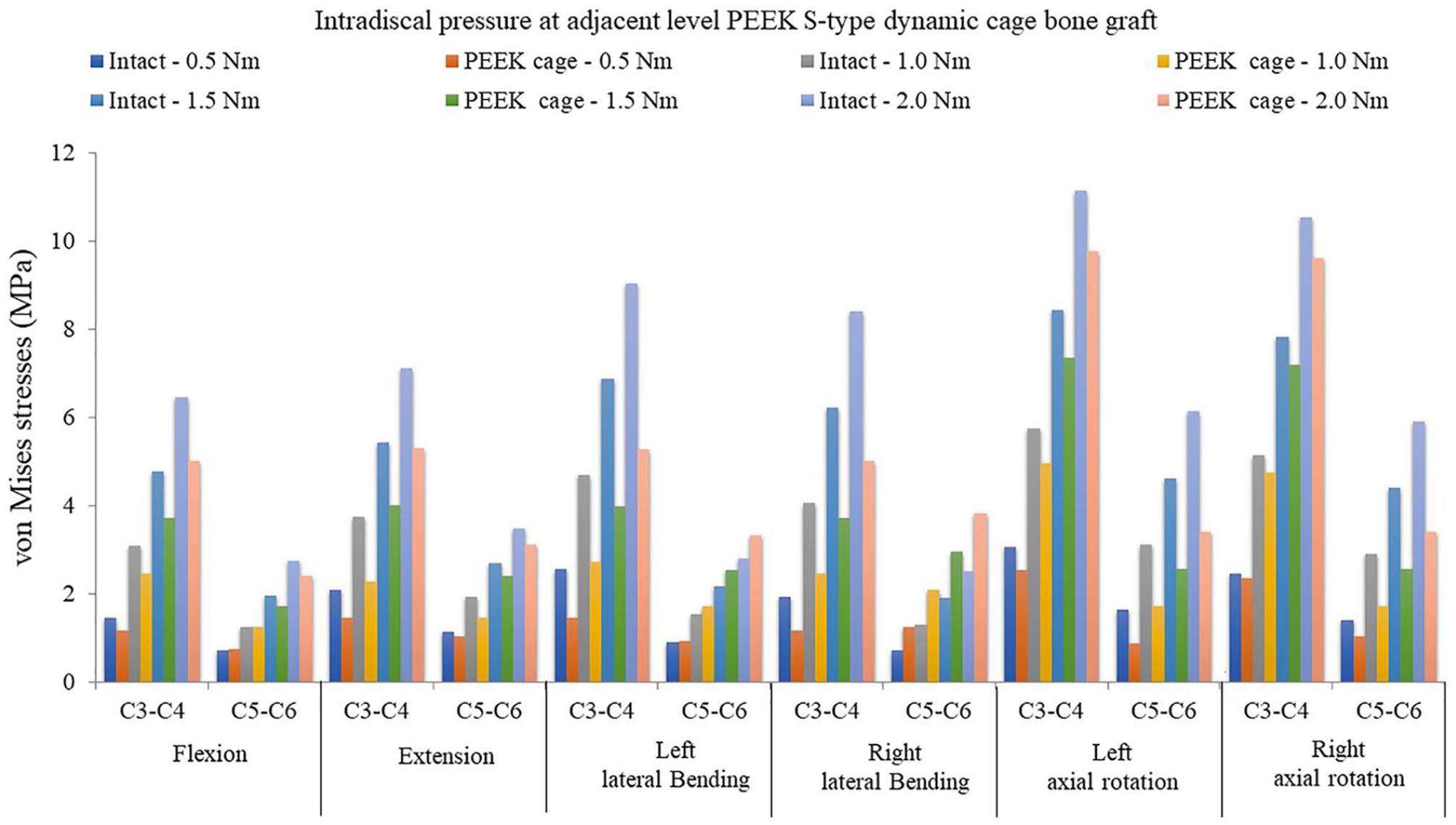
Adjacent disc stress with S-type PEEK dynamic cage.
Percentage of changes in the intradiscal stress at adjacent segment in titanium and PEEK cage.
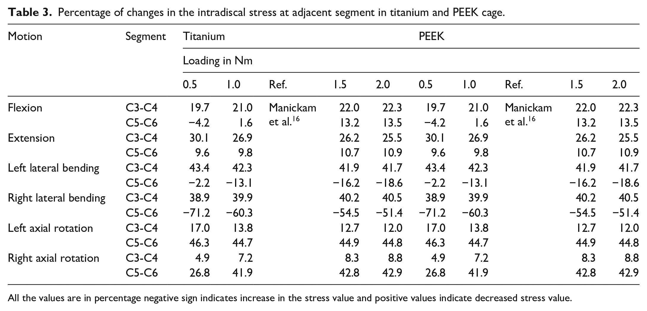
All the values are in percentage negative sign indicates increase in the stress value and positive values indicate decreased stress value.
Discussion
The adjacent segment degeneration is still under debate either it is a consequence of natural degenerative process or because of cervical fusion. 29 The intradiscal stress in the adjacent segments is a very important factor which develops adjacent segment degeneration. 30 According to 31 it will take 6–12 months to occur fusion between the adjacent vertebra after discectomy. In the in vitro studies they demonstrated that intradiscal stress was increased at the adjacent level after ACDF surgery. 32 The stiffness of the cage and the match between the cage and the endplate are the major factors need to considered because these parameters play a major role in case of adjacent level disc degeneration. 33 Biswas et al. 34 reported that after implantation of single level artificial disc replacement ADR maintains the range of motion closer to natural model and it concludes a low change of disc degeneration after the implant. Rana et al. 35 studied posterior dynamic stabilization with flexible rod device and found it is more effective for fusion and maintains the range of motion.
Our major hypothesis is reducing the adjacent disc stress by providing a S-type dynamic cage it is possible to help the cervical spine in maintaining the load in the cervical column, range of motion and reduce the stress in the adjacent level. So, in our study we designed a S type dynamic cage with bone graft in the fusion level to maintain the range of motion in the adjacent level and reduce the adjacent segment disc stresses. The dynamic cage in the fusion level provides mobility so the fused vertebrae segment will not affect the adjacent segment. In general, the fused surgical segment vertebrae will fuse together and forms as single unit. So, this fused vertebra will make hypermobility in the adjacent segments so due to hypermobility the adjacent side disc stress will be accelerated and it will result in adjacent segment disc degeneration. Now by providing the motion in the fusion level the adjacent segment degeneration is prevented. In our study we found the motion and the intervertebral disc stress is maintained in the adjacent segments of the fusion level and we varied the load till 2 Nm and in that also S-type dynamic cage is capable of maintaining the motion and the intradiscal pressure in the post-surgery.
The FE model without muscles structure could not replicate the natural phenomenon of the cervical spine. The clinical outcomes of the following S-type cage may be different from the results achieved from finite element model because of the loading conditions, material properties and location of the implants. The material properties assigned in our FE model is linear elastic, homogenous and isotropic. The focus of our study is majorly concentrated on the design of the cage. Finally, our finite element simulation study should be validated with the in vitro study if possible.
Conclusion
Within the limitation of our study, it can be concluded that in the S-type dynamic cage for both titanium and PEEK the range of motion is maintained in the adjacent segment in all the physiological motion and the stress in the adjacent segments were reduced when comparison with the intact model. Further investigations and clinical studies are required whether the S-type dynamic cage would be useful for cervical fusion.
Footnotes
Declaration of conflicting interests
The author(s) declared no potential conflicts of interest with respect to the research, authorship, and/or publication of this article.
Funding
The author(s) received no financial support for the research, authorship, and/or publication of this article.