
Abstract
Purpose:
To evaluate the biomechanics effect of modified cortical bone screw technique (MCBT) with other traditional internal fixation systems on lumbar osteoporotic wet specimen.
Methods:
Four different finite element models were established using CT data: (1) lumbar osteoporosis model without internal fixation system; (2) traditional pedicle screw technology (TT) model; (3) traditional cortical bone screw technology (CBT) model; (4) MCBT model. The changes of global displacement, intervertebral disc displacement of all models and internal fixation system Von Mises stress among the three models were compared under the same physiological load.
Results:
Compared with the other three models, the total displacement of the modified CBT screw model was the smallest, with the maximum displacement of 0.216 mm; The intervertebral disc displacement of the modified CBT screw model was the smallest, with the maximum displacement of 0.149 mm; the internal fixation system Von Mises stress of the modified CBT screw technique model was the largest compared with the other three models, The maximum Von Mises stress is 232.73 MPa.
Conclusion:
Compared to traditional pedicle screw and traditional CBT, MCBT has better mechanical stability, and it is of certain clinical application value.
Keywords
Introduction
Over the past few decades, spinal internal fixation system, especially pedicle screw technology, plays an important role in lumbar spine surgery.1,2 However, Cortical bone trajectory (CBT) is a novel lumber screw internal fixation technology, which was proposed by Santoni in 2009. 3 Compared with the traditional pedicle screw, which were inserted along the anatomical axis of the pedicle, CBT can reduce the scope of surgical exposure and fusion level as well as the damage to the paravertebral muscle and soft tissue.4–7 CBT has good internal fixation effect with a 30% increase in uniaxial yield pull-out load and 1.7 times holding force compared with the traditional pedicle screw.8–11 Sansur et al. 12 evaluated that the biomechanical effect of lumbar cortical bone and believed that CBT pedicle screw could significantly increase the average load of screws, providing a viable alternative for traditional screw fixation. Matsukawa et al. inserted screws of the same shape and size into the same pedicle, compared the trajectories of the screws entering the pedicle in five different directions in 20 vertebra L4, and analyzed the data using nonlinear finite element analysis. He found that the regional difference in vertebral bone density and the densification of bone screw interface were the reasons for the difference in stiffness between different screw tracks.13,14
However, our previous studies5,15 found traditional CBT screw anatomical reference cannot play a role in spinal revision surgery. The 3D printed guide plates designed based on classic anatomical references also cannot accurately conform to the bone surface during spinal revision surgery and then lose the ability to guide, so the screw point and angle can only be confirmed by frequency X-ray. Another point that it is difficult to apply traditional CBT to achieve solid fixation in pedicle screw revision operation. Because the traditional CBT technology failed to utilize the marginal cortex at the screw starting point, the inner wall of the pedicle and the lateral side of vertebral endplates.5,15 Through further studies on the anatomy and image measurement of lumbar isthmus screw parameters, the traditional CBT was improved on insertion point and angle for screw placement, which was called modified CBT technology.5,15 Currently, the research on MCBT technology is mainly in the field of anatomy and imaging, whereas the research on biomechanics is relatively few. In the paper, the stability of MCBT and the other different internal fixation system of the human lumbar spine under physiological loads was studied. The mechanism of MCBT insertion technique in patients with lumbar degenerative disease was further studied.
Materials and methods
Image data and modeling
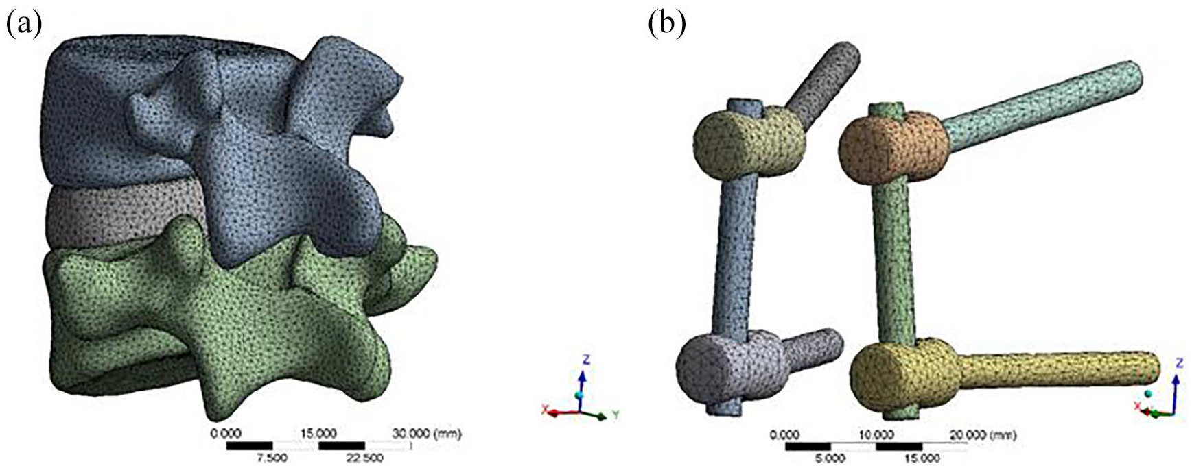
Images of human lumbar vertebrae were captured by the department of PET/CT, the First Affiliated Hospital of Xinjiang Medical University. In this study, a female wet specimen with lumbar osteoporosis was selected. Here, Bone mineral density (BMD) in vertebra L4 was 0.540 g/cm, and T score was −3.4. A 64-slice spiral CT (PHILIPS Company, The Netherlands) was used to perform a computed tomography scan of the vertebral body with a slide of 0.25 mm. The obtained CT data were imported into the mimics 19.0 (Materialize, Leuven, Belgium) for medical modeling to establish the coating. Select the area where the model is to be established, eliminate the remaining areas, determine the mask gray value of the selected area, the gray range is 226–2142, and calculate and generate the L4–L5 lumbar spine to be retained. Cortical bone, cancellous bone, upper and lower endplates, annulus fibrosus, and nucleus pulposus were constructed to complete vertebral division (Figure 1(a)) and intervertebral disc formation (Figure 1(b)).Among them, nucleus pulposus accounted for 46% of lumbar intervertebral disc, annulus fibrosus accounted for 54%, each vertebra was meshed with four-node solid elements, representing the trabecular bone enveloped by a layer of cortical bone with changing thickness in five regions: endplates and anterior walls of the vertebral body (0.4 mm), upper pedicle (2 mm), lower pedicle (1.87 mm), posterior processes (1 mm), and insertion area of pedicle screws (0.8 mm).4,16,17
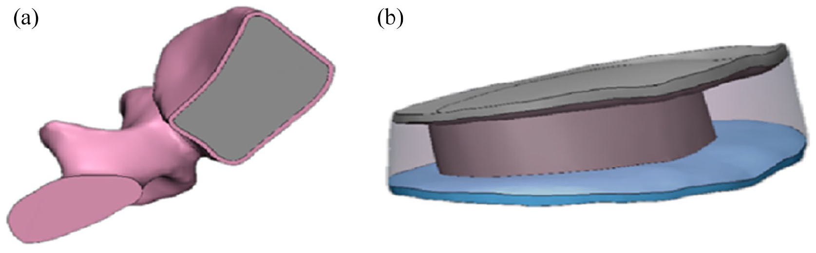
(a) Vertebral partition model and (b) intervertebral disc model.
Screw placement in MCBT model
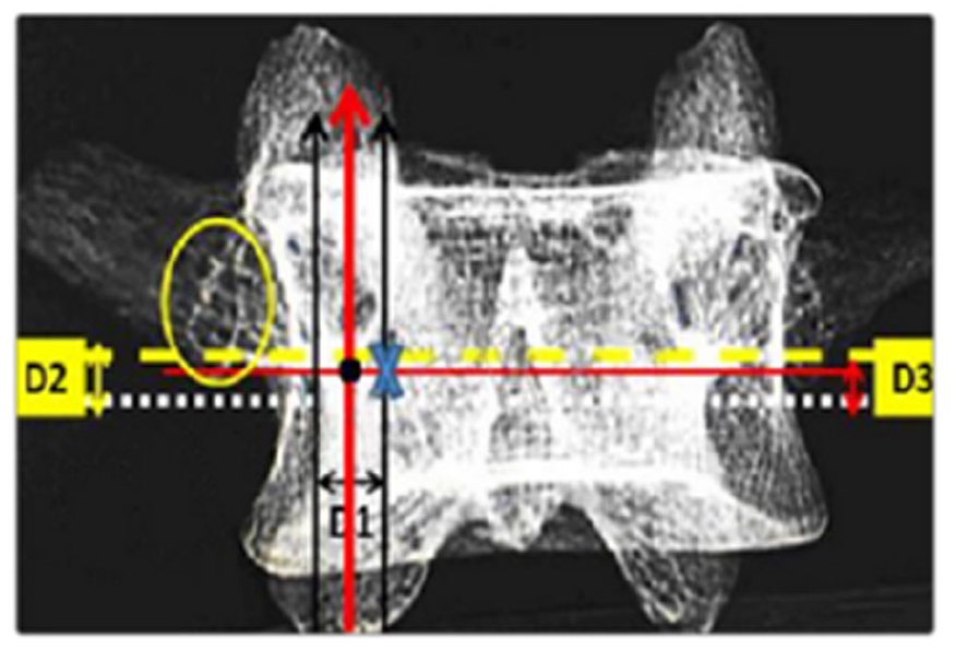
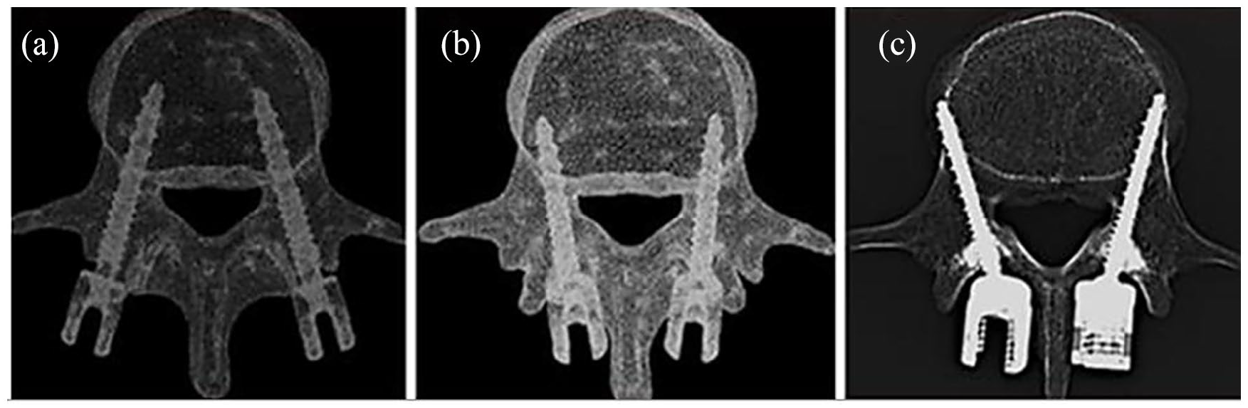
In traditional CBT technology, the vertical axis was perpendicular to the center of the superior articular process, while the horizontal axis was the line 1mm below the transverse process. 18 The screw was inserted into the junction of vertical axis and horizontal axis with an extroversion angle of 10°and a cephalic tilt angle of 25°. The modified methods we used in the present series was as described in previous studies.5,15 D1 was the distance between the tangent of the medial wall of vertebral arches and the lateral margin of the isthmus. D2 was the distance from the tangent of the lateral isthmus on both sides to the inferior border of the transverse process. D3 was obtained by lowering 1 mm from D2. The coordinate origin was the isthmus tangent point. The starting point of modified CBT (blue “x” in Figure 2) was defined by moving the distance of D1 value to vertebral midline horizontally and then the distance of D3 value straight up (Figure 2). Compared with the CBT, in MCBT, the insertion point was moved inward by 2–3 mm, with the head tilt angle of 30° and the extroversion angle from10° at upper lumbar (L1\L2) to 22° at lower lumbar spine (L5). As shown in Figure 3, the nail placement trajectories of the three models are shown:
Model assembly and grid division
Universal screw was designed in the 3D model building software (SolidWorks15.0) and 3D image generation and processing software was imported in STL format. By using Roy-Camille technique, traditional CBT technique as well as MCBT technique, different screw tracks were made and assembled with universal screw by Boolean subtraction operation. Before assembly, the model can be meshed separately, as shown in Figures 4 and 5. The vertebral body model is divided by three-dimensional tetrahedral elements. The number of cortical bone units is 68,215, solid187, the number of cancellous bone units is 117,132, the number of upper and lower endplate units is 11,358, the number of annulus fibrosus units is 9563, and the number of nucleus pulposus units is 12,825. The model analysis was carried out using finite element software.
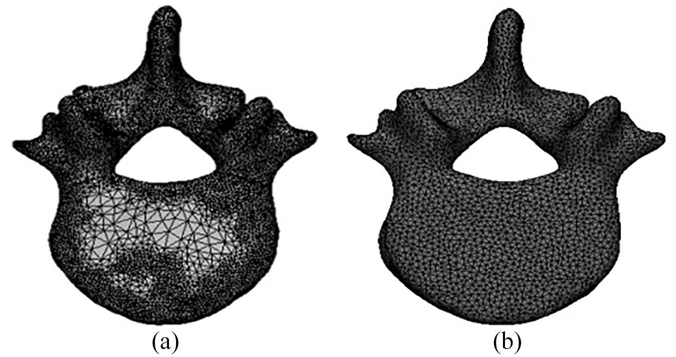
Optimization of mesh generation of vertebral cortical bone: a: before mesh optimization; b: After grid optimization.
(a) Mesh division of lumbar model and (b) mesh division of internal fixation system.
Material properties
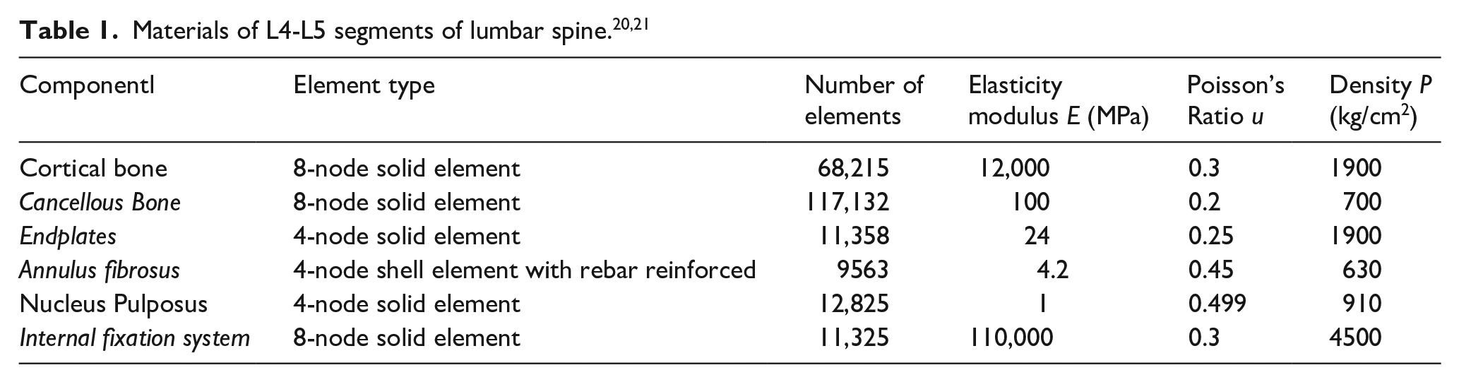
In order to simplify the calculation of the model, the model material can be divided according to the CT value. At the same time, due to the weak anisotropy of the bone, the lumbar spine can be equivalent to a homogeneous isotropic material under the same elastic modulus in the lumbar spine (Table 1).
Setting of boundary conditions and constraints
Four models were used to mimic the upright standing of the human body, A load of 500 N (about two-thirds of the body weight) was applied to the upper surface of vertebra L4 The lower surface of vertebra L5 was set as a completely fixed constraint, with no displacement and rotation when the force was applied. Notably, the insertion point and articular process were very close in traditional pedicle screw model and the traditional CBT screw model, which damaged the joints and then led to the acceleration of joint degeneration. In addition, contact of facet joints after screw placement limited the movement, so the contact surface of upper and lower facet joints should be set as binding contact, in order to over Von Mises stress the intervertebral disc in the adjacent intervertebral disc and then cause degeneration of the adjacent intervertebral disc easily. However, the entry points of MCBT technology were far away from articular process and even the end of screw cannot touch it either, which reduced the damage mentioned above. After the screw and model were assembled, the contact was set as binding contact. The contact between the upper as well as lower endplates of the disc and the lower surface of L4 as well as the upper surface of L5 was set as binding contact. It is frictional between the upper and lower articular processes. The friction coefficient was set as 0.2 (Figure 6). 22
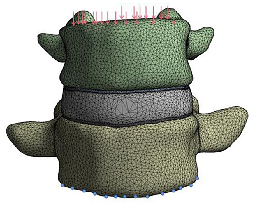
Boundary conditions of finite element calculation model.
Discussion
Model axial displacement verification
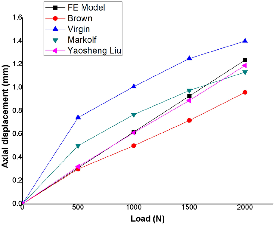
In order to describe the mechanical properties of the lumbar spine under three nail placement methods, the maximum Mises Von Mises stress and maximum axial displacement were used to evaluate the strength of the whole lumbar spine. Under the same load, the smaller the maximum axial displacement of the lumbar spine, the stronger the bearing capacity of the lumbar spine. In numerical simulation, in order to ensure the accuracy of the model, it is necessary to verify the finite element model, and the verification method depends on its research purpose. According to Yogananda, 23 the most effective method to verify the finite element model is to combine the load displacement curve with the dynamic response test of the local structure. In this study, the lumbar axial compression force was taken as the research object, and the axial displacement of the model was calculated, and compared with the in vitro experimental results of Brown, 24 Markolf, 25 Virgin 26 and the simulation results of Yaosheng Liu, 27 the reliability of the model was verified. As shown in the figure, under the pressure distribution of 500, 1000, 1500, and 2000 N, the axial displacement of the model is 0.304, 0.62, 0.93, and 1.24 mm, respectively. The results of finite element analysis in the load displacement curve are between the experimental results in vitro in the literature, and are similar to Yaosheng Liu’s simulation curve.
Von Mises stress comparison of four models
In this study, four models were included: unnailed model (Figure8(a)), traditional pedicle trajectory model (Figure 8(b)), CBT model (Figure 8(c)) and MCBT model (Figure 8(d)). The Von Mises stress and displacement of the four models were compared and analyzed under the same physiological loads.
As demonstrated in Figures 7 and 8, the model can be divided into two stages for analysis before and after screw placement. Maximum Von Mises stress was 102.12 MPa in traditional pedicle trajectory model compared with the maximum Von Mises stress of 23.08 MPa in unnailed model (Table 2). The difference of these two models was 79.04 MPa. The Von Mises stress of traditional pedicle trajectory model, CBT model and MCBT model were 102.12, 162.5, and 232.73 MPa, respectively (Table 2). The differences among these three models were 60.38 and 70.23 MPa, respectively. In the simulated physiologic upright posture of human body, the lumbar spine was fully loaded in the unnailed model, while the loads were at the internal fixation system after screw placement, which ensured the stability of lumber spine in patients. Therefore, internal fixation system may have a protective effect on the pathologic lumbar vertebrae or corresponding operations section.
Comparison of simulation data and experimental data.
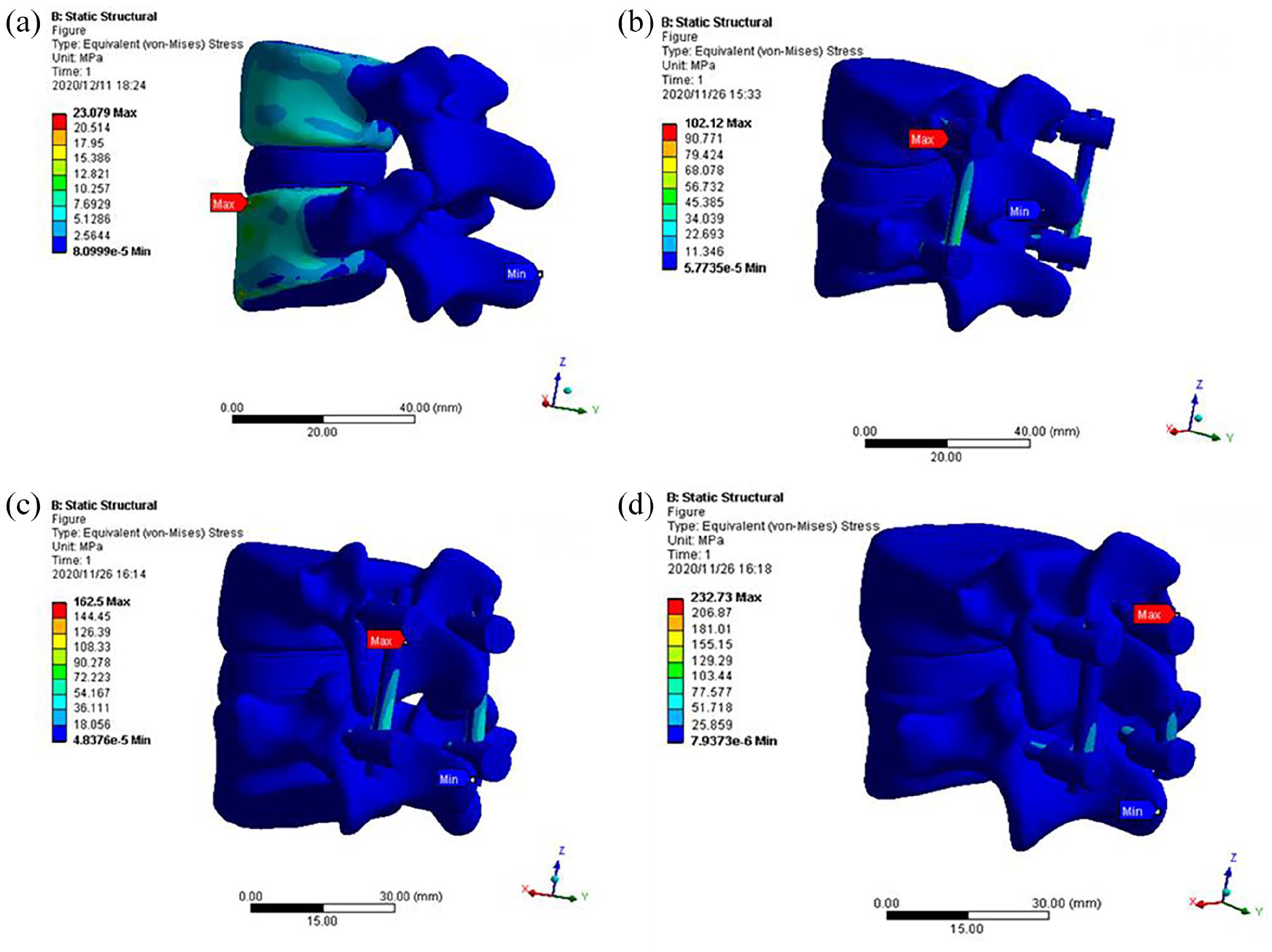
(a) Von Mises stress distribution of Unnailed model, (b) Von Mises stress distribution of the traditional pedicle screw model, (c) Von Mises stress distribution of cortical bone trajectory (CBT) model, and (d) Von Mises stress distribution in a modified cortical bone.
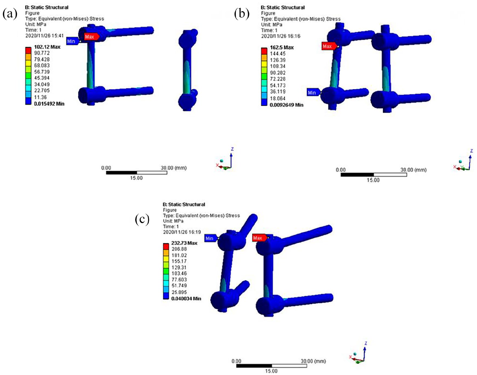
The maximum Von Mises stress of different models under the same load.
The Von Mises stress differences among the three models with screw insertion were caused by the different cortical bone density in the trajectory. Compared with the traditional pedicle trajectory model, CBT model and MCBT model increased the contact surface between the screw and vertebral cortical bone, and reduced the contact surface with cancellous bone in the trajectory. Previous evidence demonstrated that the regional difference of vertebral bone density and the densification of bone screw interface were responsible for the differences in stiffness among different screw trajectories.13,14
Among these three screw placement models, we found that with the growing increase of the contact surface between the screw and the cortical bone in the trajectory, the holding force of the internal fixation system gradually strengthened, the internal stability of the internal fixation system gradually increased and the Von Mises stress on the internal fixation system was increasingly strengthened, making the MCBT model larger than the traditional CBT model and larger than the traditional pedicle model. Thus, MCBT model was the optimal model for screw insertion, especially in patients with osteoporosis.
Displacement distributions of four models
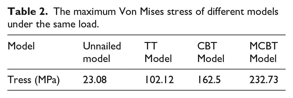
As presented in Figure 9, the four models were compared before and after screw placement under the same loads. the maximal displacement was 0.304 mm in unnailed model, while the maximal displacement in traditional pedicle trajectory model was 0.272 mm. The displacement of traditional pedicle trajectory model was 0.032 mm smaller than that of the unnailed model, which was mainly responsible for the internal fixation and Von Mises stress distributed on the screw. The displacement of traditional pedicle trajectory model, CBT model and MCBT model were 0.272, 0.237, and 0.216 mm, respectively. The displacement differences among the three models were directly related to the screw tracks. After improving the trajectory and internal fixation, the effective contact surface between the cortical bone and screw increased, and therefore the displacement decreased. What’s more, the displacement of intervertebral disc was decreased. The displacement of intervertebral disc in unnailed model, traditional pedicle trajectory model, CBT model and MCBT model was 0.249, 0.187 mm, 0.164 mm and 0.149 mm, respectively. Accumulated evidence has shown that the intervertebral disc serves as cushion between the adjacent vertebrae, allowing it to deform and return under various loads.28,29 The nucleus pulposus is the conduction body of intervertebral disc, and it has been found that the pressure in nucleus pulposus is directly related to the axial loading.30,31 Therefore, the displacement of the intervertebral disc in the four models decreased successively after screw placement.
(a) Displacement distribution of the model of lumbar spine without screw, (b) displacement distribution of traditional pedicle trajectory model, (c) displacement distribution of cortical bone trajectory model, and (d) displacement distribution in a modified cortical bone trajectory model.
Effectiveness of internal fixation system
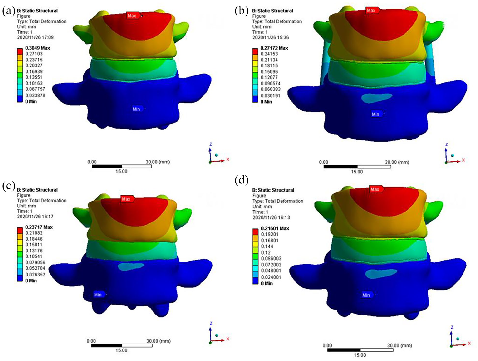
After screw placement, the pressure of L4–L5 lumbar segments will be borne by the internal fixation system. However, since L4 and L5 vertebral bodies are nailed and connected with each other, the maximum Von Mises stress will appear at the ball and socket structure. 32 Herein, these results hinted that maximize Von Mises stress on the screw was at the ball and socket structure, secondary to the location of the link rod Von Mises stress (Figure 10(a)). We found that lumber spine in CBT model especially MCBT could bear the largest external force under physiological loads, which decreased internal pressure during the degeneration of intervertebral disc under load and protected nucleus pulposus from herniation (Figure 10(B)). Thus, CBT model may have good biomechanics effect on intervertebral disc degeneration in patients. Traditional pedicle trajectory technology and traditional CBT technology are currently commonly used internal fixation methods for lumbar osteoporosis, intervertebral disc herniation and other diseases in clinical,3,33–36 Importantly, MCBT technology improved the insertion point and angle compared with traditional pedicle trajectory and traditional CBT. MCBT technology avoided the screw surface fracture in the process of insertion and collision with joint, and enhanced the holding force of internal fixation system and the stability of fixation system (Figure 10(c)). In summary, MCBT technique was the most effective method for the internal fixation of the patient’s vertebral body.
(a) Von Mises stress distribution of traditional pedicle screw fixation system, (b) Von Mises stress distribution of CBT screw internal fixation system, and (c) Von Mises stress distribution of the modified cortical screw fixation system.
Conclusion
In this study, the biomechanical properties between MCBT technology and the traditional screw placement technology was compared and analyzed using numerical simulation method. The Von Mises stress, displacement and Von Mises stress on L4–L5 segment of lumbar spine were obtained during physiologic upright posture of human body. The conclusions were as follows,
(1) The displacement in the four models decreased successively after screw placement because the effective contact surface between the cortical bone and screw increased with the improvement of the screw trajectory. (2) The displacement of intervertebral disc was also reduced due to Von Mises stress occlusion. (3) The Von Mises stress changes of the internal fixation system were as follows: There was the minimum Von Mises stress change in traditional pedicle trajectory model, while there was the maximum Von Mises stress change in MCBT model. Thus, the vertebral body’s holding force on screws was increased in MCBT model, which enhanced the stability of the internal fixation system, made it difficult to loosen or prolapse and reduced the incidence of postoperative complications in patients.
After the screw is placed in the model, due to the large difference between the young’s modulus of the screw and the lumbar material, the stress concentration will occur at the screw position under the load, resulting in the stress shielding of the model after the screw is placed. Yes, the stress borne by the lumbar spine will be reduced, and the stress concentration will occur at the screw position, which will reduce the stress and displacement of the lumbar model.37,38 MCBT technology improved the entry point according to the location of lumbar isthmus that is inherent and not susceptible to degeneration. MCBT technology provided more reasonable and practical clinical model and parameters, and eventually shortened the operation time, reduced intraoperative blood loss and injury to adjacent muscles and soft tissue.5,15 MCBT technology effectively avoided the impact and collision between the screw and the facet joint compared with traditional pedicle screw and CBT technology. However, there are still some deficiencies in this study. For example, this model does not establish the lumbar ligament, which will inevitably increase the error of simulation data. Therefore, a more perfect model should be established as far as possible in the following research. The ball and socket structure of internal fixation system is easy to break in clinic. At the same time, the simulation results of different systems show that the Von Mises stress at the ball socket joint is the largest. Although MCBT can reduce the Von Mises stress on the intervertebral disc, the Von Mises stress concentration at the ball socket structure is the most obvious. Thus, further research should improve the materials and connection modes of internal fixation system and make the MCBT technology be applied to clinical practice effectively.
Footnotes
Declaration of conflicting interests
The author(s) declared no potential conflicts of interest with respect to the research, authorship, and/or publication of this article.
Funding
The author(s) disclosed receipt of the following financial support for the research, authorship, and/or publication of this article: This study was supported by National Natural Science Foundation of China (NSFC) (Grant No.: 81960415).