
Abstract
Rehabilitation exoskeletons is still an important issue to improve walking functionality and speed up treatment for patient to restore their lives faster. This paper introduces a controlled lightweight exoskeleton for lower limb rehabilitation with a friendly user interface. A model for the proposed exoskeleton design is initially developed using SolidWorks. Secondly, an optimization study is presented to minimize the total mass. Simulink model is established for the proposed exoskeleton to simulate the gait cycle. Then, a prototype is implemented using light weight material. An integrated control system based on active actuators at both hip and knee joints is presented. A simple user interface is designed to control the movements of hip and knee joints. Finally, an experimental test is performed to validate simulated data of human gait cycle for torque and angle profiles of hip and knee joints.
Introduction
Development of lower limb assist exoskeletons have been ongoing for long years for military applications and individual assistance with mobility impairments. Recovery of gait cycle is normally performed in clinics with rehabilitation equipment. Lower limb rehabilitation systems integrate many interdisciplinary areas. These systems can be attached to human limbs as wearable devices. Movement of each joint should be adjusted to perform normal human gait. Therefore, systems can drive the human limb to realize the assisted rehabilitation process. Some mechanical features were investigated to enhance the efficiency of lower limb exoskeleton. Mathematical model, virtual prototyping for exoskeleton human ankle joint was developed. Experimental tests were performed to get the pattern curve for cam mechanism design. 1 Novel 3D passive, compliant supports were connected to their respective support the knee and ankle joint assemblies to properly sense the contact forces. 2 Active power-assist lower limb was developed such that man–machine coupling points were tested at feet and torso to facilitate transferring assistive force to human body. 3 A graphical methodology was proposed to define a whole set of exoskeleton systems used for assistive purposes containing one degree of freedom (DOF) planar mechanisms with up to five angular outputs. 4
The prototype was developed and verified by testing on walking on rough ground, stair climbing, and obstacle crossing. All main tasks including object motion perception, load transmission, and movement cooperation were tested. Also, gravity was involved in exoskeleton mechanism design. A passive lower limb exoskeleton was introduced containing spring mechanisms for gravity compensation of the lower limb. 5 A pair of mating gears was presented to transform the tension load from the springs into balancing torques at the hip and knee joints to withstand the gravity effect. Whereas adjustable size of single-leg exoskeleton for children was developed using three active joints at the hip, knee, and ankle controlled by brushless DC motors and harmonic drive gears. Another model was proposed based on gravity compensator impedance controller while adynamic model was derived and validated in Sim-Scape. 6 A portable, durable, economic, and lightweight device was presented to collect lower-limb biomechanical data of the object even in indoor or outdoor environments. Goniometers, inertia sensors, and pressure sensors were attached into a flexible information collection system to get the required gait information in real-world daily-living scenarios. 7
Generally, exoskeleton systems maybe classified into three types according to power usage: passive, quasi-passive, and powered systems. Passive exoskeleton systems are used to reduce cost and weight of exoskeletons such that they are mechanical systems that do not need actuators to process. Mechanical springs are essential elements in passive exoskeletons. Exoskeletons were developed to assist knee motion by using spring-clutch mechanism 8 or by using a four-bar linkage. 9 Other exoskeletons were developed to assist ankle motion by using elastomer springs-clutch mechanism 10 or by using timing mechanism that contains ratchet, toggle spring, and pawl. 11 However, a bent-leaf-spring was used to assist hip motion. 12 Powered exoskeletons contain actuators with programmable control systems to improve the rehabilitation process. A power battery may be attached to ensue mobility without external power sources. Torque analysis for lower limb joints was conducted 13 to choose the optimum electric actuators. Linear hydraulic actuators were applied for hip, knee, and ankle joints. 14 A walking assist device was introduced with bodyweight support system to minimize the reaction load by using two actuators. 15 Pneumatic actuators were applied to control an operated cam-lock device that actuate ankle foot movement at specific times of the gait cycle. 16 Furthermore, a prototype of knee ankle-foot assist device controlled by artificial pneumatic muscles throughout human walking was presented. 17 Quasi-passive exoskeletons combine mechanical components and active actuators and sensors to control and monitor motion of exoskeletons. Some quasi-passive exoskeletons were introduced to assist hip joint motion. New control scheme based on gaussian mixture models is applied to identify the movement of quasi-passive spinal exoskeleton. 18 Wearable waist assist exoskeleton was designed with active flexion/extension on hip joints using brushless motor. 19 Unpowered mechanical structure including clutches and thigh connecting rod were used as a convenient support for workers during repetitive lifting tasks. However, for knee joints, an exoskeleton was developed using linear series elastic actuator and two load cells. 20 Many control strategies were investigated. A cable-driven actuated lower limb exoskeleton for human gait exercise was presented such that an instrument PXIe-8135 controller was applied for real time control and data acquisition of the exoskeleton using LabVIEW application. 21 A modified adaptive controller including the impedance and unloading adaptation was introduced. 22 Impedance of hip and knee joints is modified by the difference between theoretical and real trajectory. The unloading adaptation was based on the error between actual and theoretical height of the hip rotation center. Sliding mode variable structure control actuated by electro-hydraulic servo system was adopted for a better dynamic performance. 23 Adaptive fuzzy logic controller based on disturbance observer and pneumatic muscle actuators were developed for wearable ankle rehabilitation robot. 24 Assistive dSPACE 1103 controller was applied for ALEX II gait trainer 25 to minimize the muscle effort compared to free walking. Exoskeleton model simulation is usually applied to verify theoretical dynamic and motion analysis, which may lead to some design modifications.
Control simulation is also applied to demonstrate and test control strategy. Modal analysis of lower limb rehabilitation exoskeleton using a 3D CAD model was developed. 26 A full leg exoskeleton was simulated into MSC.ADAMS environment. 27 MATLAB/Simulink software environment was involved in exoskeleton model simulation, analysis, and control testing. Performance of system dynamic in classical PID control, sliding mode controller, and improved sliding mode controller were compared. 28 Where, a virtual block diagram of system control technique is performed to test the feasibility of the control method. 29 SolidWorks software was applied to create a 3D dynamic model for lower limb exoskeleton. Then, model analysis was performed using MATLAB/Sim-Mechanics environment.30,31 A four-bar linkage was developed as a passive lower body mechanism by modeling the gait cycle in CAD application. Then, PD and PID controllers were simulated using Sim-Mechanics. 32 However, Sim-Mechanics was applied to create a model of a five- link biped exoskeleton robot. 33 A PID controller was included as well. Also, a humanoid robot simulation platform was introduced using Virtual Reality Modeling and Sim-Mechanics. 34
From the above literature, improvement and research on rehabilitation systems for lower limb need continuous investigation. Lightweight is a big issue that should be considered. Also, complexity of exoskeleton structure and control are still challenges. This work aims to restore human lower limbs mobility by providing support and assistance for hip and knee joints. However, lightweight, smart control, and simple user interface are main features for the proposed double-leg exoskeleton (DLEX) design. Paper is organized as follows: Section 2 illustrates basics of gait cycle. In Section 3, a design methodology of proposed DLEX is introduced. Control algorithm is discussed in Section 4. In Section 5, results of simulated model and implemented prototype are presented and discussed. Finally, Section 6 summarizes the conclusions of this work.
Basics of gait cycle
The gait cycle defines the movement of lower body joints. Generally, there are two phases: stance phase and swing phase from initial placement of the supporting heel on the ground level to the same heel contacting the ground level for the next step as illustrated in Figure 1. 35
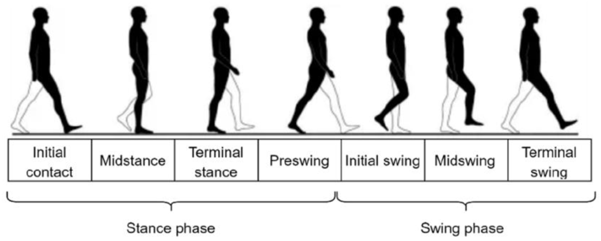
Human walking gait cycle. Reproduced unchanged from Talaa et al. 35
Gait cycle variables can be classified into four categories: space-time, kinematic, dynamic, and biologic. Degrees of freedom of lower limbs are distributed in hip, knee, and ankle joints. Walking gait considers changes in joint force, torque, and angle. Motion ranges of lower limb joints that will be considered for design of DLEX are illustrated in Table 1.
Motion range of lower limb joints for DLEX design.
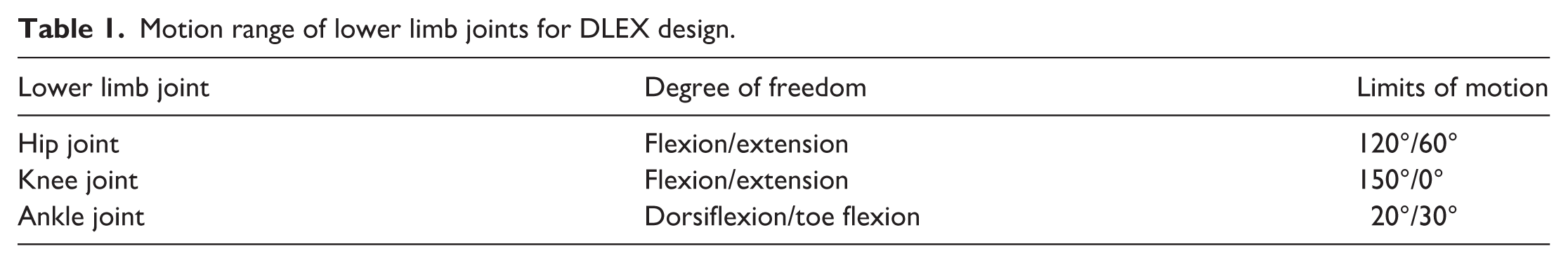
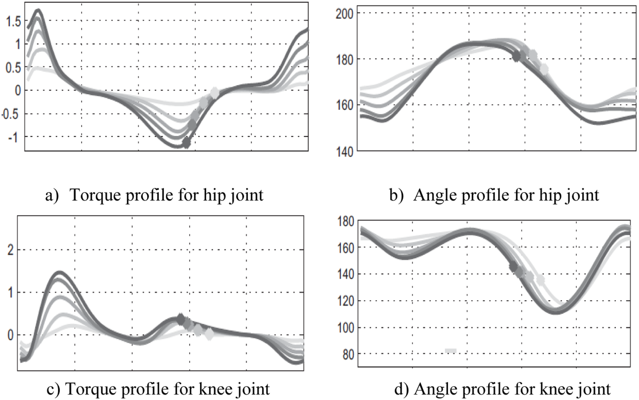
For design a lower limb exoskeleton system, the flexion/extension movement of each joint is usually the main objective. Movement limit of the corresponding DOF should be greater than the movement range of that joint. During gait cycle Figure 2 illustrates how the torque and angle profiles changes over time as a person walks for hip and knee joints. 36 That may help to analyze the kinematics and dynamics of gait, as well as to identify any abnormalities from normal gait patterns Positive values define ankle dorsiflexion, knee flexion, and hip flexion.
Design methodology of proposed DLEX
Design of a lower limb exoskeleton is an integrated process that utilizes the principles of biomechanics, robotics, materials science, simulation, and control. The Mechanical design process involves deep consideration of human biomechanics, material selection, design optimization, actuation mechanisms, and ergonomic factors to create a functional and user-friendly device.
Mechanical design and modeling of DLEX
Mechanical design of DLEX for lower limb is conducted using SolidWorks. An appropriate design of rehabilitation devices should have some features that conform human compatibility to lower cost. Proposed exoskeleton design is made of lightweight aluminum tubes AL 1060 to make the initial overall weight of the DLEX to 5.95 kg. Aluminum tubes have an excellent strength-to-weight ratio and high tensile strength to provide better structural support. The structure is designed to allow adjustments of links to match different human body constitutions. Inner and outer tubes are attached to enable easy adjustment of desired length by a movable pin. Wearability is achieved by wearable connection to realize force transmission through exoskeleton structure to human joints. Generally, the structural design of DLEX aims to improve the overall functionality of the wearable device. Design parameters including materials, dimensions, and cross sections ensure device’s stability, load-bearing capability, and the overall enhancement of rehabilitation process. CAD models are created for hip, knee, and ankle joint systems as illustrated in Figure 3(a) to (c). Structural analysis has been performed for these systems according to their corresponding applied loads to ensure structural safety as illustrated in Figure 3(d) to (f).
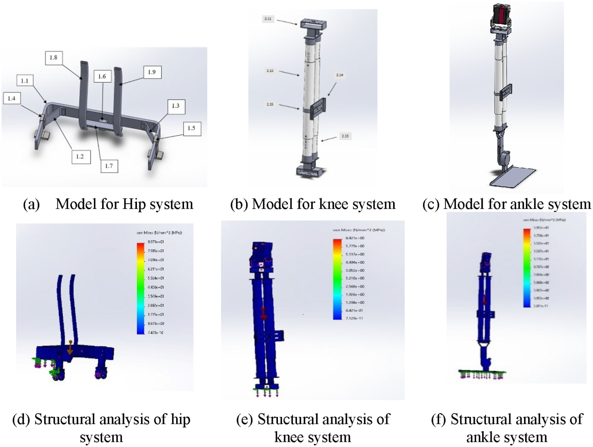
CAD model for hip, knee, and ankle systems, their corresponding structural analysis: (a) model for hip system, (b) model for knee system, (c) model for ankle system, (d) analysis of hip system, (e) analysis of knee system, and (f) analysis of ankle system.
Design optimization study
To ensure minimum weight of all components involved in the proposed DLEX, an optimization design study is performed for main components. Design variables are mainly the dimensional parameters that have the most significant effect in mass reduction of each component. Common objective function is to minimize the mass of each component. However, safety and structural analysis under loading conditions should be investigated to prevent failure. Constraining equation for all components is that; von-Mises stress (σ v ) should be less than the yield stress (σ y ) of 1060 Al alloy. In the following subsections, design optimization procedures for hip support frame and knee tube of DLEX are presented.
Optimization study for back support frame
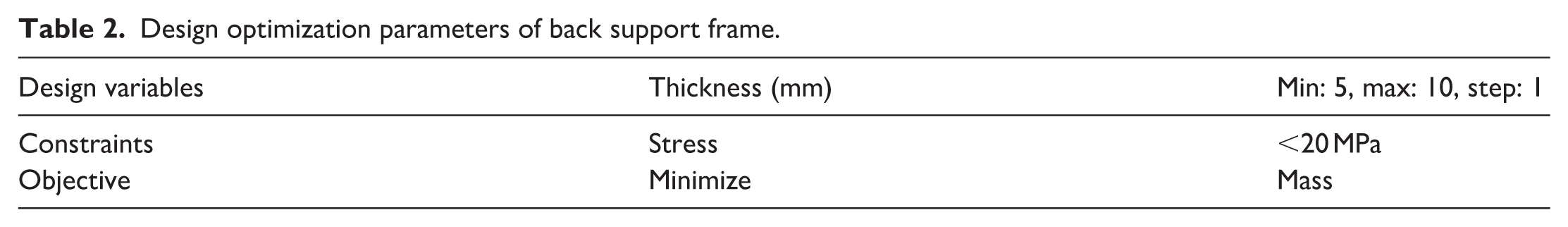
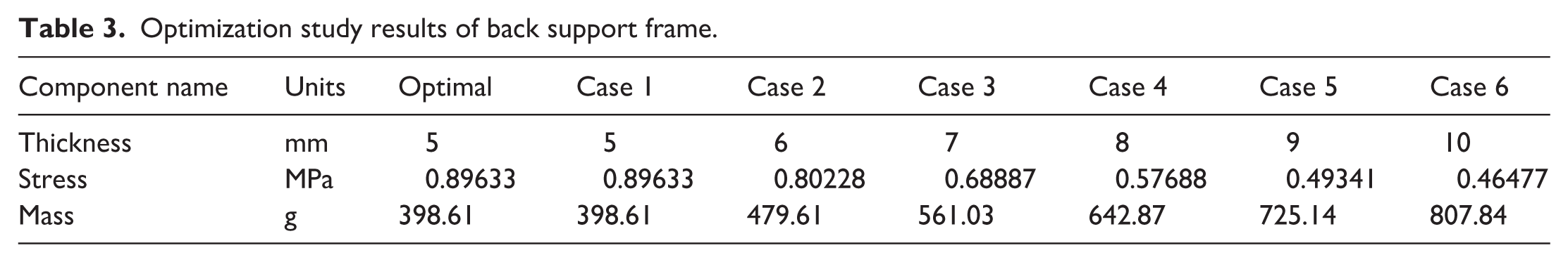
The back support frame initially has thickness of 10 mm and a mass of 807.84 g. Simulation of back support frame involves the following boundary conditions. The simulated model has a finite element mesh having 12,090 elements with element size of 6.6 mm. Applied material is AL 1060 alloy with yield strength of 27 MPa. Using a safety factor of 1.35, it is required that maximum equivalent stress do not exceed (σ y /1.35 = 20 MPa.) Fixed support is applied at the upper surface of the back support as the position of wearable human support. It is more important to consider compression load affecting back support. So that, reaction of DLEX weight and average human weight is about 75 kg. Taking the same safety factor of 1.35, the applied load can be simulated as 100 kg or 1000 N. Optimization variables, constraints, and objectives are summarized in Table 2. Table 3 presents study results including optimal solution. Figure 4(a) and (b) illustrates initial and optimal structural analysis of back support frame. Figure 4(c) and (d) illustrates displacement for initial and optimal solution.
Design optimization parameters of back support frame.
Optimization study results of back support frame.
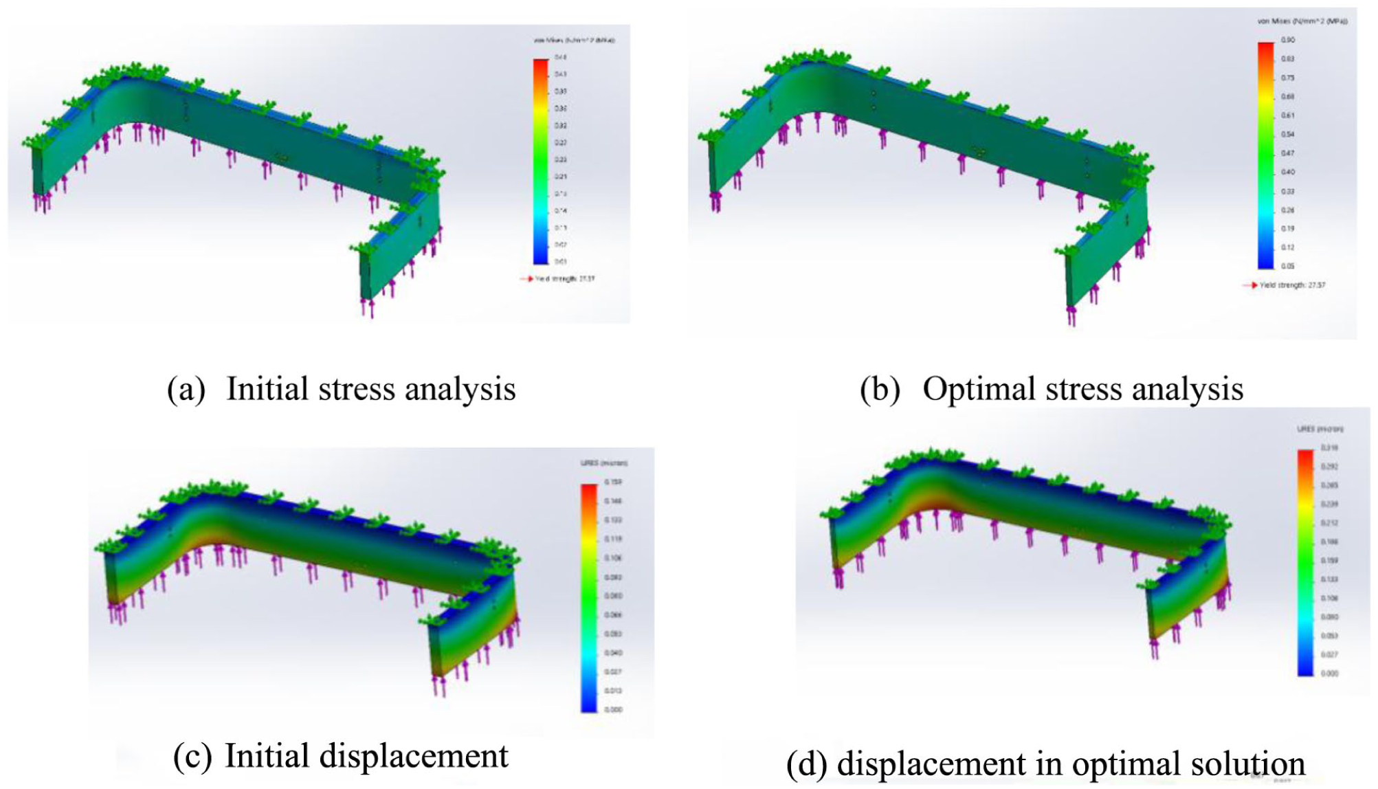
Optimization design study for back support frame: (a) initial stress analysis, (b) optimal stress analysis, (c) initial displacement, and (d) displacement in optimal solution.
Optimization study for knee tube
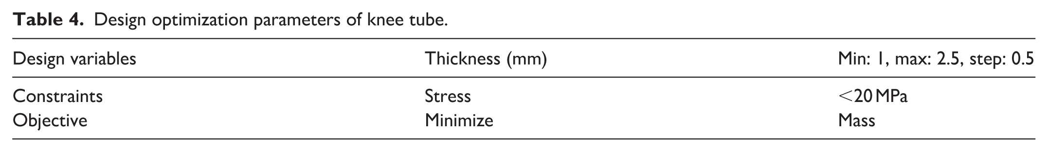
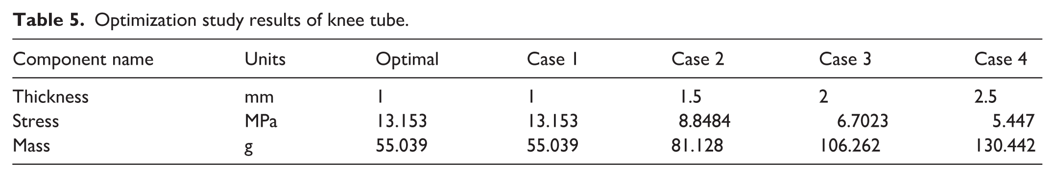
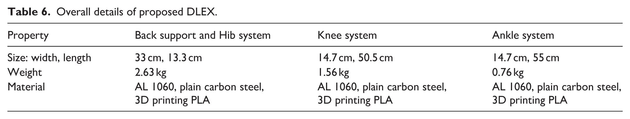
The knee tube initially has thickness of 2.5 mm and a mass of 130.44 g. Knee tube is supposed to be a rigid link that cannot be deformed under compression loads. The tube model has a finite element mesh having 7769 elements with element size of 3.9 mm. Considering that 500 N is applied to the whole knee system, therefore each knee tube is subjected to 250 N. Taking the same safety factor of 1.35, the applied load for each tube is 400 N. AL 1060 Alloy is also applied with the same conditions of back support frame. Optimization variables, constraints, and objectives are summarized in Table 4. Table 5 presents study results including optimal solution. Figure 5(a) and (b) illustrates initial and optimal structural analysis of knee tube. Figure 5(c) and (d) illustrates displacement in initial and optimal structural of knee tube. As a result of optimization study for main components, the total mass of the DLEX has been reduced to 4.95 kg. Overall details of proposed exoskeleton are summarized in Table 6.
Design optimization parameters of knee tube.
Optimization study results of knee tube.
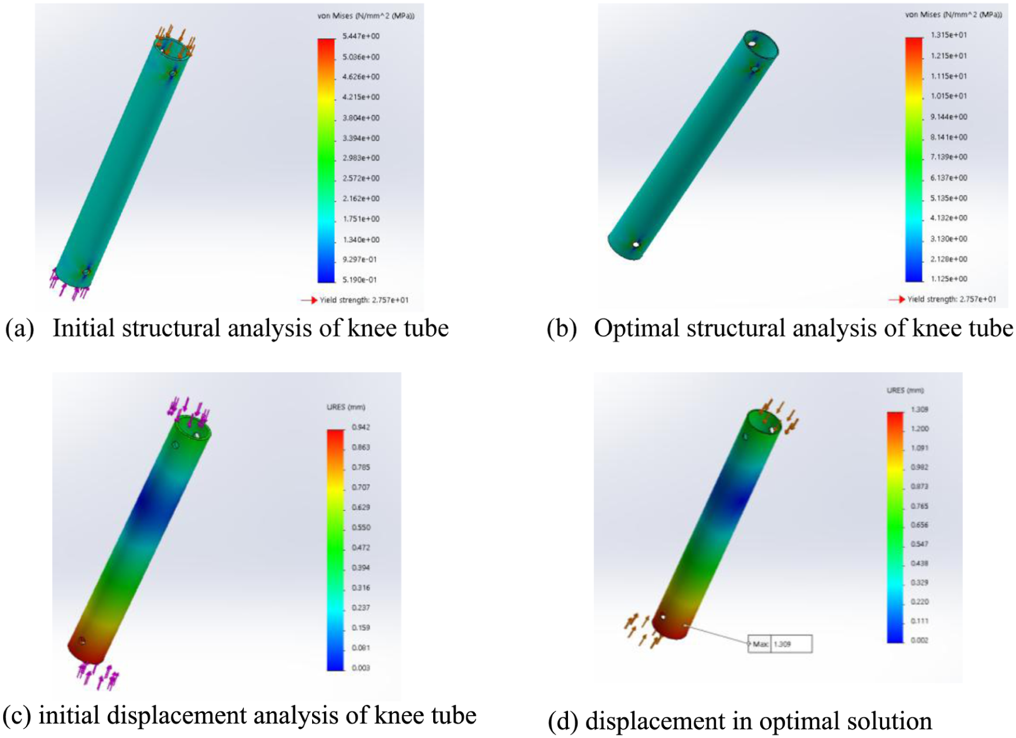
Optimization design study for knee tube: (a) initial structural analysis of knee tube, (b) optimal structural analysis of knee tube, (c) initial displacement analysis of knee tube, and displacement in optimal solution.
Overall details of proposed DLEX.
Mechanics of exoskeleton system and torque analysis
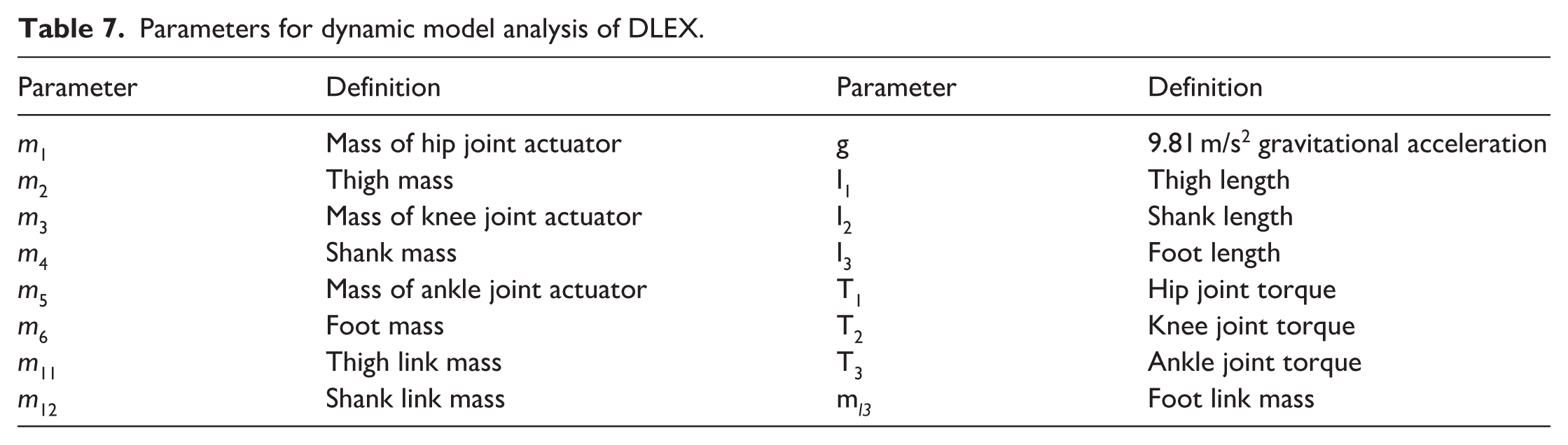
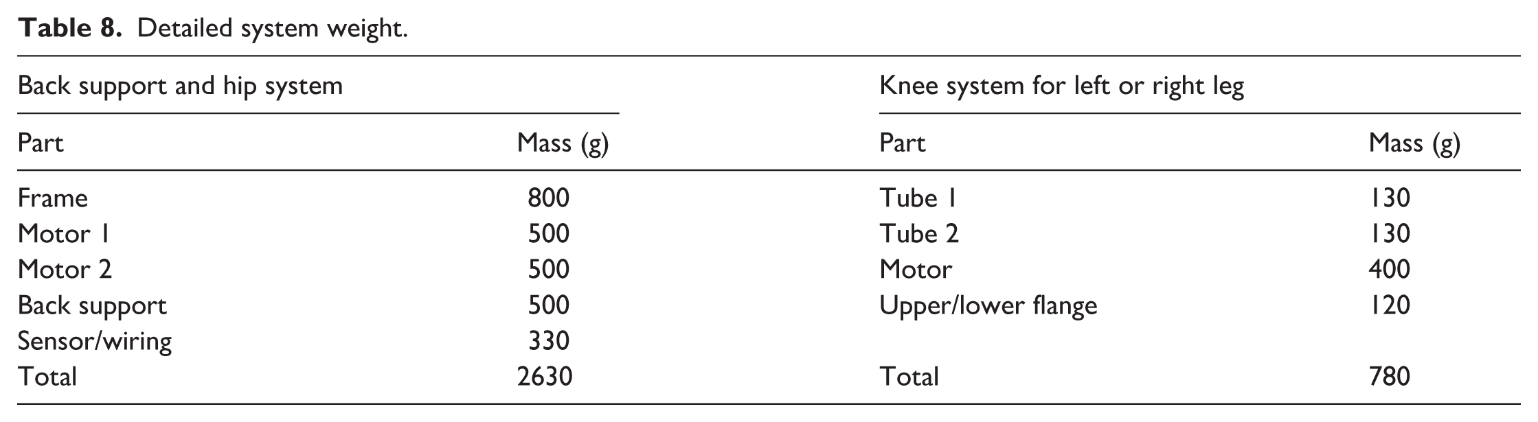
Kinematics of lower limb joints are used to describe movement and DOF of robotic exoskeleton joints. DOF of the hip, knee, and ankle joints in sagittal plane is closely related to the walking gait. Flexion/extension DOF at the hip and knee joints in the sagittal plane are taken as actively driven joint. Ankle DOF is taken as passively driven to keep stability of motion during walking. Dynamic analysis of the exoskeleton robotic system is performed to detect the relationship between movement state of the system and joint-driving torque during walking. Maximum torque of the exoskeleton hip joint is 50 Nm and that of knee joint is 30 Nm at average speed. 13 All parameters of model dynamic analysis are defined in Tables 7 and 8. However, free body diagram, shown in Figure 6, illustrates acting forces on different joints and links in DLEX system.
Parameters for dynamic model analysis of DLEX.
Detailed system weight.
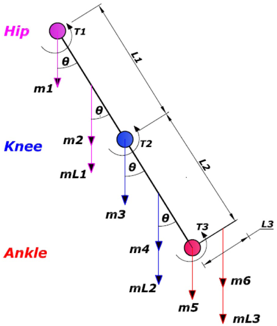
Free body diagram for hip, knee, ankle joints for torque analysis.
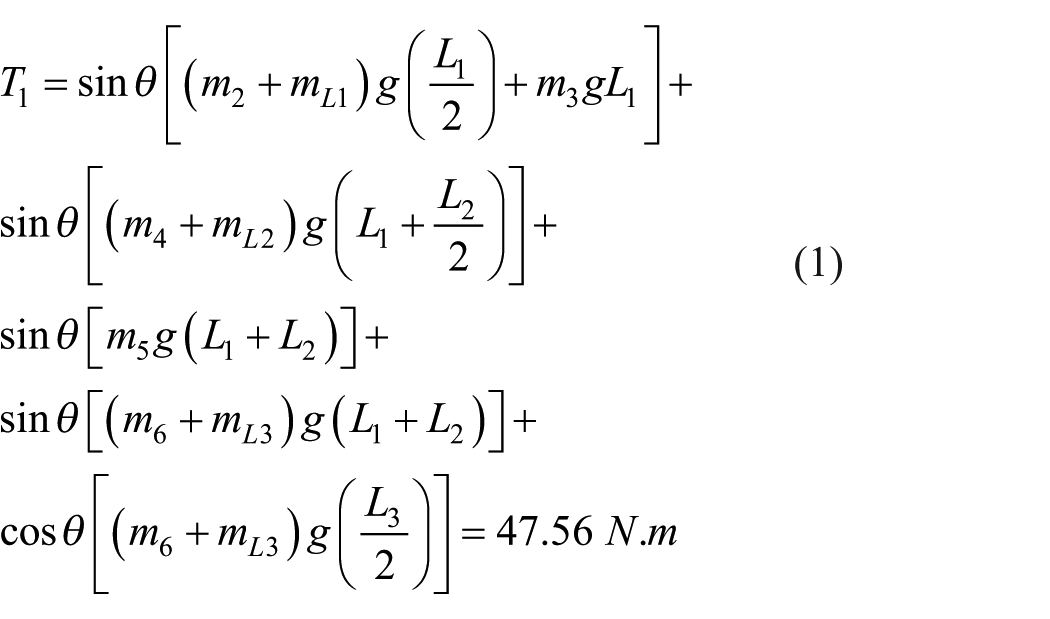
Hip joint moves in three ways: bending forward/backward, moving sideways, and rotating inwards/outwards. In daily normal life, these movements typically range from 0° to 100° in forward bending, sideways movement up to 45°, and rotation within a range of −25° to +25°. Hence, peak torque calculations at hip joint can be performed according to equation (1). 13
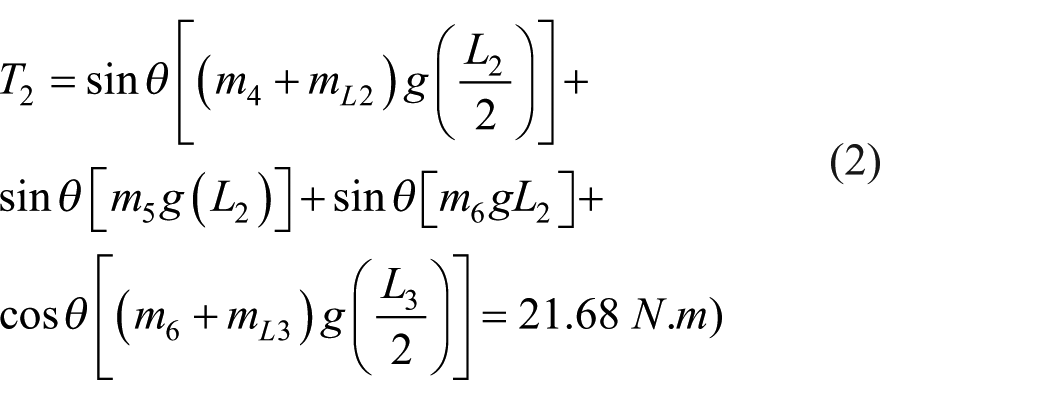
Knee joint primarily bends and straightens in the front-to-back direction up to 120°. So, torque calculations at knee joint can be performed according to equation (2). 13
Based on equations (1) and (2) peak torque required for hip and knee joints can be considered as 50 and 30 Nm, respectively, for safety considerations. However, for 35% assistance, peak torque for hip and knee joints is 16.3 and 7.7 Nm, respectively. Average torque is assumed to be 25% of the peak torque. Therefore, average torque required at hip and knee joints is 4.1 and 1.9 Nm, respectively.
Simulation with MATLAB/Sim-Mechanics
The kinematic performance of the robotic exoskeleton is related to all parameters of gait cycle. Therefore, simulation by MATLAB/Sim-Mechanics is carried out to assess the influences of these parameters. Parametric variables are used for mechanical properties such as mass, inertia, and other geometric dimensions for further modifications. A model has been created for leg mechanics and motion of DLEX as presented in Figure 7(a) and (b), respectively. The sequential procedures of walking system model are illustrated in Figure 7(c). Hence, 3D model for DLEX is created using multi body Sim-Mechanics.
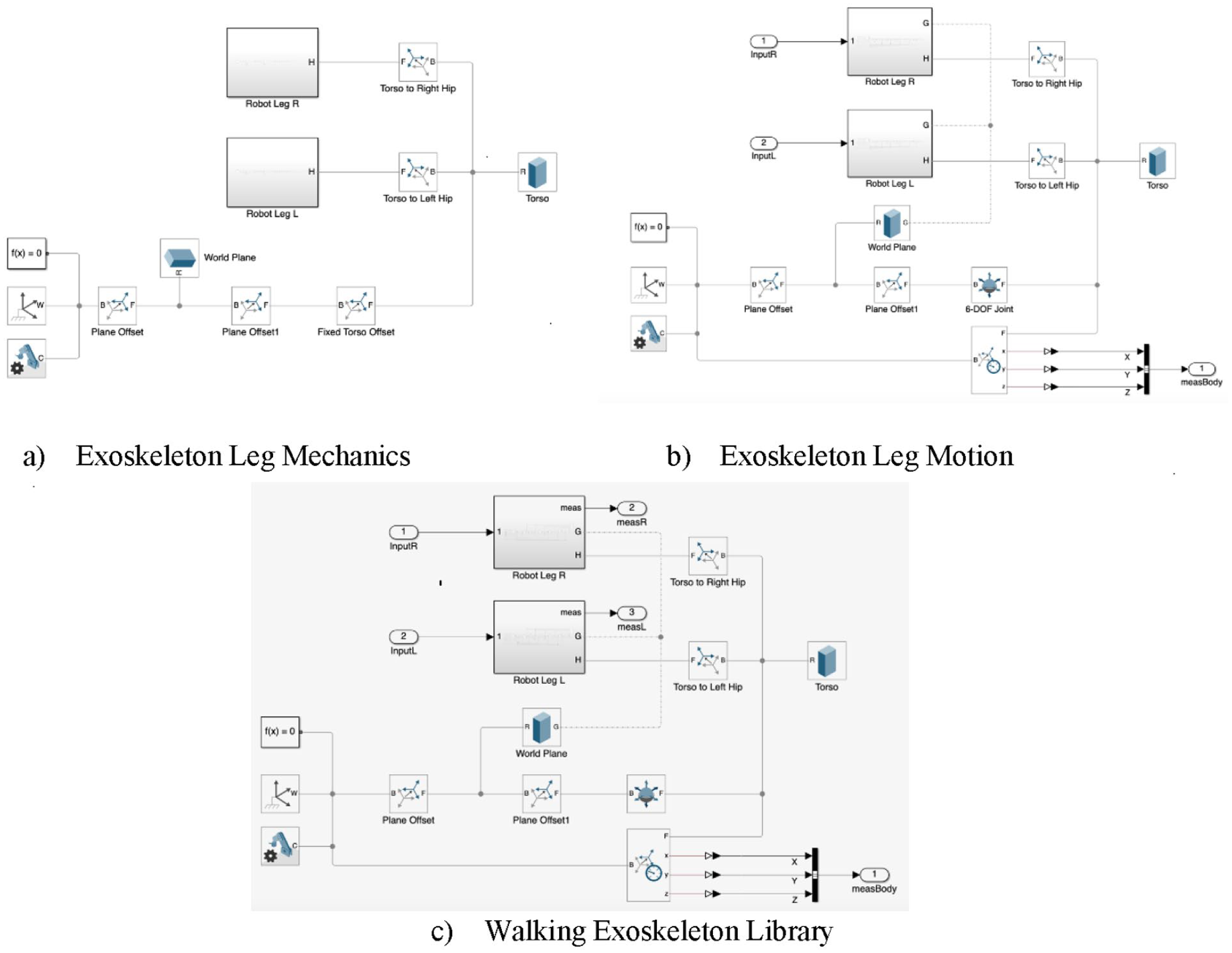
Walking DLEX Sim-Mechanics model: (a) exoskeleton leg mechanics, (b) exoskeleton leg motion, and (c) walking exoskeleton library.
Control algorithm of DLEX
It is important to develop effective control strategies for robotic exoskeletons that are used for motion assistance and rehabilitation based on the estimation of the human motion intention. As illustrated in Figure 8, the proposed control system configurations are based on active actuators at both hip and knee joints, microcontroller, feedback system, and power supply.
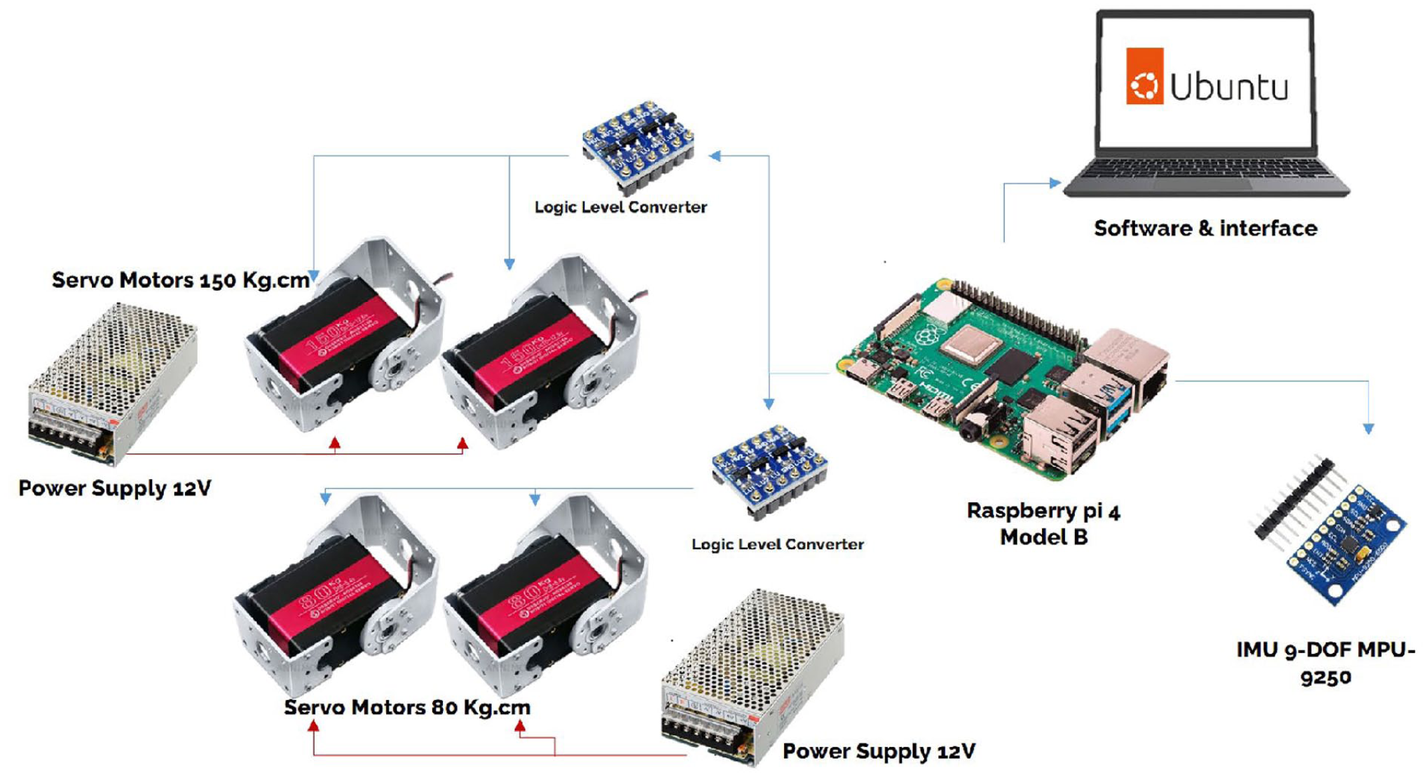
Control system configuration of DLEX.
Actuating and feedback systems
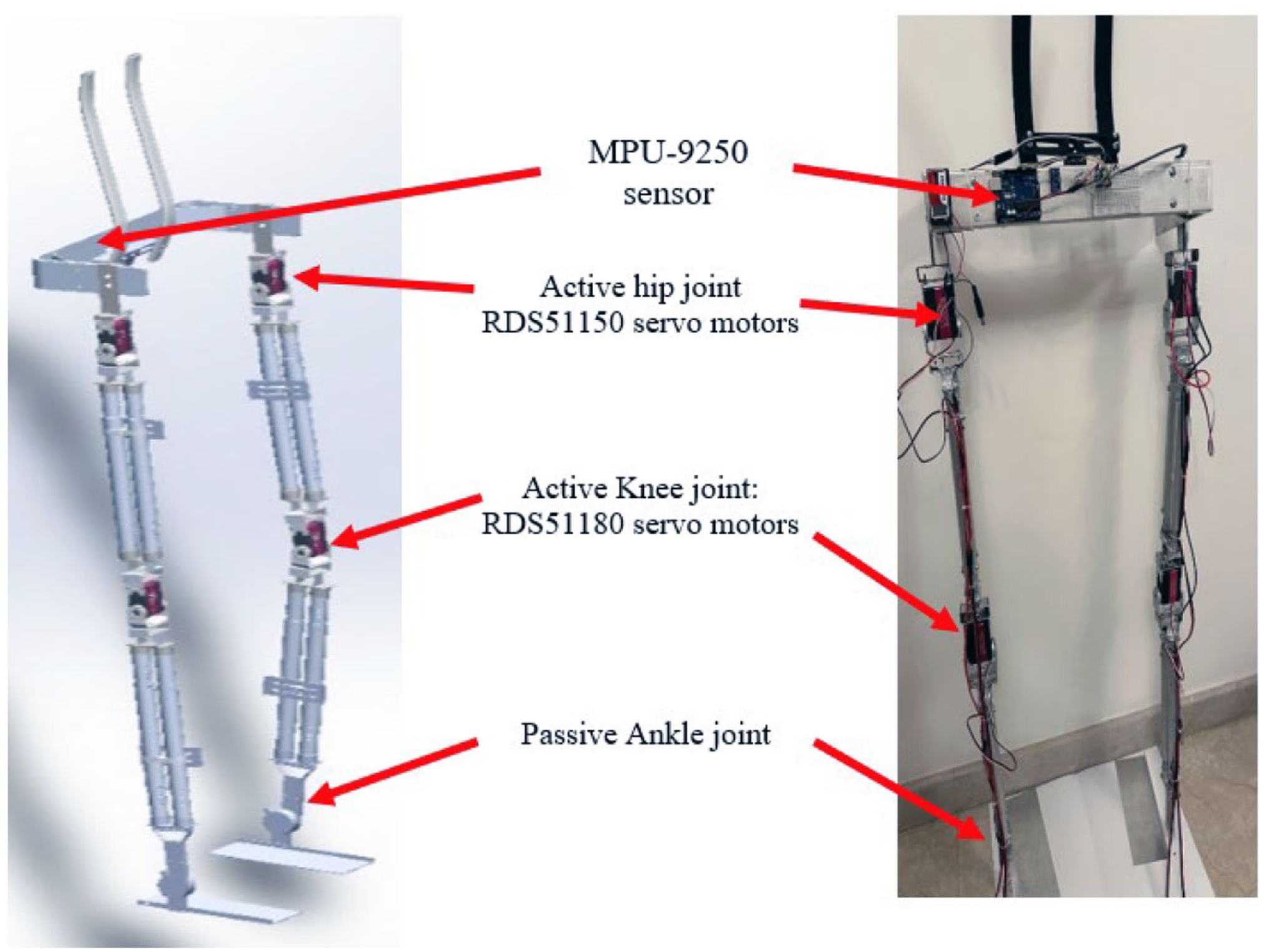
The main goal of rehabilitation process is to restore the lower limb motion to the normal levels. This target can be achieved by the torque generated by actuators. For 35% assistance for human rehabilitation, two types of servo motors are selected for hip and knee joints as illustrated in Figure 8. For hip joints, RDS51150 servo motors are used with a generated torque output up to17.6 Nm. For knee joints, RDS5180 servo motors are used with a generated torque output up to 14.7 Nm. That meets the required peat torque for hip and knee joints as described in Section 3.3. MPU-9250 sensor module is integrated into the exoskeleton to provide real-time feedback on limb orientation and movement as shown in Figure 9. That are essential for mimicking human gait and adjusting servo motor movements in the exoskeleton’s joints. MPU-9250 sensors include the capabilities of Gyroscope, Accelerometer, and Magnetometer.
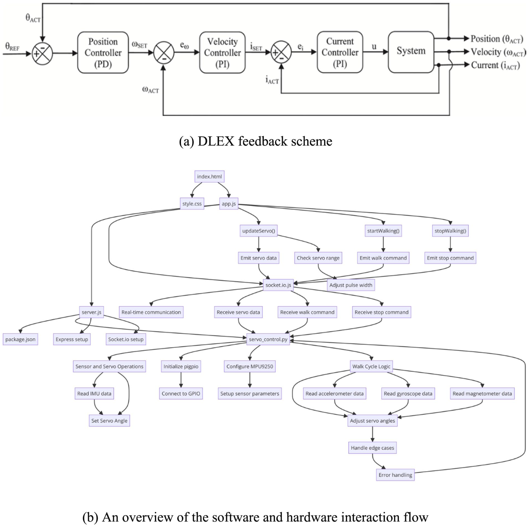
(a) DLEX feedback scheme and (b) An overview of the software and hardware interaction flow.
Microcontroller
The Raspberry Pi 4 Model B is applied as a microcontroller. The Raspberry Pi 4 Model B is equipped with a Broadcom BCM2711, Quad-core Cortex-A72 (ARM v8) 64-bit SoC clocked at 1.5 GHz, with 4 GB of LPDDR4-3200 SDRAM. A 64 GB microSD card is used for storage, providing substantial space for the operating system, software applications, logs during the exoskeleton’s operation. It includes comprehensive connectivity options such as Gigabit Ethernet, onboard Wi-Fi (2.4 and 5.0 GHz IEEE 802.11b/g/n/ac wireless), and Bluetooth 5.0. These features enable the Raspberry Pi to communicate seamlessly with other components of the exoskeleton, as well as external devices for configuration, monitoring, and updates. Micro-HDMI, USB 3.0, USB 2.0 ports are available along with a 40-pin GPIO header for connecting various sensors, actuators, and display modules. The Raspberry Pi continuously monitors DLEX for any signs unusual behavior. It manages safety protocols, implementing emergency shutdowns to maintain user safety and prevent damage to the system. Figure 9(b) illustrates an overview of the software and hardware interaction flow.
Software development and user interface
An integrated web-based software is established for real-time interaction with servo motors and sensors using C++ and Java script. Web-based software ensures that the hardware operates smoothly and effectively while translating sensor inputs into precise motor control. A user interface is designed using Python to be accessible for diverse needs as shown in Figure 10(a). Sliders controls are used to control the motion of active joints through modifying the angles of servo motors operation according to therapeutic movements as shown in Figure 10(b). This interface also fosters a proactive engagement of patients in managing their rehabilitation, which is a critical factor in enhancing the efficacy of recovery protocols.
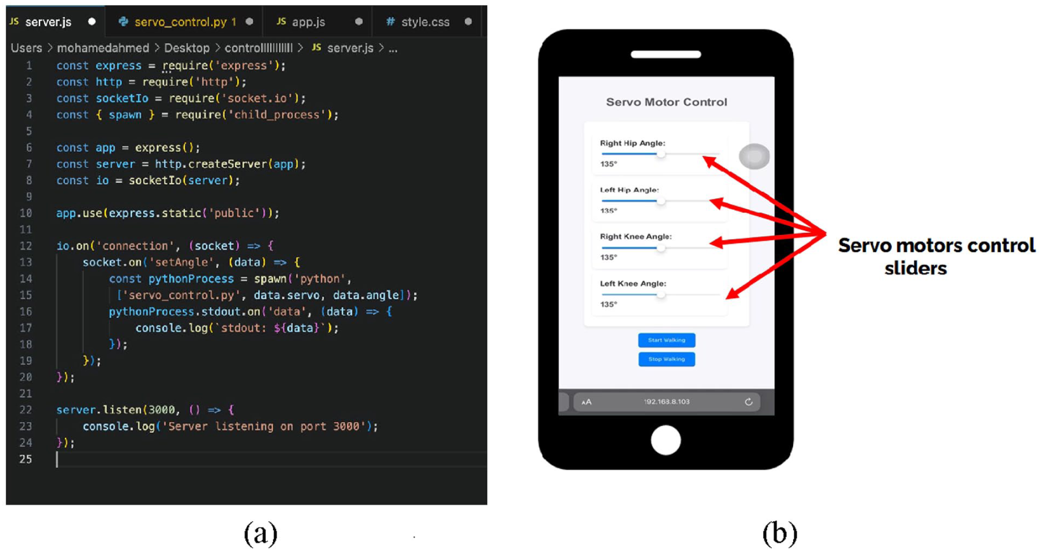
Software development: (a) sample of software coding and (b) user interface.
Power supply and safety circuits
Two industrial SMPS power supplies with safety circuits providing +12 Vdc/20 A output from a 220 Vac input are used for DLEX prototype. The strategic management of power supply and integration of comprehensive safety features ensure the reliability and safety of exoskeleton operation under various conditions. This will protect the electronic components and safeguard the user from potential hazards.
Results and discussions
Simulation results
Torque and angle profiles for hip and knee joints can be generated from Sim-Mechanics model presented in Section 3.3 as shown in Figure 11.
Simulated results of torque and angle profiles for hip and knee joints: (a) angle profile for hip joint, (b) torque profile for hip joint, (c) angle profile for knee joint, and (d) torque profile for knee joint.
Prototype implementation and testing
A prototype is constructed for DLEX according to the proposed model. It has 126 mm width at hip joint, and 100 mm at knee joint. The prototype components are manufactured using aluminum alloy 1060, carbon fiber plate to ensure lightweight. The implemented prototype of DLEX fits subjects from 1.60 to 1.90 m length that covers almost 90% of corresponding users. Figure 12 illustrates simulated CAD model and manufactured prototype with attached components.
Simulated CAD model and implemented prototype with attached components.
In DLEX testing, the movement range of exoskeleton is about 120° in flexion for the hip joint. While movement range of the exoskeleton are 120° in flexion and 30° in extension for the knee joint. That range covers the required movement of limb joints. Figure 13(a) to (c) presents practical motion test for hip and knee joints.
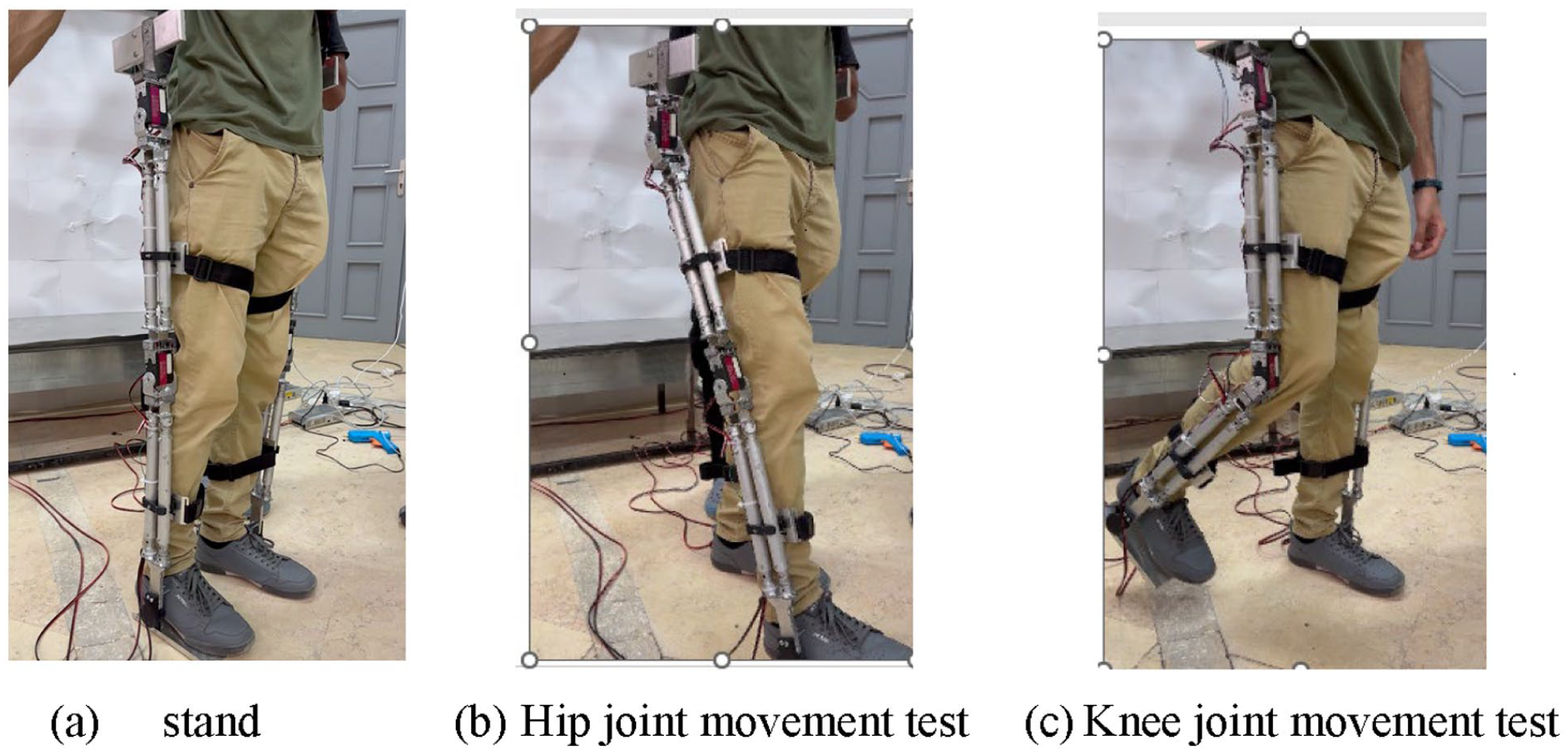
Practical motion test for hip and knee joints: (a) stand, (b) hip joint movement test, and (c) knee joint movement test.
Performance validation
Performance of DLEX as a real power-assisted device should be verified. So that, comprehensive experiments are conducted for the whole system. The purpose of these experiments is to test the movement of exoskeleton joints related to the human gait including torque and angle functions.
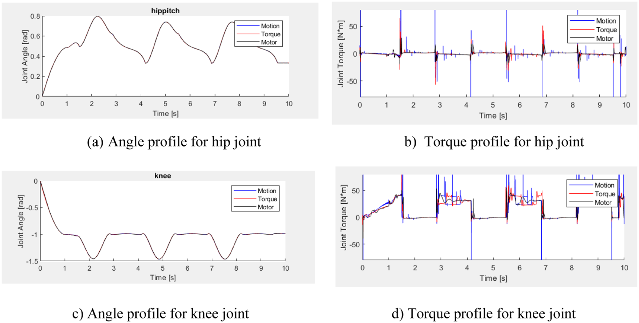
Twenty trials for five subjects are tested. For a subject average height of 170 cm, and average weight of 70 kg, the experimental test showed that the prototype of DLEX validates the human gait cycle in both stance and swing phase as illustrated in Figure 14. Angle profile curve of hip and knee joints are presented in Figure 15(a) and (c), respectively. Blue curve is the simulated angle profile where red curve is the actual output joint angle of the exoskeleton. Torque profile curve of the hip and knee joints are presented in Figure 15(b) and (d), respectively. Blue curve is the simulated torque profile where red curve is the actual output joint torque of the exoskeleton. Using IMU 9-DOF MPU-9250 Sensor that detect the orientation and angular velocity of links. Then actual torque can be detected by considering the motor power. The control interface enables user to adjust the movement of active joints through sliders controls.
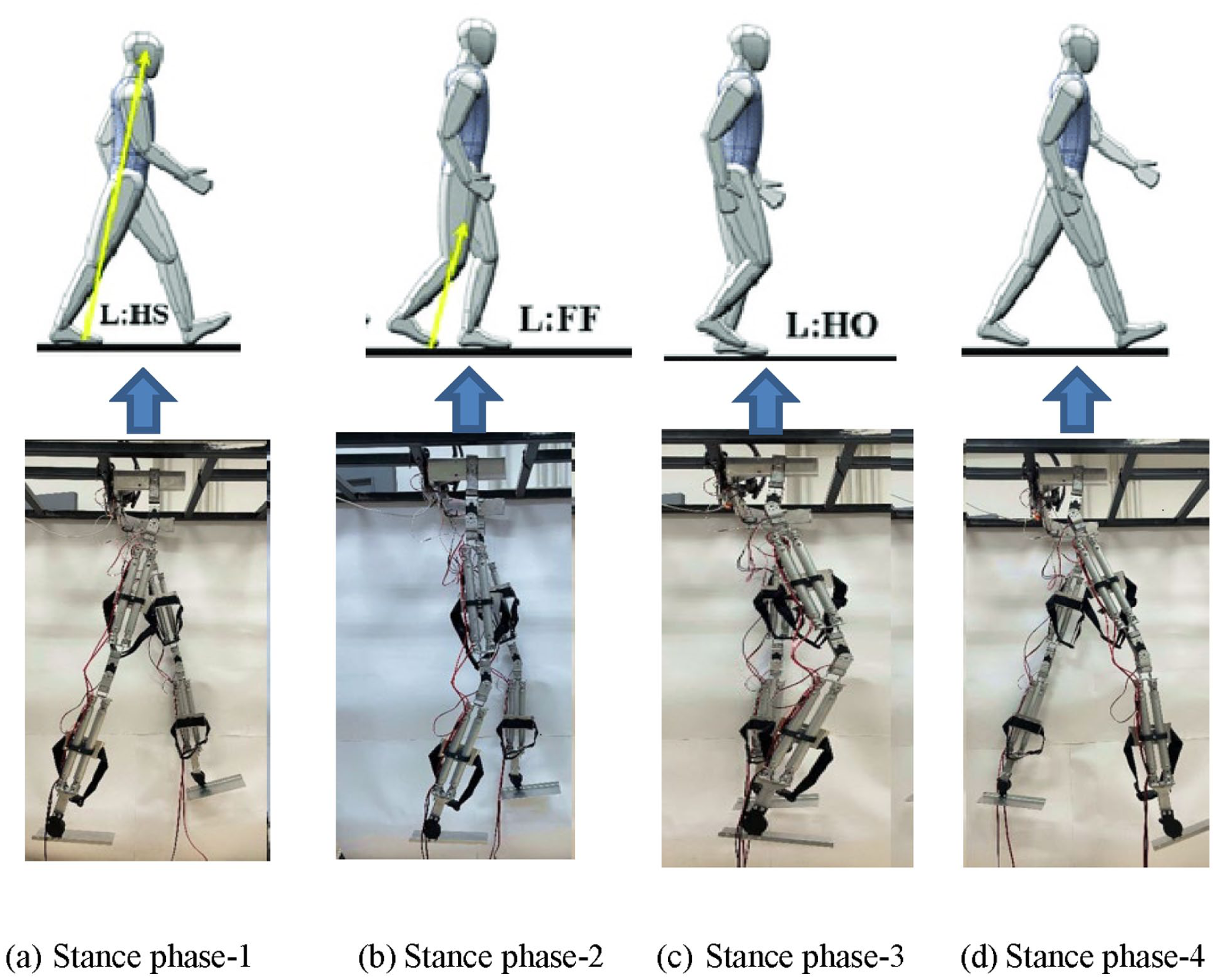
Performance validation experiment for DLEX prototype: (a) stance phase-1, (b) stance phase-2, (c) stance phase-3, and (d) stance phase-4.
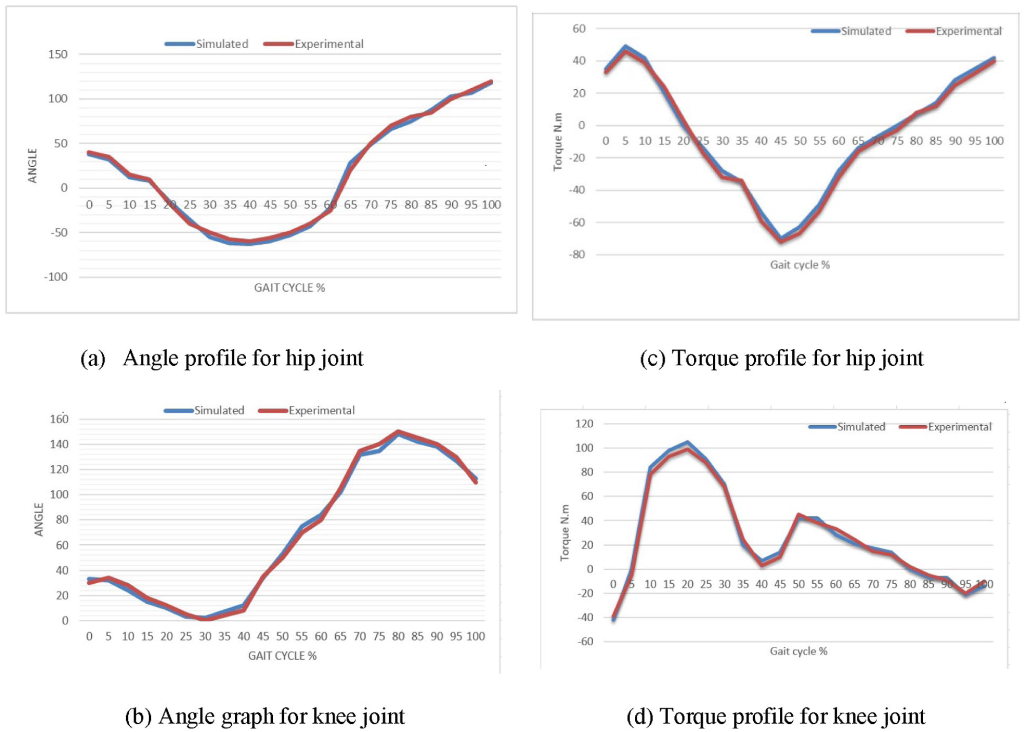
Experimental versus simulated results for torque and angle profiles related to gait cycle of hip and knee joints: (a) angle profile for hip joint, (b) torque profile for hip joint, (c) angle graph for knee joint, and (d) torque profile for knee joint.
Conclusion
Rehabilitation is an essential process that help patients for fast recovery. A new design for a lower limb double leg exoskeleton, DLEX, has been introduced. Lightweight, minimum cost, and simple control are the mean features of the proposed DLEX. A safe mechanical design has been developed using SolidWorks followed by design optimization study to minimize total mass. A Simulink model has been created to simulate DLEX kinematics, motion, torque, and angle profiles for hip and knee joints. An integrated control system has been conducted using web-based software for real-time interaction with servo motors. An experimental prototype has been implemented with a smart control application. The proposed DLEX validates proper results with real and simulated results for hip and knee joint motion profiles. Therefore, the proposed design can be used in therapy recovery centers or even at home for elder people.
Footnotes
Acknowledgements
The authors are grateful to Future University in Egypt (Cairo, Egypt) for providing all the required facilities to carry out the present research. Also, authors are grateful to M Fathy, L Hassan, H Yasser, I Elsayed, Y Ashour, M Moataz for their great help in experimental and testing work. The authors would like to acknowledge the Deanship of Graduate Studies and Scientific Research, Taif University for funding this work.
Author contributions
Conceptualization, HE; methodology, HAB, KMA, FIA, AAA, and HE; software, MH and HE; validation, HAB, KMA, FIA, AAA, and HE; formal analysis, HE and MH; investigation, HAB, KMA, FIA, AAA; resources, MH and HE; data curation, MH and HE; writing—original draft preparation, HE; writing—review and editing, MH and HE; visualization, MH, HAB, KMA, FIA, AAA, and HE; supervision, MH and HE; project administration, HE and MH; funding acquisition, MH, HAB, KMA, FIA, AAA, and HE. All authors have read and agreed to the published version of the manuscript.
Declaration of conflicting interests
The authors declared no potential conflicts of interest with respect to the research, authorship, and/or publication of this article.
Funding
The authors disclosed receipt of the following financial support for the research, authorship, and/or publication of this article: This research was funded by Taif University, Saudi Arabia.
Consent to participate
Informed consent was obtained from all subjects involved in the study.