
Abstract
In order to match physiological characteristics, the application of pulsating rotational speed in blood pumps has become popular. This places greater demands on the motor of the blood pump, necessitating low power, rapid response and compact dimensions, among other considerations. In consideration of the characteristics inherent to the slotless BLDC motor, this paper proposes the implementation of a slotless stator as a replacement for the slotted stator in a magnetic-hydrodynamic double levitated axial blood pump. Initially, the slotless stator was conceived in accordance with the theory of slotless motors, incorporating helical windings and meeting the drive capacity requirements of the blood pump. The torque exerted on the rotor of the slotted stator motor and slotless stator motor was then compared through the application of the finite element method. An experimental system was constructed for the purpose of measuring the difference in performance between the two motor types. The attributes, the speed characteristics, the power and the temperature of the stators of the two motors were detected. The findings indicate that the slotless motor exhibits a reduced size, diminished speed fluctuations, expedited speed response, yet concomitantly exhibits almost double the power consumption and a more substantial temperature increase in comparison with the slotted motor.
Introduction
As posited by Tu et al., 1 ventricular assist devices (VADs) have the capacity to substitute for heart function, whether in a partial or complete capacity, and for a temporary or long-term duration, for patients suffering from heart failure. As a significant component of VAD, the blood pump has advanced to the third generation in a period exceeding half a century. The development of a blood pump capable of replacing the human heart with a high degree of perfection remains a considerable distance away. This is due to the presence of complications, including but not limited to haemolysis, thrombus formation and neurological events. A plethora of studies have been conducted on the structure, 2 material 3 and control system of blood pumps, 4 with the objective of enhancing their performance.
The motor is an integral component of the blood pump, and its function is directly related to the pump’s hydraulic and control performance. The technology of BLDC motors in blood pumps has reached a sufficient level of development for the design of the motors to be considered mature. Consequently, research has been focussed on the control system rather than the motor design itself. The majority of studies in this field are concerned with the control system, and the physiological signals, flow rate and pressure, to name but a few factors, that the system is able to monitor. Proportional integral derivative (PID) 5 control is a widely utilised method for the accurate regulation of speed in blood pumps. As demonstrated in the study by Golesorkhie et al., 6 field-oriented control (FOC) exhibited effective performance in mitigating the torque cripple induced by motor phase commutation, thereby reducing energy dissipation due to vibration. In order to adapt to physiological characteristics, blood pumps have now evolved from a constant speed to a pulsating mode.7,8
It is imperative that the pulsatile blood pump adheres to the predetermined pattern of speed changes within one cardiac cycle, which is typically 0.8 s. The requirement for the motor to possess a rapid speed response is imperative. The miniaturisation of the blood pump is advantageous for the implant, but it is imperative that the rotor speed is increased to ensure sufficient pressure and flow rate are achieved (the Impella 2.5 model can reach 51,000 rpm). 9 The utilisation of slotted motors in the majority of blood pumps was driven by the requirement for higher driven torque. In comparison with slotted motors, slotless motors offer certain advantages, including reduced torque ripple, decreased cogging, diminished vibration, reduced noise and enhanced smooth operation and constant torque linearity. 10 These motors are well-suited for applications requiring compact designs and high operational speeds. It has been determined that the torque ripple can be disregarded in the context of slotted motors of constant speed blood pumps. However, for pulsatile blood pumps, the torque ripple could have notable effects on smooth speed adjustment and low-noise applications.
The operation of the blood pump motor results in the generation of heat. Consequently, the blood and the tissues surrounding it are subjected to an increase in temperature. The safe temperature for blood heating is below 43 ℃. 11 The motor of the blood pump must not only satisfy the hydraulic requirement, but also demonstrate optimal performance in terms of dynamics and energy efficiency.
In this paper, the design of a slotless direct current (DC) brushless motor for a self-developed magnetic-hydrodynamic double levitated axial blood pump 12 is presented. The design is based on the three-dimensional electromagnetic semi-analytical and finite element method (FEM). This study aims to provide a comparative analysis of the drive performance of slotted and slotless motors in the context of blood pumps. This analysis is conducted through simulations to ensure a comprehensive and precise evaluation of the motors’ performance. The experimental system, incorporating prototypes of two distinct motor types, has been constructed. Subsequent measurements are then taken of the parameters, speed characteristics and thermal performance of the two motor types during operation. Finally, the performance of the two motors is discussed.
Model and method
The blood pump and it’s slotted motor
The schematic and prototype of the blood pump are shown in Figure 1. The magnetic force exerted by two pairs of permanent magnet rings located between the front and back guide vanes and the impeller has been shown to be capable of balancing the fluid force. The hydrodynamic pressure generated by a variable rotating impeller can support the impeller’s gravitational force. As demonstrated in Figure 2, the stator of the slotted motor of the blood pump comprises six windings. The rotor, which is a cylinder filled with a pair of magnetic poles radially, is integrated with the impeller. The slotted motor has the capacity to supply the blood pump with a driven torque for an impeller that rotates at a constant speed of 8000 rpm. The structural parameters of the motor will be provided subsequently in order to facilitate a clear comparison with the slotless motor.
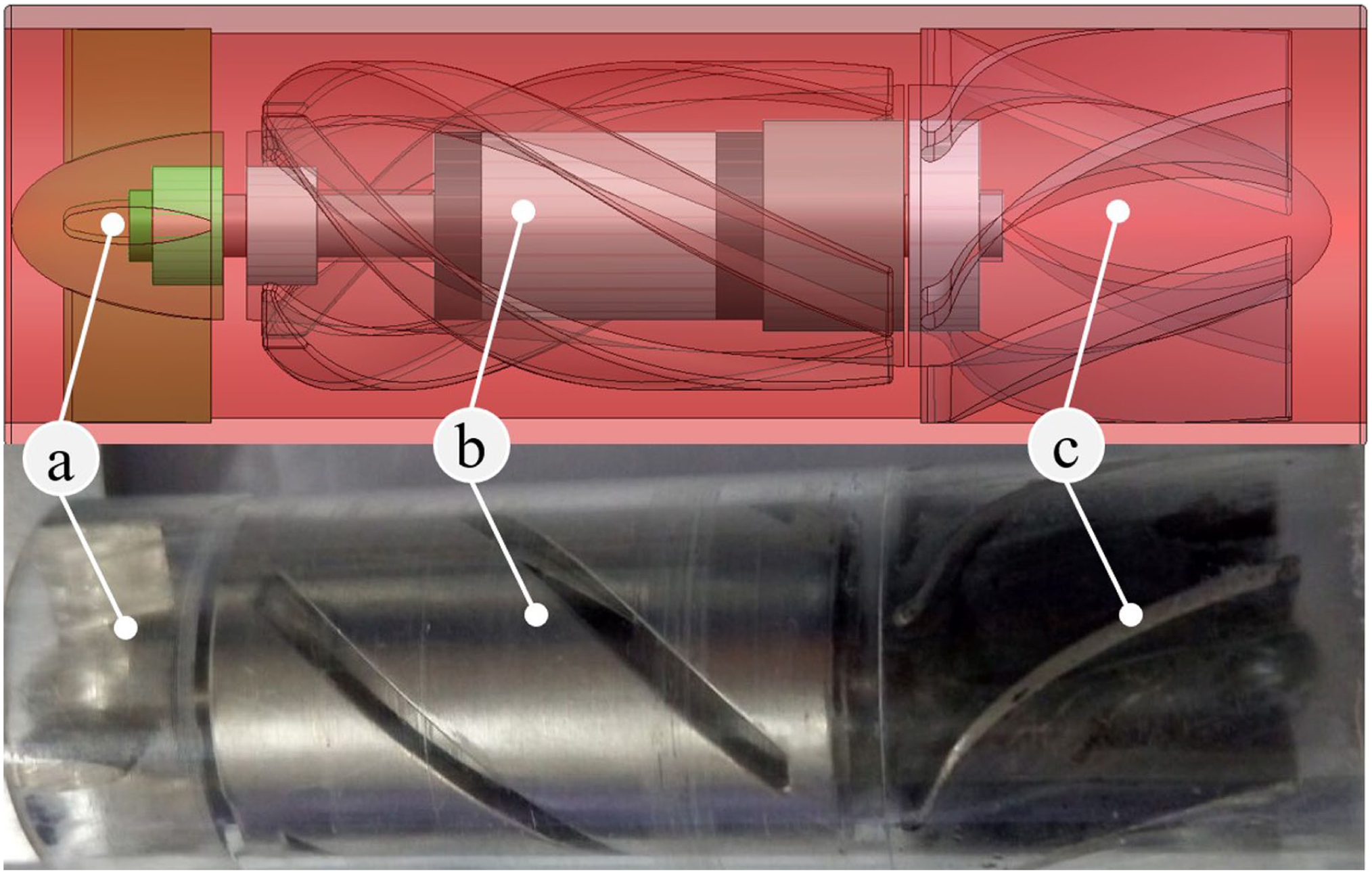
The schematic (up) and protype (down) of the blood pump: (a) the front guide van, (b) the rotor impeller, and (c) the back guide van.
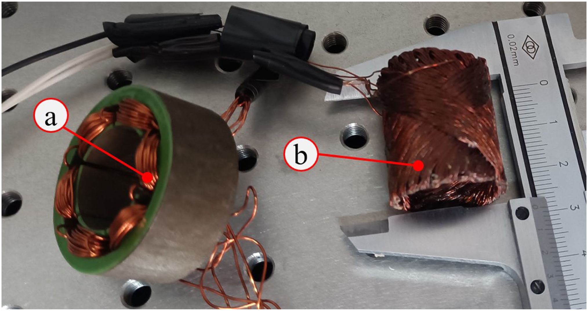
The stators of the motor: (a) the slotted stator and (b) the slotless stator.
The design of slottless motor
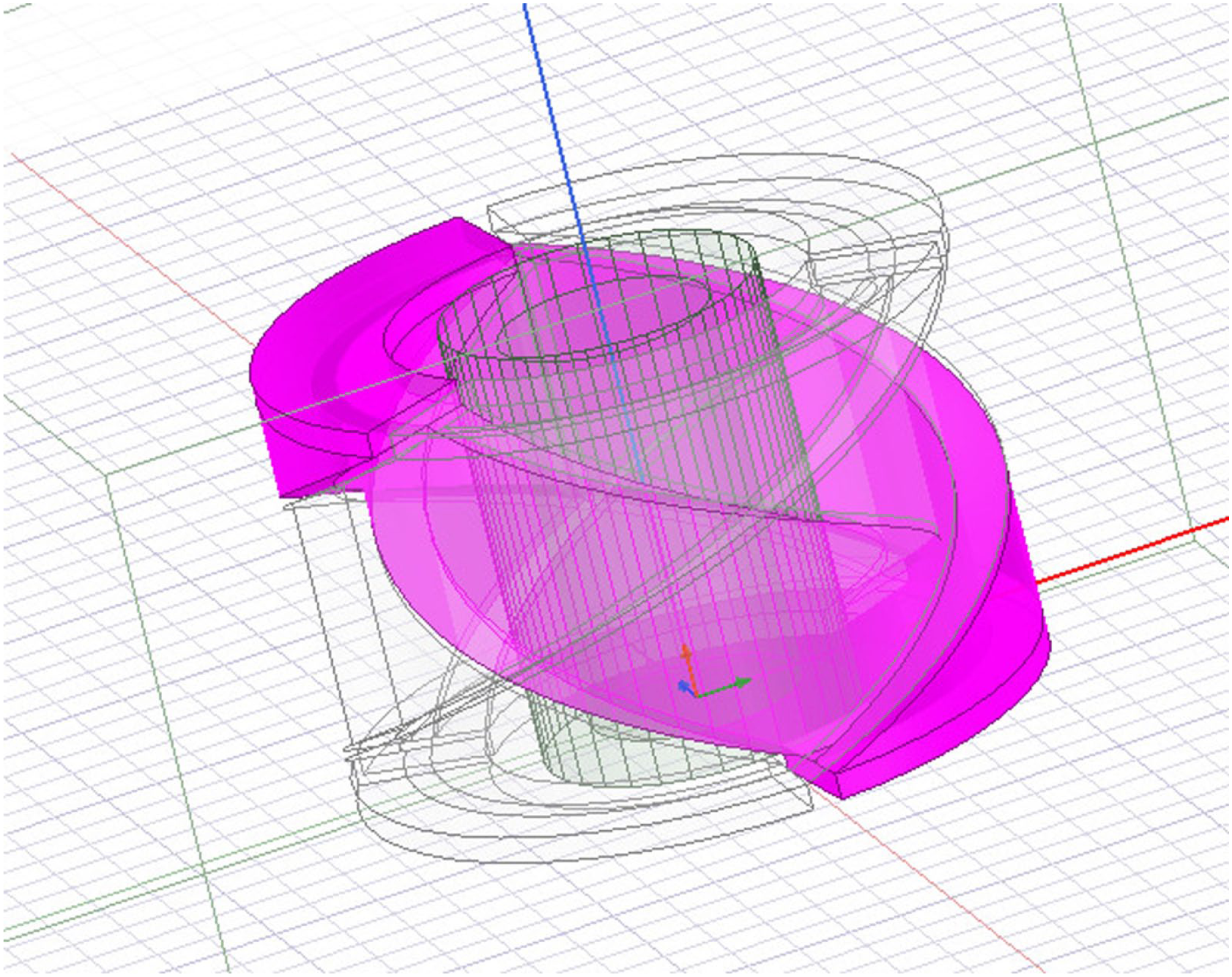
In contrast to the slotted motor, there is no stator core of laminated steel to which copper wire is wound. A plethora of slotless winding configurations exists; this paper examines the helical variety, which is the most prevalent. The winding model is depicted in Figure 3.
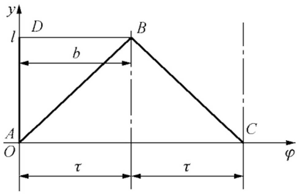
The model of the helical winding of the slotless motor.
For helical winding, the average back electric magnetic field (EMF) Eacph (V) can be calculated from 13 :
where, l is the axial length of armature of slotless motor, r (the unit is m, first take 0.01 for the calculation) is the radius of the armature, W (= 80) is the total turns of the winding, Bδ (the unit is Gs, first take 6000 for the calculation) is the magnitude of magnetic flux density of air gap and n (= 8000 rpm) is the rotating speed of the rotor.
The average armature current of winding Iacph (A) can be determined by 13 :
where U (= 18 V) is the applied voltage, Ra (first take 2 Ω for the calculation, and verify it later) is the thermal resistance of the winding.
The average electromagnetic torque of winding Temcph (Nm) is 13 :
The Temcph is 0.005 Nm, which is the driven torque demand. The relationship of r and l can be solved by the three equations simultaneously. The configuration of the stator’s helical windings is determined by the rotating speed, the size of the permanent magnet in the rotor, the working voltage, the manufacturing process and the driven torque demand.
The initial parameters of the slotted stator are determined by theoretical calculations. And then, the finite element parameter scanning method is utilised in the simulation of motor design. The objective is to model the torque and loss of the motor, with the parameter being the size of the stator. The specific design content and methods will be published later. The parameters of both the slotted motor and the slotless motor are presented in Table 1. The design of the stator is based on a simplified analytical model. However, in order to ensure optimal functionality of the motor, it is necessary to analyse its working performance in greater detail.
The parameters of the slotted motor and the slotless motor.
The fnite element analysis (FEA) of motors
The 3-D FEA is an effective tool for motor analysis. The slotted motor and slotless motors are modelled in SOLIDWORKS 2023 and subsequently imported into ANSYS Electronics Desktop 2018. The Transient solver of Magnetic in Maxwell 3D design of ANSYS Electronics Desktop 2018 is applied to simulate the motor. The Inverter Circuit, which is edited in Maxwell circuit editor, is used for driving the motor. It is evident that the circuit’s connection is synchronised with the rotation speed of 8000 rpm. The material of components, band, region must be set up. The configuration of the slotless motor is illustrated in Figure 4. The excitation is loaded to the corresponding current density; for slotted motors, this is 0.5 A and for slotless motors, it is 1 A for each turn of windings. The parameters to be solved are the moment on the permanent magnet, the cogging torque, the solid loss, the core loss and the eddy current loss of the motor at the rated speed, and the simulated time is 16 ms. The motors’ startup process under rated load are also simulated.
The model of the slotless motor in ANSYS Electronics Desktop.
Experiments
As demonstrated in Figure 5, an experimental system was constructed to accurately measure the performance discrepancy between the two motor types. The rotor, which is a permanent magnet N52 with a diameter of 8 mm and a height of 15 mm, was set up on the shaft, which had a diameter of 3 mm. The shaft was affixed to the two bearings, with one end being connected to the torque meter (DYN-200; Dayang Co., Ltd., China) via a coupling. The load in question was generated by the hysteresis clutches (HB-002M; Tianyu Hengchuang Sensing Technology Co., Ltd., China). The rotors were controlled by a FOC BLDC motor driver (OID-MINI-RS485; OIDelec Co., Ltd., China). The pulse-width modulation (PWM) frequency is 25 kHz. The corresponding software was able to detect motor parameters, record various operating parameters of the motor and perform different operational controls on the motor. The temperature of the stator of the rotor was measured using a thermocouple thermometer (model TA612C; manufactured by TASI Co., Ltd., China). The requisite voltage for the system was provided by a linear DC regulated power supply (UTP3305-II; UNI-T Co., Ltd., China). The vernier caliper with precision up to 0.02 mm is applied in the process of the assembling of the rotor permanent magnet and the stators, and the errors of the axial and radial positional are within 0.02 mm.
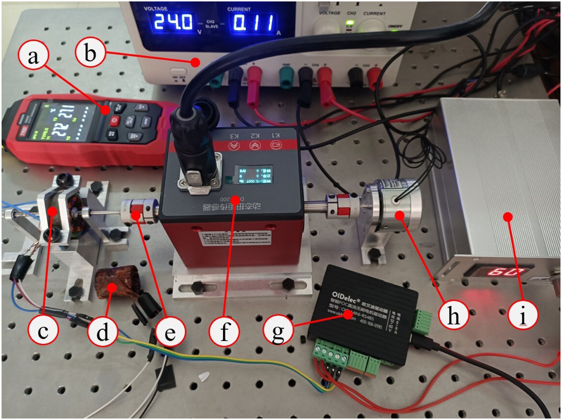
The motor performance test experimental system: (a) the thermocouple thermometer, (b) the DC power supply, (c) the stator of the slotted motor, (d) the stator of the slotless motor, (e) the coupling, (f) the torque meter, (g) the motor driver, (h) the hysteresis clutches, and (i) the controller of the hysteresis clutches.
The current of the hysteresis clutches was 0 A, corresponding to 0 Nm load, when the motor was initiated. Subsequently, the motor speed attained 8000 rpm with a load of 0.005 Nm, an outcome facilitated by the adjustment of the PID. The sampling frequency is 16 kHz, and the proportional-integral (Kp) and proportional-derivative (Ki) constants of the current loop are 0.0198 and 283.48, respectively. Following the stabilisation of the synchronous speed, an adjustment was made to the current, resulting in a reduction of the speed to ~6500 rpm. The alterations in rotation speed were documented and stored by the software.
Two temperature measurement points were identified for the slotted motor: one on the outer surface (T1) and the other within the winding (T2). The temperature measurement point for the slotless motor was located in the winding (TL). The data pertaining to the temperature of the motor operating at a constant speed of 8000 rpm and a load of 0.05 Nm was meticulously recorded by the software, that is, included with the instrument. The repeat time of all the experiments is 5.
Results and discussion
Results
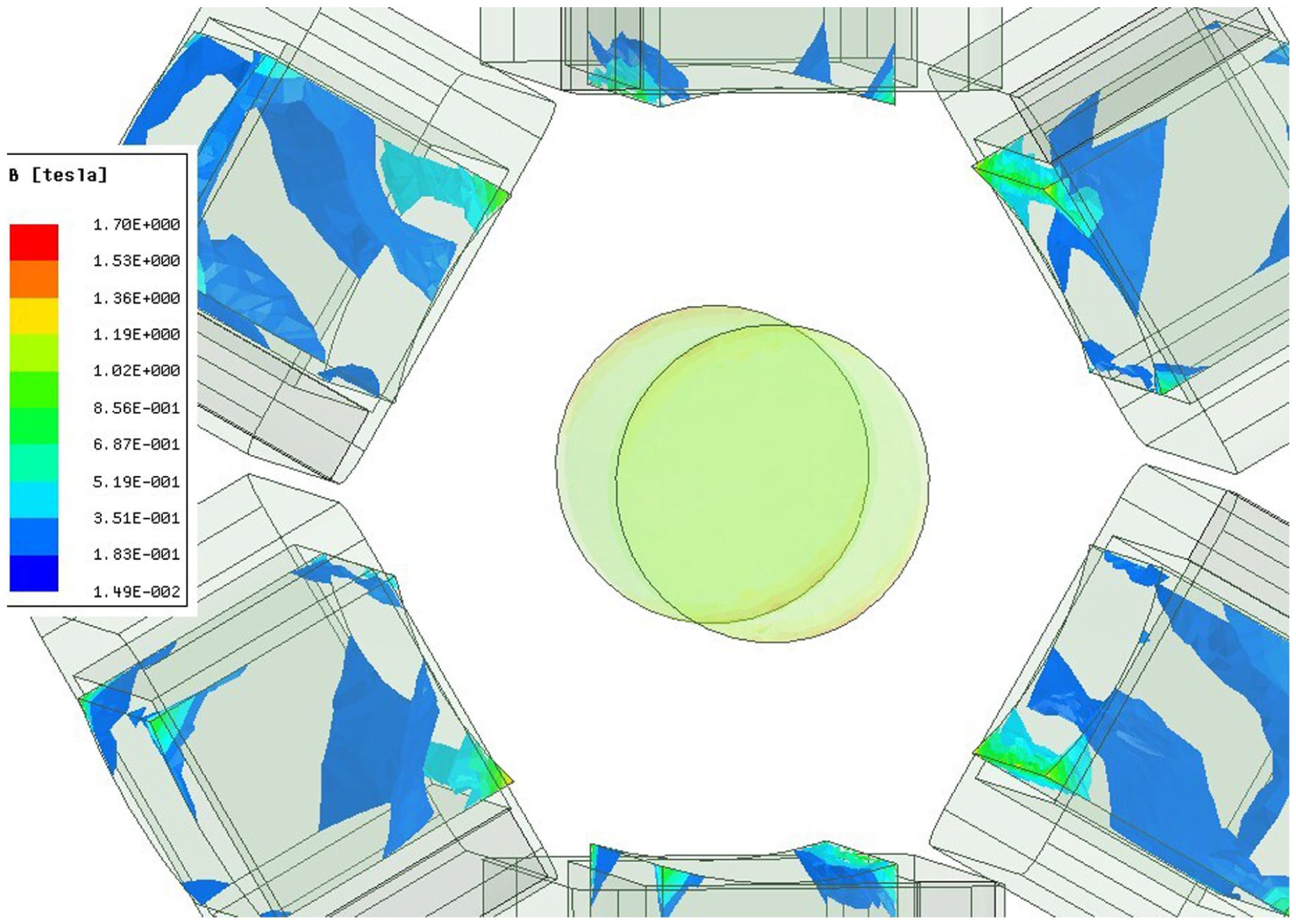
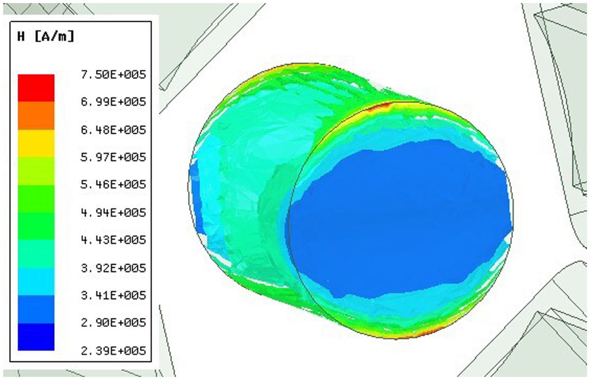
As illustrated in Figures 6 and 7, the contours represent the magnitude of the magnetic flux density (Mag_B) for both slotted and slotless motors. As illustrated in Figures 8 and 9, the contours represent the magnitude of the magnetic field strength (Mag_H) of both slotted and slotless motors. The entirety of the contours represents the simulation results at the time of maximum torque. The Mag_B is calculated to verify magnetic circuit design and identify saturation points. In the case of the slotted motor, the magnetic field is primarily situated within the stator teeth, with the maximum intensity occurring at the periphery of the stator teeth. The objective of the designed stator is to ensure a uniform distribution of Mag_B. This is achieved by the classic stator through the retention of a thin layer of stator material at the edges. In the case of the slotless motor, the absence of a stator results in an increase in magnetic resistance. However, this does not give rise to an aggregation problem of Mag_B. The maximum Mag_B for two motors is 1.7 and 1.3 T, respectively. It is important to note that both of these values are lower than the saturation value of 2.0 T. It was observed that no hot spots were detected in the stator of either motor. The Mag_H can be applied to assess demagnetisation risk, with the primary focus being on the values on the surface of the permanent magnet. The maximum Mag_H for two motors is 6.03 × 10⁵ and 7.50 × 10⁵ A/m T, respectively. It is evident that both of these are lower than 8.36 × 10⁵ A/m, which is the coercive force of the permanent magnet.
The contours of the Mag_B of the slotted motor.
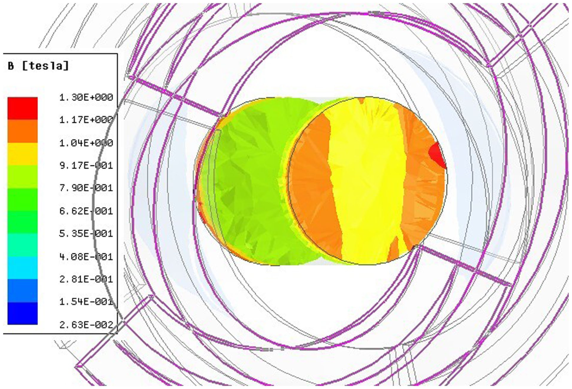
The contours of the Mag_B of the slotless motor.
The contours of the Mag_H of the slotted motor.
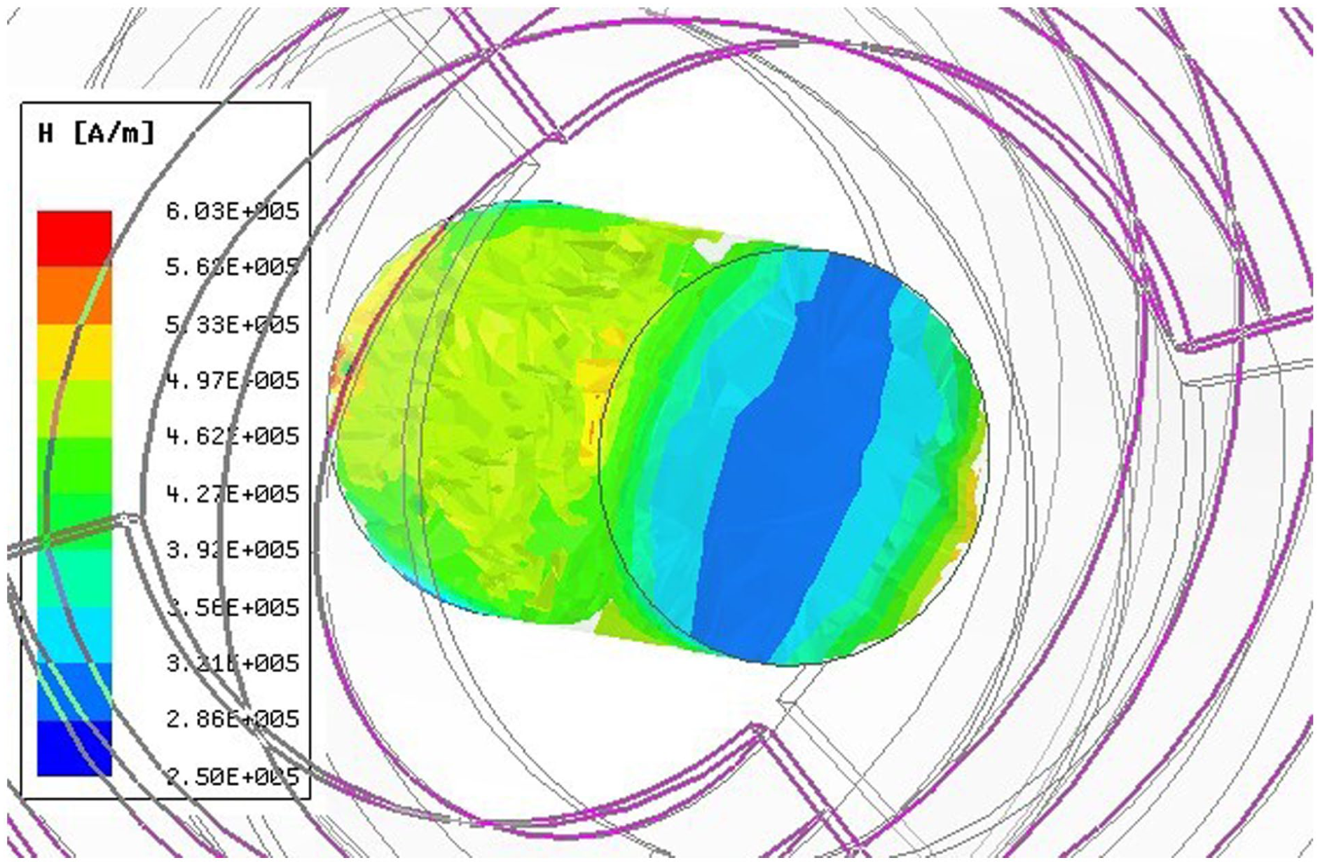
The contours of the Mag_H of the slotless motor.
As demonstrated in Figure 10, the variation of the magnetic field intensity at a specific point on the surface of the two rotors’ permanent magnet axial midpoint over time (B-T) has also been the subject of research. It has been demonstrated that the curves of the B-T of both slotted and slotless motors exhibit periodic changes, akin to a sine curve. This finding is consistent with the observations made in conventional motors. The hysteresis effect inherent in the stator of the slotted motor results in a smoother curve, while the slotless motor exhibits minor fluctuations due to the phase change of the circuit. It is evident that both the curves of B-T at the reference point of the two motors are altered in a smooth manner, with the absence of flat tops or sharp peaks. The amplitude of the slotless motor is less than that of the slotted motor.
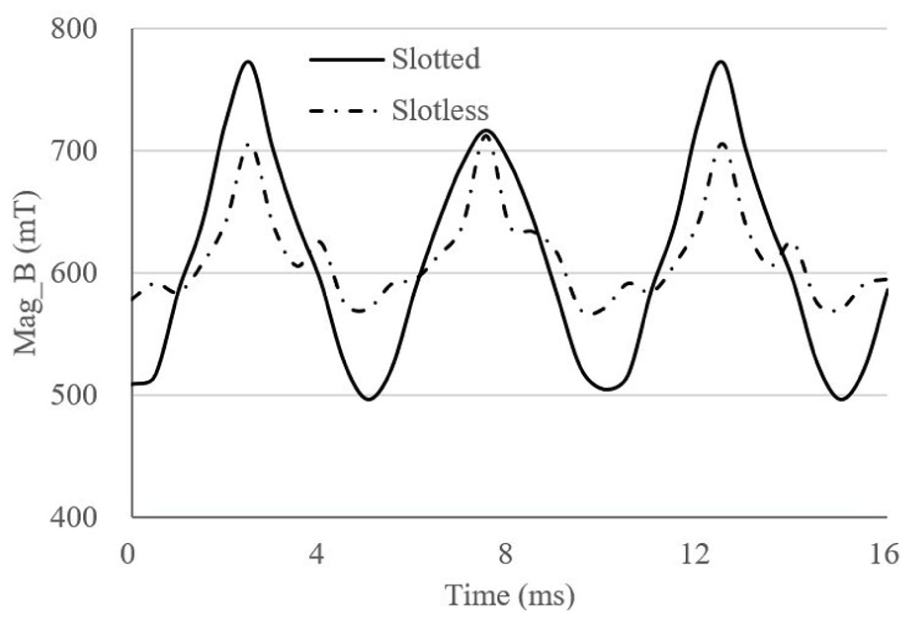
The B-T of a specific point on the surface of the two rotors’ permanent magnet axial midpoint.
The on the harmonic content of the back-EMF of the slotted motor (IV_C) and the slotless motor (IV_CL) simulated results is shown in Figure 11. The fundamental frequency is 50 Hz. The main components of the back-EMF of two motors are same, corresponding to the rotation speed. Fo the hysteresis effect of the slotted stator, the Mag of the first order component of the slotted motor’s back-EMF is smaller than the slotless motor’s, and the Mag of other order components of the slotted motor’s back-EMF are bigger.
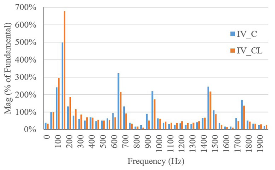
The harmonic content of the back-EMF of the slotted motor (IV_C) and the slotless motor (IV_CL) simulated resluts.
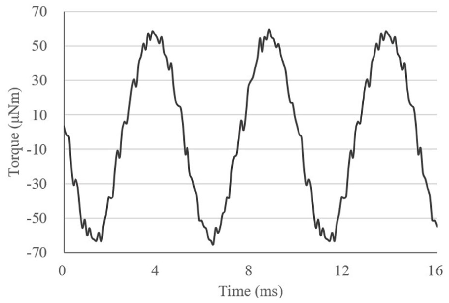
The simulated results of torque acting on the rotors of the slotted motor (TS) and slotless motor (TL) are shown in Figure 12, respectively. The torque exerted on the rotors of both motors undergoes periodic fluctuations. The operational lifespan of the slotted motor is twice that of the slotless motor. It is evident that there are three peak points in one period of a slotted motor, and only one peak point in one period of a slotless motor. Despite the fact that the current of each turn of windings of the slotless motor is twice that of the slotted motor, the maximum torque of the slotless motor is only 1.3 times that of the slotted motor. For minimum torque, the slotless motor’s is above 0, but the slotless motor’s is below 0. The torque ripple is defined as the ratio of the difference between the maximum and minimum torque values to their sum in the paper, and the torque ripple of the slotted motor and the slotless motor is 136.4% and 78.9%, respectively. The cogging torque of the slotted motor is shown in Figure 13. For the material of the stator (DW465_50), the cogging torque generates when the permanent magnet rotor rotating. The cogging torque of the slotless motor is 0 (for the value is constant 0, not given in the figure), because there is no stator.
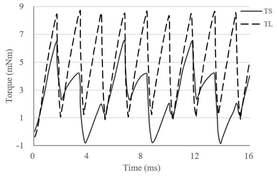
The simulated results of torque act on the rotor of the slotted motor (TS) and the slotless motor (TL).
The simulated results of cogging torque of the slotted motor.
The simulation indicates that the solid loss is 0.25 mW, the core loss is 5.87 mW and the eddy current loss is 3.77 mW for the slotted motor at the rated speed and load. However, it should be noted that for slotless motors, all these values are equal to zero, given the absence of a stator core. The theoretical calculation indicates that the copper loss of the slotted motor and slotless motor is 0.06 and 2.1 W, respectively. The mechanical loss is mainly the friction of bearings and torque meter, about 0.2 W (Mechanical transmission efficiency is 95%).
The simulation research was conducted on the two motors starting with a rated load. The variation of speed over time is demonstrated in Figure 14. The final speed of the slotted motor and the slotless motor is 9080 and 9340 rpm, respectively. The rotational speed equilibrium of the slotless motor is attained more rapidly than that of the slotted motor.
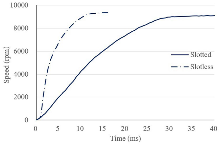
The variation of speed over time of the slotted motor and the slotless motor in the process of the start.
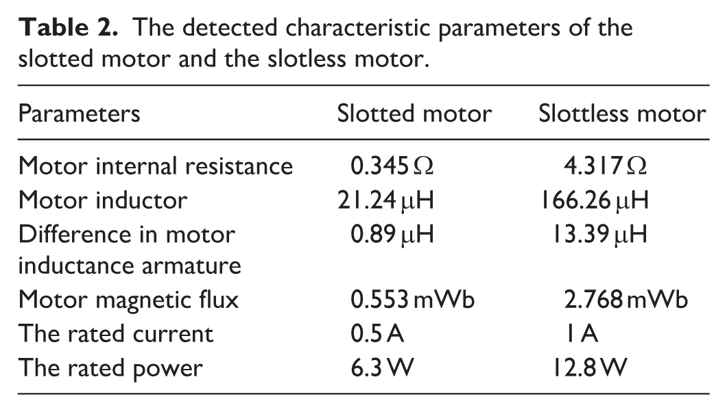
The attributes of the two motors detected by the software are listed in Table 2. The parameters of slotless motors are known to be an order of magnitude larger than those of slotted motors.
The detected characteristic parameters of the slotted motor and the slotless motor.
As demonstrated in Figure 15, the experimental results illustrate the speed characteristics of the slotted motor (R_C) and the slotless motor (R_CL). To facilitate comparison on the same horizontal axis, the timing of the results was standardised. The average rotation speed of slotted motor is 8080 ± 25 rpm, with a fluctuation of 1.3% ± 0.2%. And for slotless motor, the values are 8026 ± 14 rpm and 0.5% ± 0.1%. Compared to the simulation research, the speed is a little small, for there is mechanical friction in the experimental system. The speed of the slotted motor can be reduced from 8000 to 6000 rpm by decreasing the current. The process of the speed of the slotted motor reduced from 8000 to 6000 rpm by decreasing the current takes 5 ± 0.8 s. For the slotless motor, the time is recorded as 0.4 ± 0.1 s. The power of the slotted motor is 6.3 ± 0.3 W, whereas that of the slotless motor is 12.8 ± 0.2 W at a rated speed with a load of 0.005 Nm. Corresponding motor efficiency is about 66.7% ± 0.7% and 32.8% ± 0.5%, respectively.
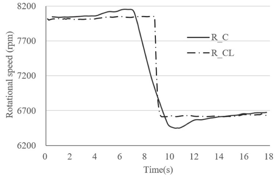
The speed characteristics of the slotted motor (R_C) the slotless motor (R_CL).
As demonstrated in Figure 16, the temperature of two distinct categories of motor stator was observed. The ambient temperature of the environment during the experimental procedure was recorded as 28.2 ℃ ± 0.5 ℃. The temperature rise of T1 is 3.0 ℃ ± 0.3 ℃, and the time required to reach temperature stability is 213 ± 7 s. For T2, the temperature rise is 1.3 ℃ ± 0.2 ℃ with the time required of 194 ± 4 s to reach temperature stability. For TL, the temperature rise is 16.9 ℃ ± 0.9 ℃ with a time required of 518 ± 8 s to reach temperature stability.
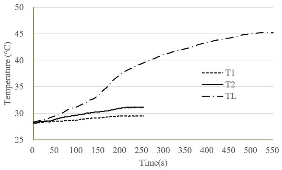
The temperature of the stator of the motor changed over time.
Discussion
According to the contours of the Mag B, Mag H and the B-T of the slotless motor, the design of the slotless motor is feasible. But this distribution, characterised by ‘saturation at the tooth tips and undersaturation in the tooth bodies and yoke’, leads to a significant amount of armature reaction flux flowing into the tooth tips, thereby becoming the primary heat source outside the stator windings. It has been demonstrated that tooth tip saturation leads to distortion of the air gap magnetic field waveform and an increase in harmonic content. This, in turn, results in additional torque ripple and electromagnetic noise. The high density of magnetic field lines in the air gap is indicative of a significant magnetic flux density gradient in that area, suggesting the potential presence of local magnetic resistance torque or leakage flux. This phenomenon reduces the utilisation of the permanent magnets, leading to a decrease in the motor’s output torque at a constant current. As illustrated in Figures 8 and 9, the magnetic flux density gradient in the edge region, denoted by Mag H, approaches a value of 750 kA/m. For permanent magnets exhibiting medium to low coercivity (particularly those whose coercivity declines at elevated temperatures), this approaches the safety limit, thereby posing a risk of irreversible demagnetisation. It is evident that the motor’s permanent magnet torque and maximum torque capacity will undergo a permanent reduction, which will in turn result in increased torque ripple and deteriorated vibration and noise. For these two types of stator motors, due to the large air gap and the requirement for high speed and compact size, both the magnetic flux and its distribution are in a less favourable state compared to conventional motors.
The weight of the rotating components in the measurement system, the installation fit errors of the device and so on, all affect the measurement results. However, during the measurement, only the type of stator is changed, and the difference between the results of the two measurements is very obvious, so the errors caused by the experimental system have little impact on the results.
The comparison between the simulation study and experimental study of the balance speed after startup has proven the reliability of the research. The slotted stator is characterised by high magnetic flux density and superior torque density, a consequence of its concentrated windings. This renders it advantageous for high-power applications. The efficiency of the slotted motor is examined in this paper, with the results indicating that it can reach 66.7% ± 0.7% at its rated speed and load in the case of a large air gap (see Table 1 for details of the structural parameters). However, the inherent cogging torque generated by slot harmonics introduces torque ripple, which limits the precision in medical devices or servo systems, leads to several peak points in one period, the negative torque during phase change and longer response time for speed change in the paper. In the case of the embedded winding, the total length of the wire is reduced, thereby decreasing the resistance.
The elimination of the stator yoke in slotless designs has been demonstrated to result in the suppression of cogging torque, enabling smooth operation, the reduction in stator volume and the consequent reduction in response time (0.4 ± 0.1 s in the case of the slotless motor, compared with 5 ± 0.8 s in the case of the slotted motor). Compared with traditional blood pump motors, there are significant improvements in circumferential diameter (24 mm, HeartMate II is 40 mm, INCOR is 30 mm) and weight (50.9 g, Jarvik 2000 is 85 g and Heart Assist 5 is 92 g). 14
As demonstrated in the paper, the reduced magnetic flux density of slotless stators leads to a decrease in torque density. This indicates that a greater power output is required to generate an equivalent torque in comparison to that produced by slotted stators. It is evident that the length of a slotless stator is inherently limited by the manufacturing process. The configuration of the winding shape results in the necessity for long wires and greater resistance. It is hypothesised that the efficiency will be higher, since there will be no losses in the stator core. However, due to higher resistance, low torque density and a larger air gap, the efficiency is reduced (32.8% ± 0.5% compared to 66.7% ± 0.7% in the slotted motor) and there is an increase in temperature (16.9 ℃ ± 0.9 ℃ in the winding, and 3.0 ℃ ± 0.3 ℃ in the slotted motor).
The measurement of T1 and TL is taken at the winding location. The predominant cause of the temperature rise is attributed to copper loss, which is principally influenced by current and resistance. The experimental investigation revealed that the copper loss of the slotted motor was only 1% of the total power at rated speed and load, in contrast to the 16.4% observed for the slotless motor. It is evident that T1 is lower than T2. This is primarily due to the fact that T1 is measured at a location on the surface of the stator, where the iron loss is minimal. The predominant cause of the temperature rise is the conduction of heat from the winding temperature. It is evident that an increase in copper loss is associated with a higher temperature rise. Furthermore, it is important to note that a higher temperature rise requires a longer time to reach temperature stability.
The 47 ℃ windings of the slotted motor have been confirmed to elevate blood temperature from 37 ℃ to 43 ℃, as a consequence of the cooling effect of blood flow in the blood pump within the implantation environment. This finding was obtained through the research conducted in our previous study. 15 The temperature of 43 ℃ is recognised as the threshold temperature of blood. It can be concluded that the slotted motor is safe, however, measures must be taken to reduce the temperature rise in the slotless motor in order to prevent damage to red blood cells caused by elevated temperatures.
Conclusion
The paper sets out the design process for a slotless stator with helical windings for a BLDC motor, which is to be applied to an implantable axial flow blood pump. It then systematically evaluates the performance of slotless stator BLDC motors through comparative experimentation with traditional slotted stator counterparts.
The outer diameter of the stator has been reduced by 25%, the weight of the stator has been reduced by 70%, the fluctuation of the torque has been reduced by 40%, but the energy consumption has increased by 50.8%, the rated current has increased from 0.5 to 1 A, the rated power has increased from 6.3 to 12.8 W, the response time of speed decrease to 6000 rpm has decreased from 5 ± 0.8 to 0.4 ± 0.1 s, and the temperature has increased by two times when the pump is operated at the rated speed and load and the slotless motor replaces the slotted motor.
This work establishes slotless BLDC motors as a viable pathway for miniaturised, high-speed response blood pumps. The efficacy of the control methods employed in BLDC motors is of paramount importance when assessing the performance of the motor. The utilisation of FOC, for instance, has been demonstrated to enhance operational stability and control accuracy, thereby reducing torque fluctuations in motors. The present study is concerned exclusively with the current control method, that is, currently in application. In subsequent studies, it is imperative to consider control methodologies as a pivotal reference factor in the comparative analysis of the performance of these two motor types. With an air gap, the slotted motor is at a disadvantage in terms of efficiency and heat generation. In future research, electromagnetic design is fundamental: improving efficiency and reducing losses from the source through methods like Halbach arrays and Litz wires; thermal management is key: by using high thermal conductivity packaging and optimising flow channels, an efficient heat dissipation path can be established; intelligent control is the guarantee: with advanced algorithms and thermal monitoring, the system can operate intelligently in the optimal state. Research on torque ripple is constrained by the absence of analytical theoretical formulas. Moreover, no established correlation has been demonstrated between slotted and slotless designs; the design of the slotless stator was based exclusively on the results obtained from the slotted stator.
Footnotes
Author contributions
Chuang Xiang contributed to the conceptualisation, methodology, validation, formal analysis and original draft. Liang Wang contributed to the data curation, resources and review and editing.
Declaration of conflicting interests
The authors declared no potential conflicts of interest with respect to the research, authorship, and/or publication of this article.
Funding
The authors disclosed receipt of the following financial support for the research, authorship, and/or publication of this article: This work is supported by PhD research startup foundation of Hunan University of Arts and Science, China (grant no. 21BSQD35) and Hunan Province Engineering Research Center of Digital Twin for Construction Machinery, China (2023TP2057).
Data availability statement
The data used to support the findings of this study are available from the corresponding author upon request.