
Abstract
The perforation resistance of a thermoplastic woven composite material (Twintex-based) was experimentally investigated. First, the efficiency of the inversed perforation experiment conducted on a Hopkinson bar was used to measure accurately the strain-rate sensitivity at two perforation velocities (0.01 and 45 m/s). The results showed an increase in perforation maximum load and perforation energy. Then, direct tension experiments were performed to obtain the mechanical response and fracture force of the yarns at two different tension velocities 0.05 and 2000 mm/s. Low strain-rate sensitivity was measured and no modification in the fracture process was observed. On the contrary, the use of imaging techniques, from low to highest impact velocities reachable with the perforation experiments, showed that the fracture process was clearly modified from macrocracking at 0.01 mm/s to early fragmentation at 45 m/s, which may contribute to the strain-rate sensitivity of the strength of the material.
Introduction
Thermoplastic composite materials are increasingly used in the automotive industry, due to their lightweight and good mechanical properties. They insure that the designed structures are mechanically relevant and also friendly with regard to environment concerns thanks to recycling. 1 In this context, providers of structural elements are conducting research studies on the design of parts, or the processing of new materials that therefore need to be evaluated, over a wide range of strain rates. 2 A specific category of composite materials is thermoplastic (TP) matrix composites: they provide good formability, recyclability, and good stiffness thanks to the fiber reinforcement, obtained at low cost.3,4 This study is focused on a composite made of a polypropylene (PP) matrix reinforced with long E-glass fibers. It is used as the skin part of a sandwich structural material and its fast processability allows shaping of complex 3-D parts.
The use of (TP-composites requires validation procedures that take into account the effect of temperature and strain rate. Moreover, due to the use of fabrics for the reinforcement, the multiaxial behavior of the material has to be investigated. Finally, the fracture properties are also of major interest when considering energy dissipation during automotive crash or applications of such materials for protective structures such as armors. 5 The specific analysis of the dynamic behavior of TP-composites is relatively recent. Koh et al. 6 reported some tensile Hopkinson bar experiments performed on a high-strength laminated roll and gave some microstructural explanations to the rate sensitivity. Other extended works have been performed on fabrics, showing the influence of crimp, orientation of the yarns, and impact velocity on the perforation process. 7 – 9 One major conclusion is the existence of two regimes: a ‘low velocity’ perforation regime in which there is deformation and stretching of the fabric in a large region leading to a high amount of perforation energy; and a ‘high velocity’ regime for which perforation energy is significantly reduced due to a more localized perforation process. The analysis of the energy dissipation during perforation, i.e. local high strain-rate biaxial tension on the impregnated fabric is then an important goal.
The experimental methods used to obtain these results are various. Perforation experiments are commonly used on resin-based composite materials, as a validation experiment usually conducted on drop-tower devices.10,11 The limitation of such devices is that the instrumentation with accelerometers or specific load cells gives a quality of measurement that tends to decrease while increasing the impact velocity. In the high rate domain, the authors developed an inversed perforation test based on the Hopkinson bar technique and previously introduced by Zhao et al. 12 Other similar experiments of perforation13,14 or bulge expansion of metallic shells 15 have also been reported in the literature. One advantage of such technique is that it is easily applicable from quasi-static to impact velocities, allowing direct conclusion about strain-rate sensitivity of tested material.
The article presented here is focused on the analysis of the performances of a TP-composite shell submitted to dynamic and static perforation in terms of perforation force and energy absorption. Particular attention is paid to the analysis of fracture processes that are recorded with imaging techniques and analyzed.
Material and methods
Material
The studied material is a TP (PP) composite material used as the skin part of a sandwich material called Sandwiform (from automotive supplier Venture Industries 16 ). This PP matrix is reinforced with a fabric of long glass fiber yarns structured as a balanced weave 1:1 of commercial Twintex ® (by Saint-Gobain Vetrotex, France). Twintex® is a composite material made of commingled E-glass and PP filaments. It is widely used in multilayer composite parts. The thickness of the composite panel is 0.8 mm and areal density 770 g/m2 . The width of the yarns is 5 mm. Only one shell of material is studied considering that it is used as a skin component of a sandwich structure. For this purpose, a PP film is bonded on one side of the material during the fabrication process and designed to melt during the bonding process with the sandwich core part. 3 As a consequence, in order to check the effect of this asymmetry, the perforation experiments were conducted under two configurations depending on if the perforator was in contact with the PP sheet or with the woven yarns.
The inversed perforation test at 45 m/s and static reference test
For all the perforation experiments, a disc of the TP-composite shell (ϕ60 mm) is held on a support and deformed in its center by a rigid perforator of smaller diameter (ϕ16 mm) having a hemispherical tip. For the fixation, the specimen is cemented with double-face adhesive tape on an aluminum ring (inner ϕ48 mm and outer ϕ60 mm) and, moreover, clamped tightly on the support with six screws M4 (Figure 1).
Inversed perforation experiment performed on a specific Hopkinson bar apparatus.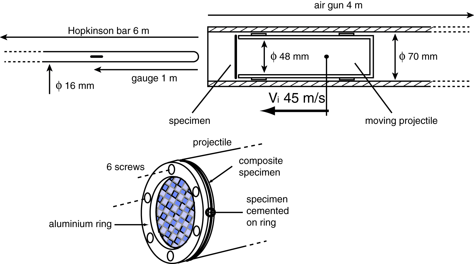
For this first series of dynamic perforation tests, the disc specimen and its support were used as a projectile giving the name of ‘inversed’ perforation experiment since the perforator was initially at rest. In this case, the inner diameter of the gun barrel (ϕ70 mm) used to launch the projectile imposed to limit the diameter of the tested disc of the material. The projectile weighed 750 g and was launched at 45 m/s (as introduced in Zhao et al. 12 ). For the measurement of perforation force, the perforator was a long Hopkinson bar (marval steel, diameter 16 mm, length 6 m) initially at rest (Figure 1). Technically, after a penetration of around 50 mm (after complete perforation of the shell), the projectile momentum was absorbed on a fixed frame (not depicted on the figure).
Quasi-static perforation experiments were performed on a hydraulic machine MTS at a prescribed perforation velocity of 0.1 mm/s. In order to allow a direct comparison of results at low and high strain rates, the projectile of the dynamic tests was used as a support for the quasi-static tests so that the fixation of the specimen was strictly identical. The perforator (a short rod of marval of diameter ϕ16 mm having a hemispherical tip) was clamped in grips that transmitted the perforation force to a load cell MTS of capacity 50 kN.
In our system, the Hopkinson bar allows the measurement of the histories of perforation force F and displacement U during the whole perforation process with a good accuracy: force is directly deduced from the measurement of strain on the bar. Gages are located at a distance of 1.5 m of the tip of the perforator and connected to an amplification system. The displacement of the tip of the perforator is integrated using the velocity obtained from the Hopkinson bar measurement and the velocity of the projectile is calculated under the assumption of force equilibrium in the specimen (Equation 1):

Image recording procedure
Complementary perforation experiments were performed in order to get more details about the perforation process. For these tests, images of the specimen surface were recorded during both static and dynamic tests. These tests were performed in the configuration ‘PP’, which means that the perforator was in contact with the face of the specimen covered with the PP sheet.
For static experiments, by using a specific frame, it was convenient to observe the outer surface of the specimen while the inner surface was in contact with the perforator. The support was changed. The specimen cemented on the aluminum ring was then clamped on a large plate fixed on the columns of the machine. This plate exhibited a circular hole (ϕ50 mm) so that the specimen could be perforated and observed simultaneously. A Pixelfly digital camera was used: images were of resolution 1280 × 1024 pixels 2 and frame rate was 0.25 fps.
For dynamic experiments, it was impossible to obtain both images of the back surface of the specimen and force measurement at the same time. Therefore, in order to acquire images of the perforation, the apparatus was slightly modified so that the specimen was held on a rigid frame located close to the output of the air gun (Figure 2). In this case, the perforator was fixed on the projectile for a direct perforation test. The Hopkinson bar measurement was not available anymore and each experiment was then dedicated to image analysis only. Since these specific imaging experiments were conducted in order to follow the fracture process, the frame rate was increased to 75000 fps and image resolution 128 × 112 pixels
2
focused on the region under the perforator.
Experimental set-up used for imaging the back surface during dynamic perforation.
The direct tension test at 2 m/s
Additional experiments were conducted, for which the material was loaded in pure tension in the direction of the yarns. Obviously for these tests, it is no longer possible to investigate the effect of the PP sheet layer. Fracture stresses were identified on specific geometries of specimen in order to induce cracking in a cross-section far from clamping (geometries are depicted in Figure 3). For static tests, the minimal width was 20 mm. For dynamic experiments, it was necessary to decrease this dimension in order to reach fracture at a prescribed velocity of 2 m/s. The minimal width was then 10 mm and only two yarns were loaded in the smallest cross-section, considered as a minimum for the representativeness of the tested volume.
Specimens for identification of fracture stress and mechanical response in the weft direction.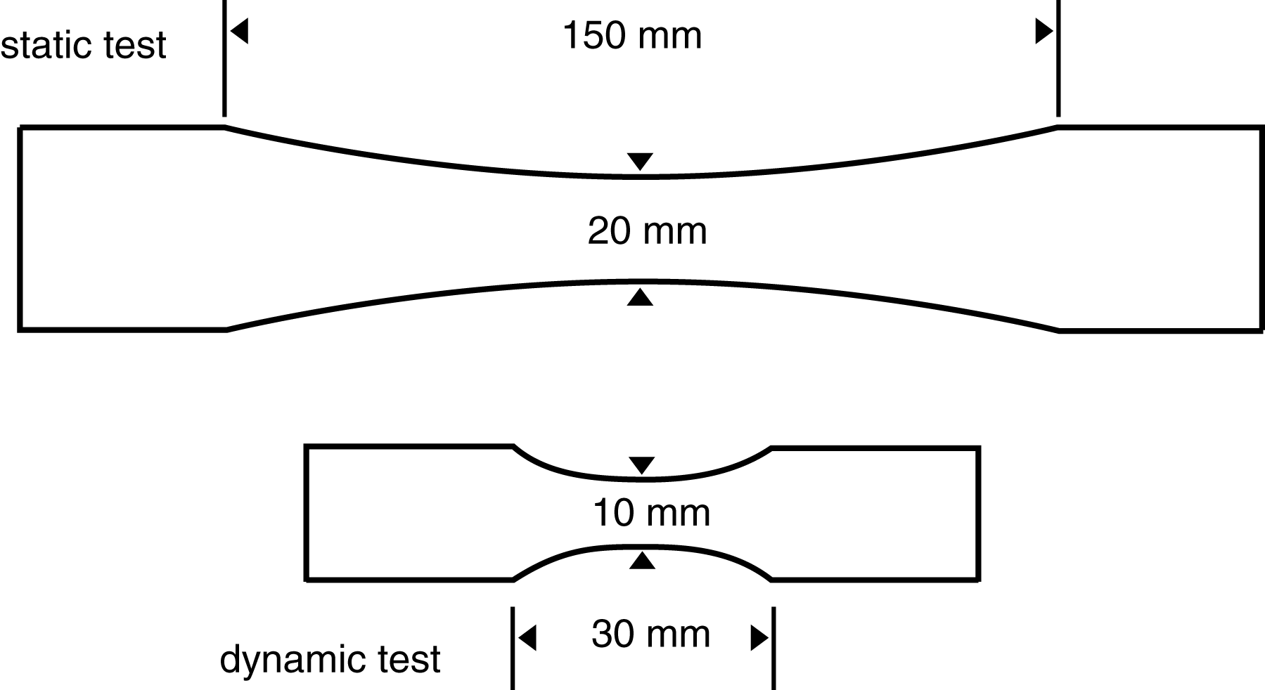
For static tests, a MTS hydraulic machine was used, with a MTS load cell of capacity 5 kN. For clamping, the specimen was glued with Araldite on aluminum end tabs.
For dynamic tests, the tensile experiments were performed with a Hopkinson bar device made of marval steel bars (ϕ10 mm), based on the technology of prestressed bars. 17 The specimen was glued with Araldite on a specific steel end tab having the same acoustic impedance of the bars, and screwed directly on the bars. The extension rate of the specimen was around 2 m/s.
In order to increase the reliability of the test, a high-speed camera was used to obtain a direct measurement of extension and prescribed extension rate from digital image correlation analysis. 18 Frame rate was 63000 fps and resolution of the image 384 × 80 pixels 2 so that the physical size of the pixel was 0.14 mm/pixel. Extension was directly measured from digital image correlation and synchronized with force measurement in order to plot the curves.
Results
This section gives all the results of the experiments that were conducted, and the analysis is presented in detail in the ‘Discussion’ section.
Static perforation
Results of static perforation experiments are given as force–displacement curves in Figure 4. The two configurations, depending on which face (PP sheet or weave) the perforator is in contact, are investigated. It is first observed that for each test, the amount of energy dissipated after the peak is about 20% of the total energy. The observation of the fractured specimen shows several cracks in the area under the perforator.
Perforation curves for static experiments and post-mortem observation.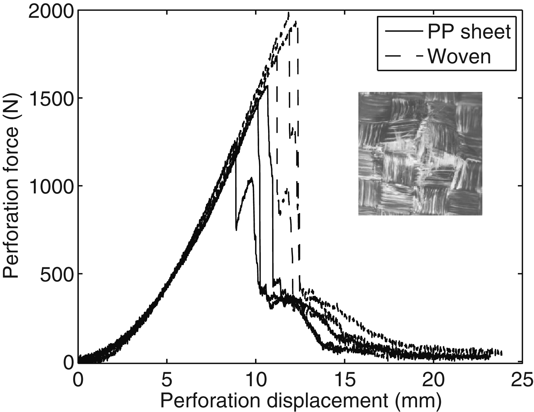
Dynamic perforation
The dynamic curves are plotted in Figure 5. Contrary to the static experiments, the loading exhibits a bilinear increase. This is the signature of the dynamics of propagation of the flexural waves in the shell. Until a displacement up to 7 mm, the flexural wave propagates from the center (contact with perforator) to the edges of the specimen. The reflection at the fixed boundary induces an increase in stress. This can be observed by digital image analysis on the back surface of the specimen, as described in a former paper.
19
Fracture is followed by a decrease of the force before complete perforation. In this dynamic case, the post-peak energy can reach 40% of the total energy dissipated during the whole perforation process. Contrary to static tests, the observation of the area of fracture after testing shows a crater of broken fibers under the perforator.
Perforation curves for dynamic (45 m/s) experiments and post-mortem observation.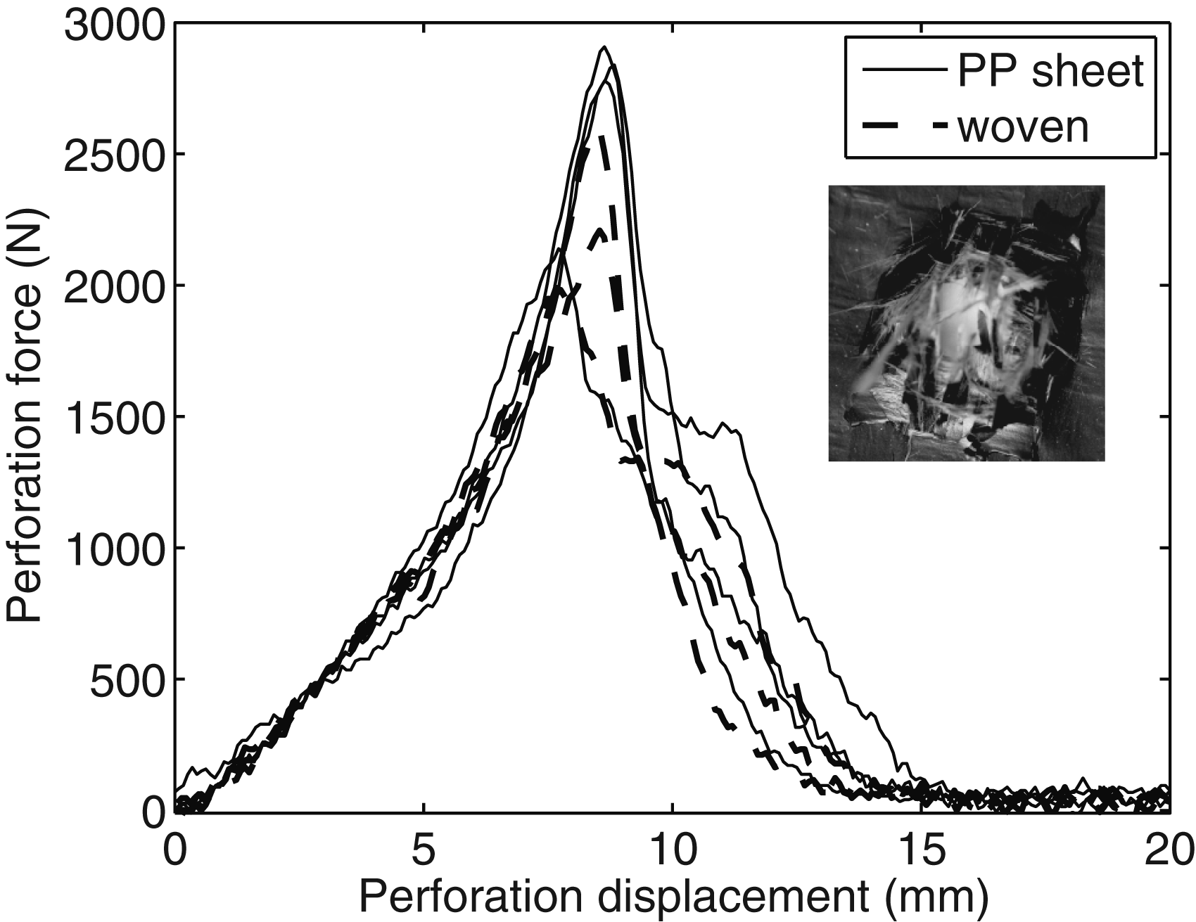
Quantitative results and strain-rate sensitivity during perforation
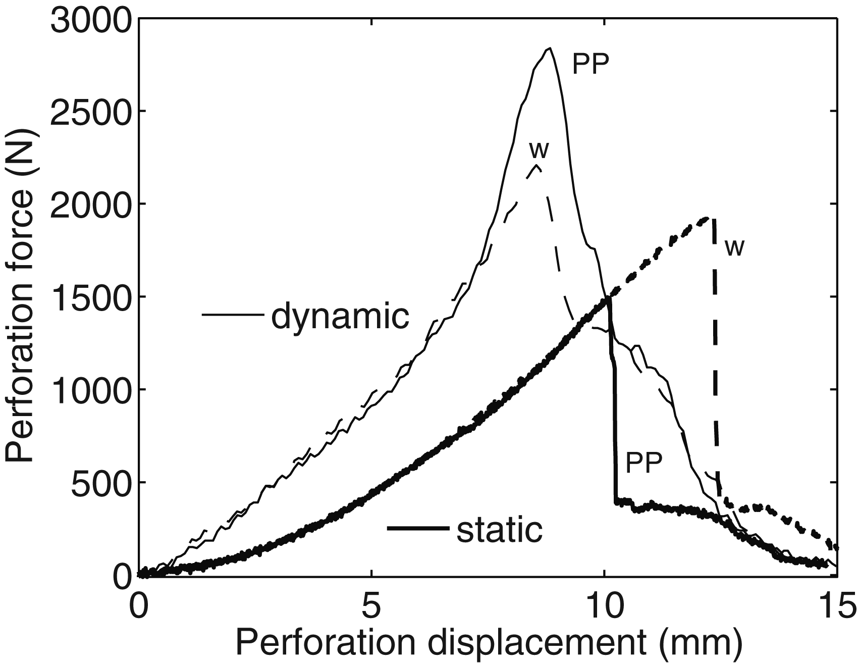
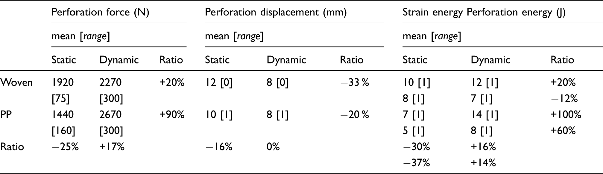
A quantitative comparison of the results of static and dynamic perforation tests is given in Table 1 in terms of mean and standard deviation of the quantities of interest. In Figure 6, a graphical comparison is proposed, using only one result for every group of tests for the sake of clarity. The results about the effect of the perforator velocity and the impact side on the specimen (called PP or weave) are given as follows:
at 45 m/s, there is a significant enhancement of the dynamic perforation force and a decrease of the perforation displacement; moreover, the total strain energy and the perforation energy (at peak load) are increased; and the presence of the PP layer at the contact with the perforator induces dissimilar effect: the perforation force decreases for static loading (and consequently displacement and energy at peak load) while, on the contrary, it increases slightly for impact loading. Moreover, the scatter is much larger for static experiments than for impact tests. Comparison of perforation curves for dynamic (45 m/s) and static experiments. Results of perforation experiments
These results are analyzed in the ‘Discussion’ section.
Results on fracture processes
During static loading, the results show that fracture occurs in successive stages, explained graphically on one example presented in Figure 7. First, a macrocrack nucleates leading to the sudden decrease of the penetration force; then, the shell can exhibit an additional increase in strength when a second crack opens. These macrocracks are located along the interface between the yarns (Figure 4).
Observation of fracture process during static perforation.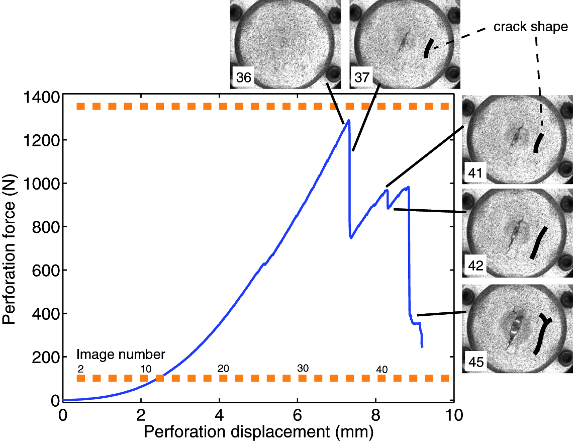
For dynamic experiments, some results about the overall deformation of the shell and the use of digital image correlation to observe the strain field were already published.
19
Here, we focus the analysis on the damaged zone, which happens to be quite different from static perforation because fracture is clearly diffuse (Figure 5) and all the yarns in the area under the perforator are broken. The analysis of one sequence of the images of perforation shows the formation of a multiple nucleation, or fragmentation, as depicted on the images given in Figure 8. The images show that this fragmentation occurs at considerably early moments of the perforation and cannot be attributed to post-peak response or further damage mechanisms.
Fracture process for the dynamic perforation experiment (ca. 15 × 15 mm2, Δt = 13 µs).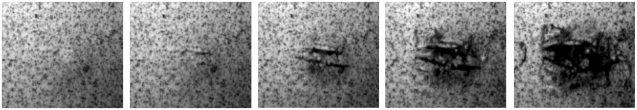
Results on strain-rate sensitivity in pure tension
The results are given in Figure 9 as raw force-extension curves. Extension was measured considering two points located at both ends of the specimen. Fracture stress was calculated by dividing maximum force by the smallest cross-section of the specimen (thickness 0.8 mm and width 20 mm for static or 10 mm for dynamic) where fracture occurred.
Comparison of the mechanical response to static and dynamic uniaxial tension tests performed in the direction of the yarns.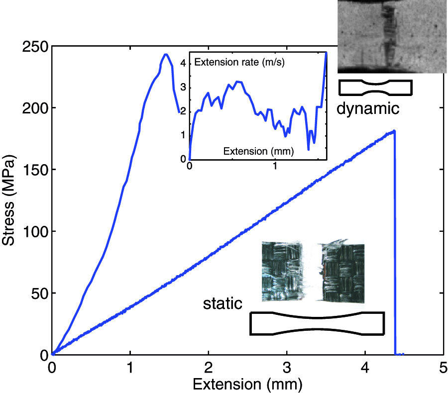
The results show that during static test, fracture is brittle in the directions of the yarns and fracture stress is identified at 180 MPa. For dynamic experiments, fracture stress is identified at 240 MPa, giving a strain-rate sensitivity of ca 30%. Extension rate is not constant during the test, varying between 1 and 3 m/s, and the mean value of 2 m/s is considered. The pictures acquired during the test (not given in this article) show that the macrocrack nucleates from an edge of the specimen and propagates toward the other side in the same way as for static experiments with no change of the fracture process at this velocity.
Discussion
From the results of the mechanical response of the composite material submitted to perforation under high impact velocity (compared to static reference test), two conclusions can be drawn: fracture force increases with strain rate and fracture process under the perforator is different (‘Quantitative results and strain-rate sensitivity during perforation’ section). In the preceding section, it was already mentioned that at 45 m/s, the propagation of flexural waves in the specimen induces an apparent increase in the stiffness. But this cannot explain neither the increase in fracture force nor the decrease in maximum displacement at peak load. Then, in order to go further into the analysis, two mechanical aspects were experimentally investigated: the effect of the strain-rate sensitivity of the constitutive material using direct tension experiments, and the analysis of the fracture process that occur for high impact velocities.
It was expected that the composite material would carry its own strain-rate sensitivity due to the polymer matrix. Regarding fracture, the strain-rate sensitivity of fracture in the direction of the yarns was investigated conducting tension experiments performed at two considerably different strain rates (‘Results on strain-rate sensitivity in pure tension’ section). The results showed that in direct tension up to 2 m/s, the material strength exhibited around 30% of strain-rate sensitivity without any modification of the fracture process. Investigating mechanical response under tension tests at higher extension rates was not possible with such a Hopkinson bar apparatus, and this is a general conclusion for this configuration. This is the reason why it is considered that the perforation test offers a good technical solution in order to measure the mechanical response of materials submitted to tension at high impact velocity, provided that a modeling of the test be handled because direct identification is unfortunately no longer possible.
The complementary experiments performed in order to better understand the difference of fracture process under perforation were conducted using imaging techniques (‘Results on fracture processes’ section). During static loading, the results showed that fracture occurred by successive stages of macrocracking. The energy was therefore dissipated by nucleation-propagation of the cracks, and by friction between the composite material and the perforator. For dynamic experiments, fracture occurred by multiple nucleation of microcracks, analogous to fragmentation, at early stage of the penetration. The contribution of energy dissipation in fracture was therefore increased due to fragmentation of fibers so that damage area was much more extended than for the static case. As already stated by Lee et al., 5 dissipation of energy during perforation can be correlated to the number of yarns being deformed till fracture. We consider the extension of the description considering the amount of fibers being fractured during the perforation of the shell and the energy dissipated through surface creation in the mechanism of fragmentation as a challenging prospects to this study.
Conclusions
Experiments were conducted on a TP composite material in order to measure the strain-rate sensitivity of the perforation force and energy. An inversed perforation experiment based on Hopkinson bars was implemented. The results showed that in a range from 0.1 to 4500 mm/s, fracture force and energy increased in a range from 20% to 100%. It was noticed that the fracture process has changed from nucleation and propagation of macrocracks to fragmentation in the area under the perforator. The experimental analysis of the influence of the presence of a PP-sheet on one side of the specimen was investigated and it led to unexpected and still un-explained dissimilar effects when comparing static and dynamic results.
Classical experiments of tension tests up to 2 m/s showed a strain-rate sensitivity of around 30 % of the material, with no observable modification in the fracture process. The limitation in prescribed velocity of such an experiment did not allow the investigation of the effect of uniaxial dynamic fracture of yarns at impact velocity 45 m/s. Additional experiments were conducted to analyze how the crater observed after impact perforation was created. High-speed observation allowed concluding that fragmentation of the fibers occurred at early stages of the penetration of the perforator and should have a non-negligible contribution to energy dissipation.
Footnotes
Funding
This research received no specific grant from any funding agency in the public, commercial, or not-for-profit sectors.