
Abstract
This article presents a study of large tape springs to be used as ribs of an ultra-thin shell space deployable reflector. The tape spring, both longitudinally and transversely curved, is made of carbon/epoxy composite and subject to two-dimensional or three-dimensional folds. The behaviour of tape springs with different dimensional parameters during folding is investigated by finite element analyses and an analytical approach. Peak moments, steady-state moments and strain levels are obtained for several parameters such as curvatures, length, thickness, subtended angle, etc. The analytical approach considers the bending strain energy during two-dimensional folding of the tape spring, and it does not capture the full behaviour due to the assumptions made for the simple solution. The results obtained by the two methods are compared where they are applicable and are in agreement for the tape springs subject to two-dimensional folds. Feasibility of the curved large tape springs as a rib-reinforcing element for the deployable reflector with 6 m diameter is investigated. A breadboard model of 90 cm diameter is manufactured and tested for packaging and deployment behaviour.
Introduction
Assuring structural integrity of reflectors is considerably important for safe space constructs. For the reflectors to be compactly foldable and deployable, they require various fasteners or a mechanism. It is of utmost importance that these elements be light and sufficiently rigid. It is aimed that the reflector should be fully deployable after folding. In some of these reflectors, elastic energy is stored during folding and then used for the deployment of the reflector; whereas in some others, additional power is required for deployment. Composite tape springs, slotted or perforated tubes and deployable hinges are used for self-deployable fasteners.
Tape springs are thin strips with a curved cross section. They have been used as deployment hinge or reinforcing elements of deployable space structures. Key feature is that the tape spring is folded elastically and then deployed by the stored elastic energy without the need of any deployment devices.1,2 The tape springs are classified into two types: (a) initially straight and (b) initially curved. The initially straight one is most commonly used, known as carpenter tape, which has only a transverse curvature. The straight tape spring is widely used as a hinge for some space applications such as solar array, boom, truss, etc., and also as a reinforcing element for singly curved structures.3,4 The initially curved tape springs have both longitudinal and transverse curvatures and are used as reinforcing element of doubly curved space structures (Figure 1). There are a number of analytical and numerical studies for the folding and deployment behaviour of the straight tape springs.5,6 These studies focused mostly on two-dimensional (2-D) fold; however, there are relatively less studies on 3-D fold.
7
On the other hand, much less studies on the curved tape springs have been performed.
2
Geometric properties and 2-D folding of an initialy straight tape spring.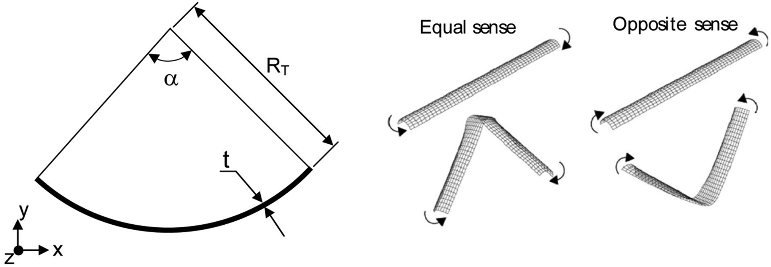
In early studies, Seffen et al. 2 and Seffen and Pellegrino 8 analysed folding and deployment behaviours of doubly curved elastic tape springs. The tape springs were used to support reflective membrane surfaces and were tested for compactly folding and deployment behaviour of these structures. The results obtained by different analytical approaches, experiments and finite element methods (FEMs) were compared. Dynamic deployment analyses of a compact model were conducted for zigzag folding and circular wrapping around the centre. Shape changes occurring in both types of packaging were analysed. Moreover, Pellegrino 9 built a small-scale deployable rib tensioned membrane reflector with 1.5 m diameter, performed folding and deployment tests and calculated root mean square errors for the full-scale model. Walker and Aglietti 7 studied the static moments of tape springs created during 3-D equal-sense fold, and applied them to a simple dynamic model of an array. It was found that the deployment energy was significantly reduced when compared to the 2-D fold. Later, Walker and Aglietti 4 analysed the bending-moment behaviour of deployable curved tape spring with a photographic method. They determined the areas where the length of the tape spring became critical by analysing curvature-moment levels of 2-D and 3-D curved tape springs. It was found that the length of the tape spring was critical due to twist and affected the curvature of the fold and hence the opening moment of the folded tape spring. Constant curvature assumption was suggested for the 3-D deployment moment of the post-buckled tape spring.
Tape springs are also used to make elastic hinges of deployable space structures such as boom, truss, solar panel, space telescope, etc. A study on deployment repeatability of a composite hinge was conducted by Domber et al. 10 The hinge was an integral part of a cylindrical tube and was obtained by geometry variation. The authors experimentally analysed the deployment repeatability of this cylindrical structure and evaluated permanent deformations that occurred on the tube after folding. No significant permanent deformations were observed. Stowage time increased the viscoelastic creep, but it was recovered. Recently, Soykasap 1 analysed the static moment vs rotation behaviour of tape spring hinges subject to 2-D and 3-D folds analytically, experimentally and by FEM. The hinges consisted of pairs of hardened steel tape springs mounted side by side in different configurations. The best configuration was obtained for compact volume in folded configuration and was provided for positive moment of deployment. More recently, Soykasap 11 studied deployment analysis of a self-deployable composite boom. Rotation-moment behaviour of a thin-walled elastic cylindrical structure made of a combination of three classical elastic tape springs was analysed in the course of folding and deployment by non-linear FEM. Moreover, an analytical approach was also suggested for the deployment of this structure and the alignment of this approach with the experimental study was also established. Most recently, Hoffait et al. 12 studied the dynamic behaviour of the tape spring hinges by dynamic FE analyses. The hinge consisted of three tape springs mounted side by side. The study was focused on the self-locking phenomenon, which was strongly affected by 3-D hinge kinematics and torsional deformation of the tape springs.
In this article, folding behaviour of large curved tape springs to be used as ribs of space deployable reflector is studied by FEM and an analytical approach. In the following section, the folding behaviour of tape springs with different dimensional parameters is investigated by FEM analyses and analytical approach. The curved tape spring is made of triaxialy woven carbon/epoxy composite and subject to 2-D or 3-D folds. The curved tape springs are modelled in Abaqus FEM program, 13 and non-linear static analyses are carried out for both 2-D and 3-D folds; whereas, an analytical approach is used for only 2-D folds. Peak moments, steady-state moments and strain levels are obtained for several parameters such as initial curvatures, length, thickness, subtended angle, etc. The subsequent section is devoted to feasibility study of the curved large tape springs as a rib-reinforcing element for the deployable reflector. A breadboard model of 90 cm diameter is manufactured and tested for packaging and deployment behaviour. Finally, concluding remarks are given in the last section.
Static analysis of curved tape spring
Structures to be designed for spacecraft are required to be of low cost, light, non-complex, and packable. Structures in which electric motors and small mechanisms are used increase the complexity, costs and weight considerably. 4 Therefore, researchers have suggested flexible and elastic tape springs which can store energy for foldable and deployable space structures. The tape springs can be folded either in the sense opposite to the initial transverse curvature or in the same sense and are subject to 2-D or 3-D folds depending on the application. A 2-D fold is formed when the fold line is perpendicular to the longitudinal axis of the tape spring, resulting in longitudinal bending; whereas, a 3-D fold is formed when the fold line is not perpendicular, resulting in both longitudinal bending and twisting.
In 2-D fold, an initially straight tape spring has positive or negative bending moments depending on the direction of the applied moments or rotations. These are called opposite-sense and equal-sense bending moments, respectively, which appears during folding and deployment. Shapes of the tape spring before and after folding, directions of loading along with its general geometric properties are given in Figure 1. Here, α denotes the subtended angle of cross section, RT the radius of the curved cross section and t the thickness of the tape spring. Schematic moment-rotation angle is shown in Figure 2. 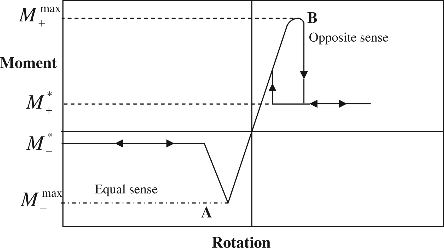
Curved tape spring has both initial longitudinal and transverse curvatures. The elastic tape springs considered have two configurations of A and B, as observed in Figure 3. The configuration A has a positive Gaussian curvature whereas the configuration B a negative one. Here, RL is the initial longitudinal radius curvature; RT the initial transverse radius of curvature; α the angle subtended by cross section; and L the projection length of the tape spring.
Initial curved tape spring, configuration A (bottom) and B (top).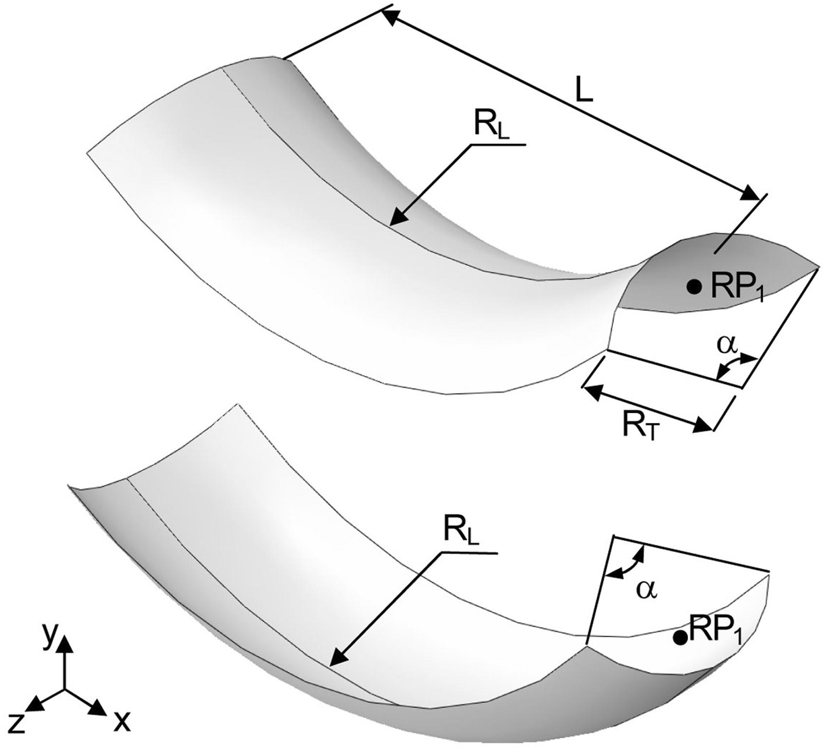
2-D folding analysis by analytical approach and FEM
2-D folding analysis can be carried out by analytical approach based on thin shell theory in order to obtain the behaviour of the tape spring such as the peak moments, the steady moments and fold radius in the early design phase. Although the steady moments and the fold radius can be accurately obtained for certain tape springs, the peak moments might not be accurate.2,8 Therefore, the full folding behaviour of the tape spring is then obtained accurately by non-linear FEM.
Seffen et al.
2
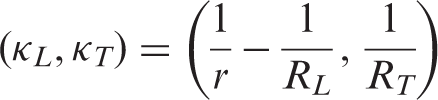
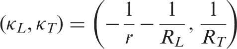
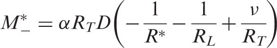
give an analytical approach to calculate the approximate values of the steady moments and the fold radius of the curved tape springs based on thin shell theory. Ignoring the stretching energy in folded configuration and considering the bending energy of the tape spring, the equations obtained are summarized. Bending strain energy occurring in the unit area of a thin isotropic shell is calculated as follows
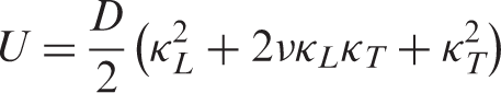
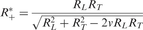
The similar calculations can be done for equal-sense bending as well. However, the fold radius in equal-sense bending is the same as for the opposite-sense one

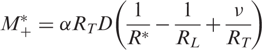
Bending moment after folding is calculated by multiplying arc length of the cross section, flexural rigidity and curvature changes in the cross section. The steady-state moments for opposite-sense and equal-sense bending are obtained as follows.
For a more accurate folding analysis, the curved tape spring is modelled in Abaqus FEM program. 13 Equal and opposite rotation angle, θ, about z-axis is applied for both configurations at reference points RP1 and RP2, which are defined at the cross-sectional centroid of the ends. All the nodes at either end are connected to the corresponding reference points by multi-point constraints. The boundary conditions and prescribed rotations are then applied to RP1 and RP2. Translation degrees of freedoms of Ux and Uy are left free whereas Uz is fixed. In terms of rotational degrees of freedom, URx and URy are fixed and URz is given a rotation of 90° at RP1 and −90° at RP2. It is assumed for all 2-D and 3-D folding analyses that the same material is going to be used for all models. The tape springs are made of SK-802 triaxial carbon fibre/epoxy, which has an quasi-isotropic behaviour with an elastic modulus of 30 GPa, Poisson’s ratio 0.5 and density 980 kg/m3. 14 The model is then meshed with a mesh size of 5 mm using general purpose thin or thick shell quadrilateral elements (S4R). The geometrically non-linear static analyses are performed to simulate the folding behaviour. Damping factor for stabilization is determined to be 10−7 in order to have a converged solution.
Comparison of analytical approach and FEM (L = 2.5 m, RT = 0.3 m, t = 2 mm)
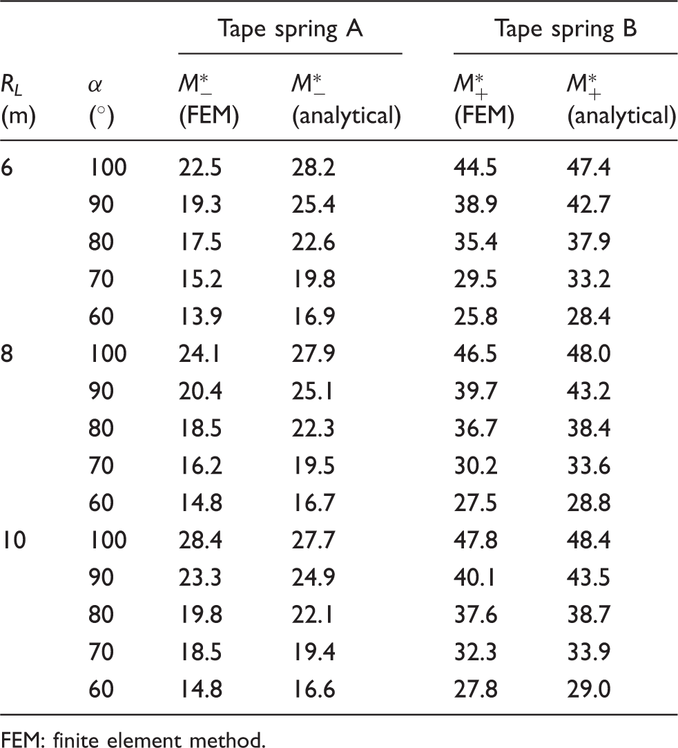
FEM: finite element method.
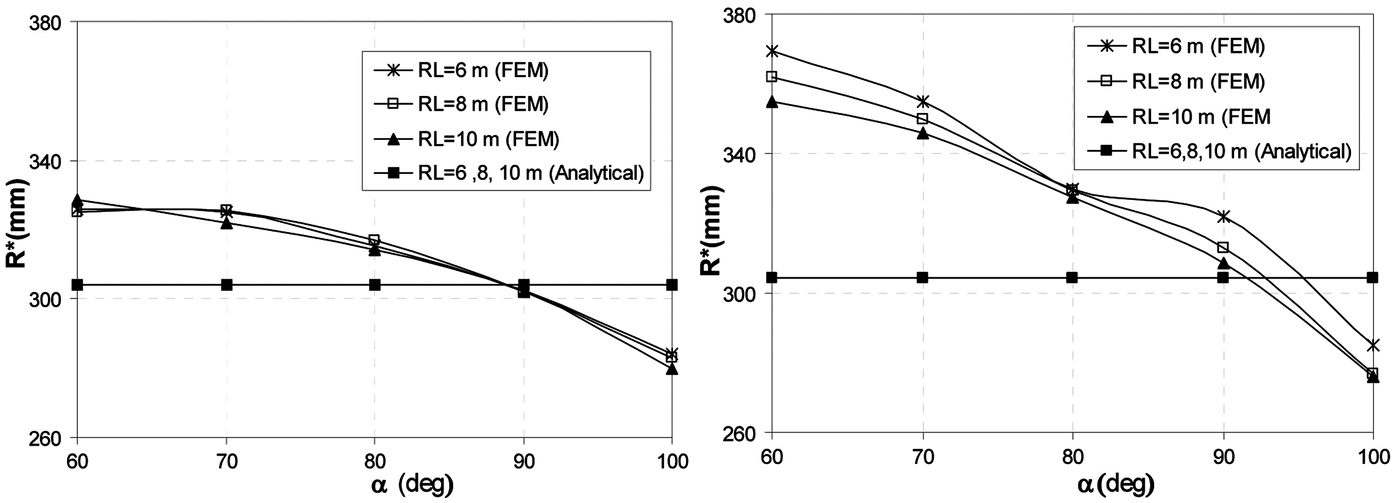
In Figure 4, the fold radius R* vs the subtended angle α is given for the tape springs A and B with different values of RL. According to FEM results, R* depends on α, it is always higher in tape spring B. R* decreases with increasing α for both tape spring configurations. This decrease is smaller in tape spring A than B. When α is at its largest value of 100°, the fold radius is approximately the same for both configurations. On the other hand, R* does not depend on α, nor on the direction of loading, and is almost constant for RL values according to the analytical approach (equation (4)). According to the analytical approach, R* is 302.4 mm for RL = 6 m, whereas R* is 304.5 mm for RL = 10 m.
Fold radius R* vs subtended angle, tape spring A (left) and B (right) (L = 2.5 m, RT = 0.3, t = 2 mm).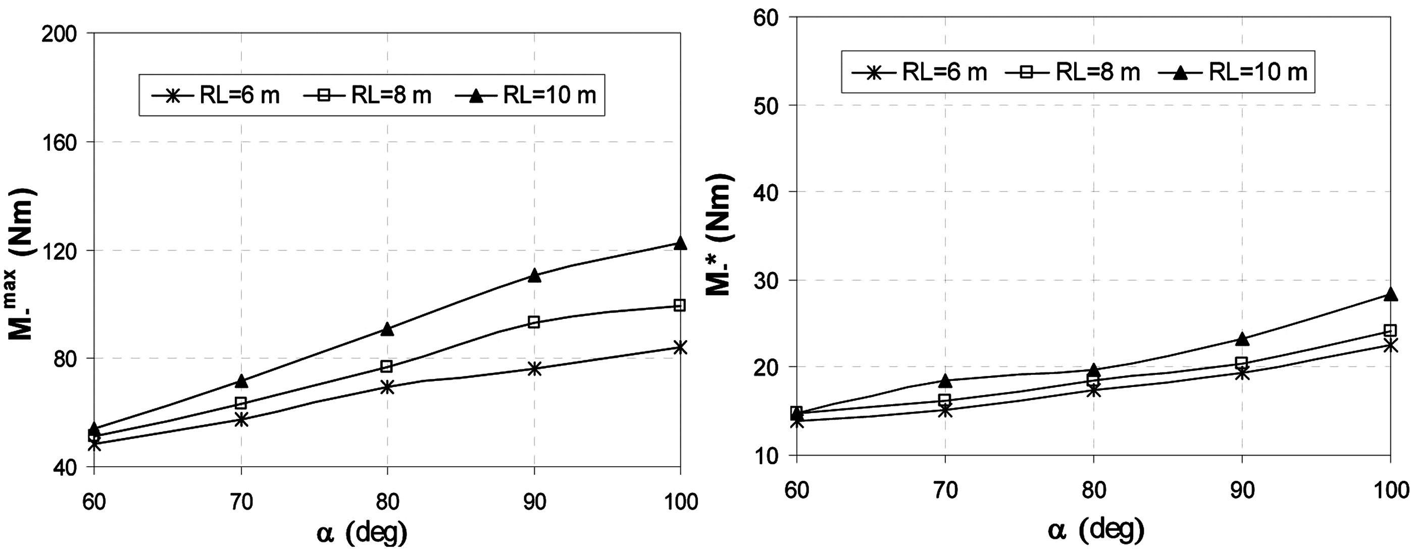
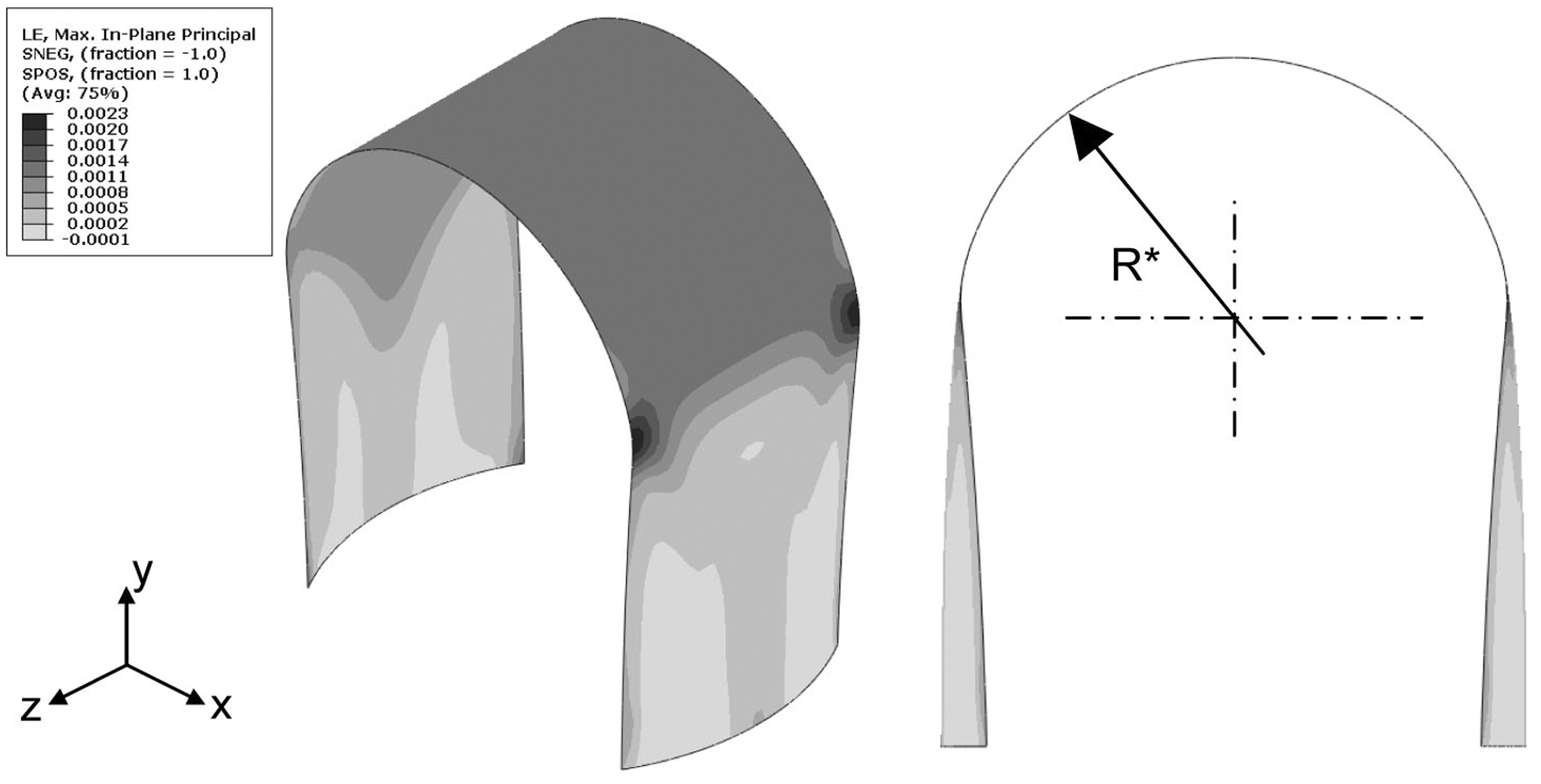
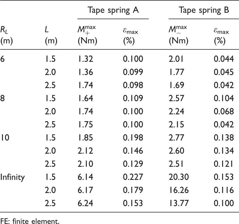
Two tape springs (configurations A and B) with initial thickness t = 0.6 mm, transverse radius RT = 300 mm, and α = 60° were analysed by FEM. Moments and strains of the tape springs with different initial longitudinal curvatures and different lengths are obtained and given in Table 2. For each tape spring with different values of RL, the peak moments decrease by increasing L. Moreover, as initial curvature increases, peak moments also increase. Especially, there is a great difference between the straight and curved tape springs in terms of the peak moments. The maximum logarithmic strains in tape spring A are greater than those of tape spring B. The size of this difference in strains increases as the radius of curvature decreases. In Figures 5 and 6, the changes in the peak moments and the steady-state moments of the tape springs A and B are given for different α and RL, respectively. At small α, the tape springs with different values of RL have approximately the same peak moments for both configurations. As α increases, the peak and steady-state moments increase for both configurations. The slope of this increase in moment-subtended angle graph is smaller in tape spring A than that of B. This condition holds for the steady-state moments as well. In Figure 7, the in-plane logarithmic principal strains are given for tape spring A after folding. The folded tape spring has a single curvature in the mid-region, which deforms to a cylindrical form with radius R*. Maximum strains occur in the transition region from the singly curved region to doubly curved one near the edges.
Peak and steady-state moments vs subtended angle for tape spring A (L = 2.5 m, t = 2 mm, RT = 0.3 m). Peak and steady-state moments vs subtended angle for tape spring B (L = 2.5 m, t = 2 mm, RT = 0.3 m). Contour of principal strains of tape spring A (RL = 6 m, RT = 0.3 m, L = 2.5 m, t = 2 mm, α = 100°). FE results of curved tape springs, 2-D fold (RT = 0.3 m, t = 0.6 mm, α = 60°) FE: finite element.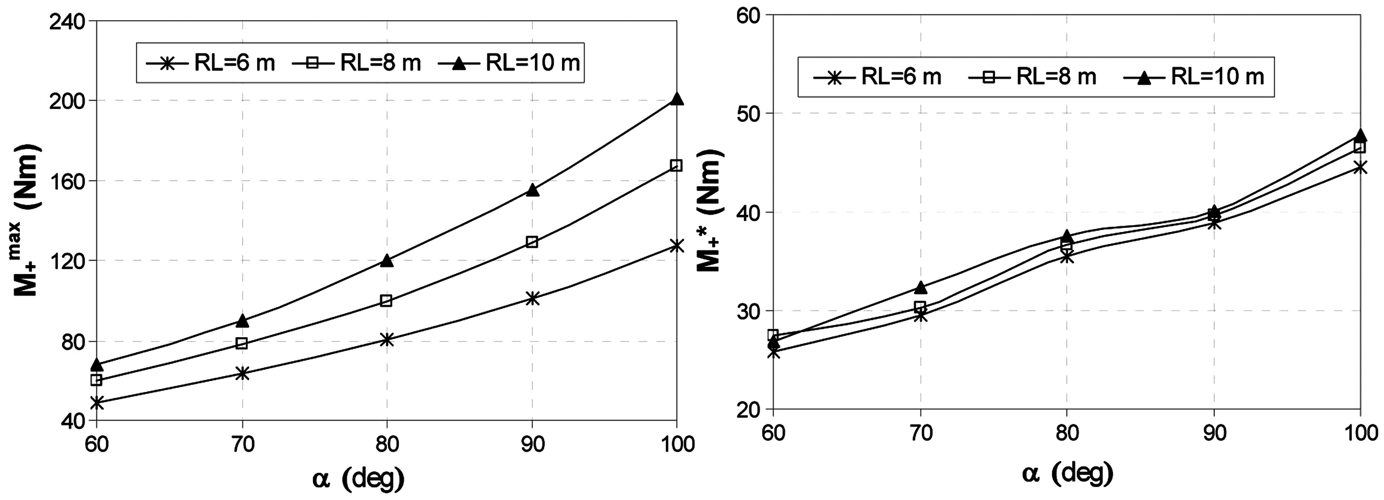
FE analysis of 3-D folding
Putting doubly curved elastic tape springs on the back of a reflective surface as support element, these elements will symmetrically and radially encircle the parabolic reflector. In that case, some tape springs will be subject to 2-D bending where the fold line of the reflector is 90° (or 3-D fold angle of ϕ = 0°) from the longitudinal axis of the tape spring. However, the others will be subject to 3-D bending where the angle between the fold line and the longitudinal axis is less than 90° (non-zero angles of ϕ), as observed in Figure 8. In this study, the peak and twisting moments on the tape spring are analysed at different 3-D bending angles. In Figure 8, an elastic tape spring with a 3-D fold angle of ϕ = 45° is given.
3-D folding of tape spring (ϕ = 45°).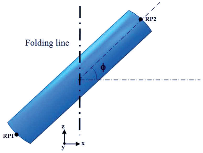
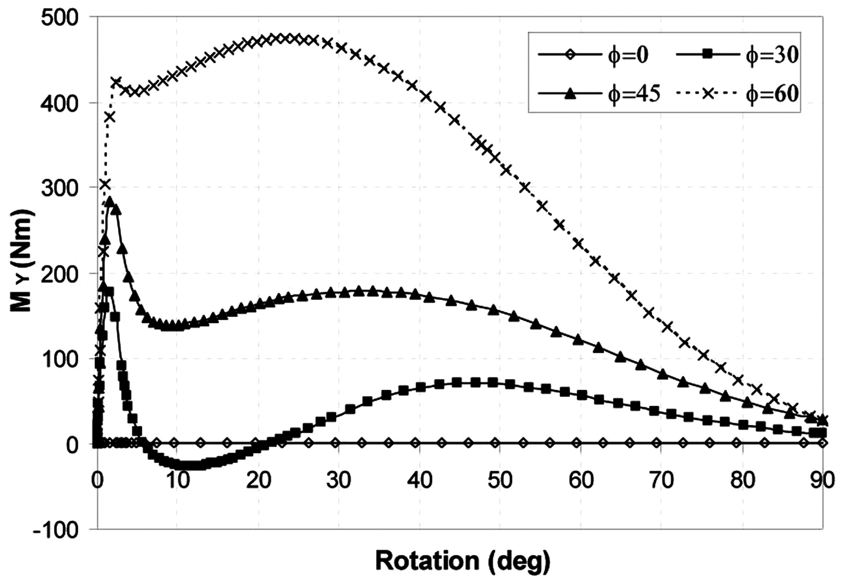
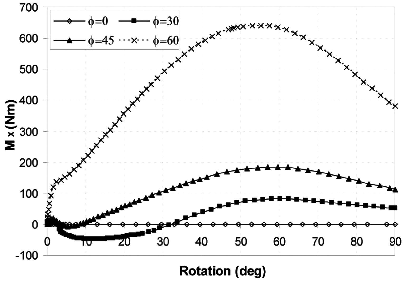
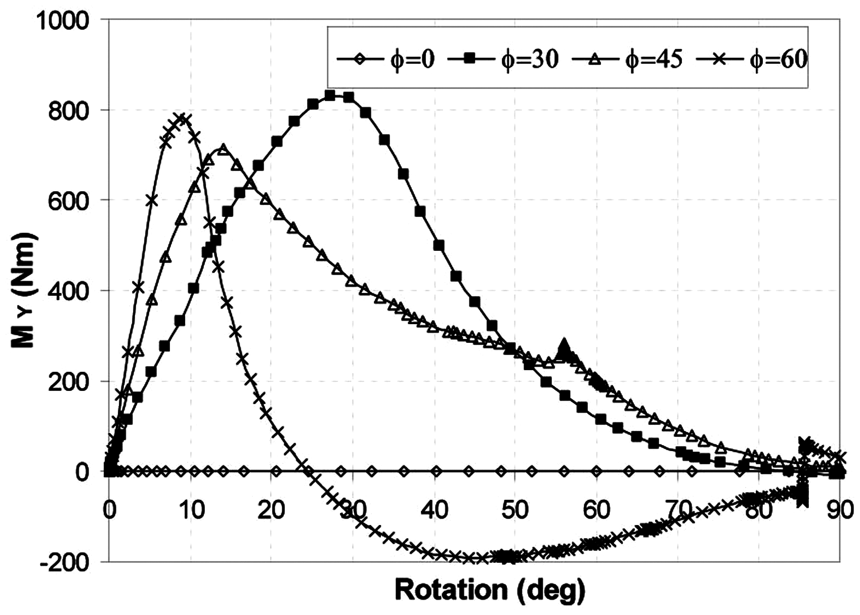
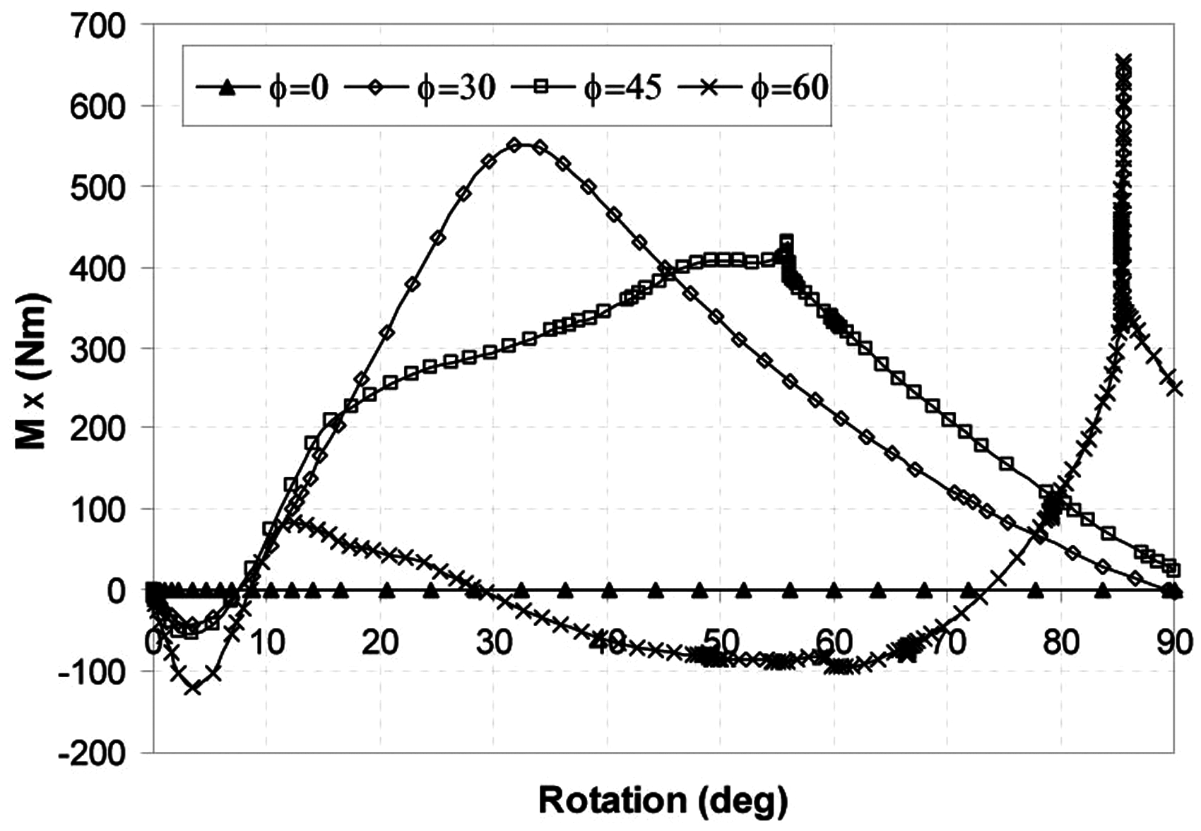
The results of tape spring A are obtained for different ϕ and are given in Figures 9 to 11 for the reaction moments of Mz, My and Mx, respectively. As it can be observed from Figure 9, the peak-bending moment Mz is obtained at ϕ = 0° (i.e. 2-D fold), and it decreases as ϕ increases; whereas, the steady-state moments are approximately the same. As seen from Figures 10 and 11, significant reaction moments occur about x- and y-axes due to a combination of bending and twisting effects of the tape spring. My reaches a peak and decreases soon after the buckling of the tape spring, whereas Mx tends to increase to a relatively high steady moment. It is interesting to note that My and Mx become negative for ϕ = 30° during folding because the localized lateral and torsional buckling occurs and the tape spring snaps through a different state of deformation. Therefore, the tape springs subject to higher 3-D fold angles are not recommended for use as a rib of foldable shell reflectors, the effect of which should be investigated further.
Mz vs rotation for different 3-D fold angles, tape spring A (RL = 6 m, RT = 0.3 m, L = 2.5, t = 2 mm, α = 100°). My vs rotation for different 3-D fold angles, tape spring A (RL = 6 m, RT = 0.3 m, L = 2.5, t = 2 mm, α = 100°). Mx vs rotation for different 3-D fold angles, tape spring A (RL = 6 m, RT = 0.3 m, L = 2.5, t = 2 mm, α = 100°).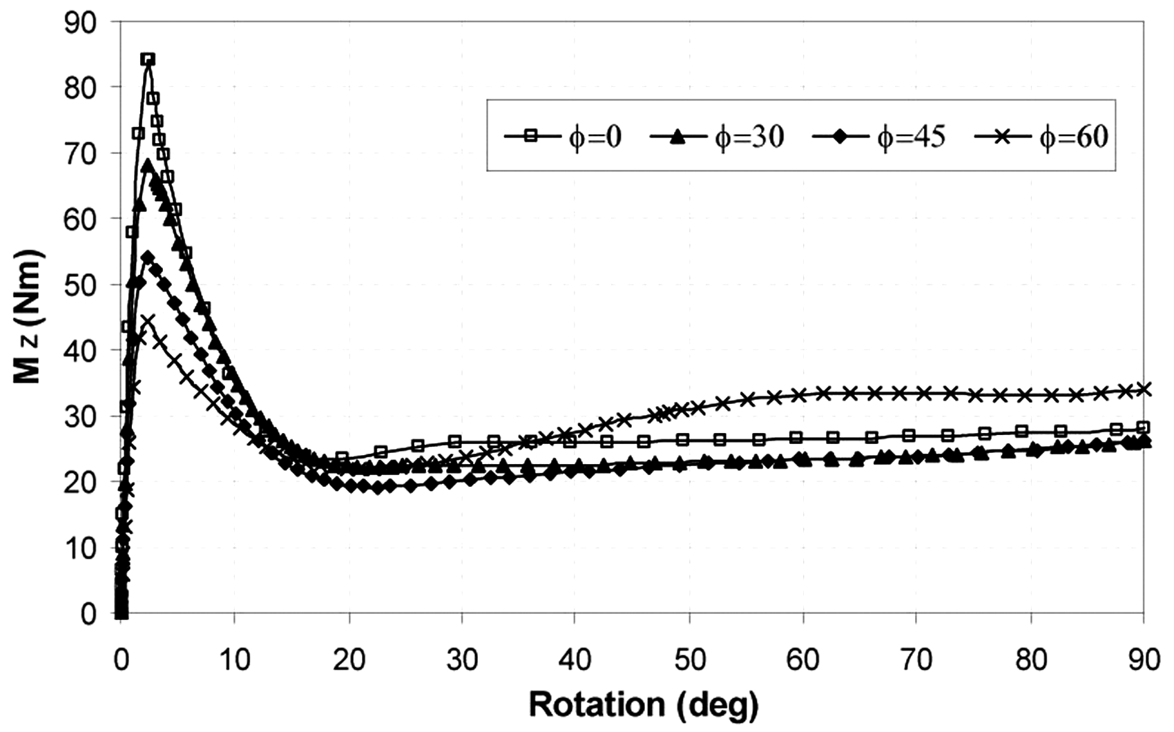
Similarly, the results are obtained for different values of ϕ of tape spring B and are shown in Figures 12 to 14 for the reaction moments of Mz, My and Mx, respectively. Peak moment of Mz is higher than that of the tape spring A. The steady moments are almost constant for lower ϕ, whereas they tend to increase for higher ϕ· As observed from Figures 13 and 14, the moments My and Mx, are higher even for low ϕ than those of the tape spring A. Therefore, the use of the tape spring A as a rib seems to be superior to B.
Mz vs rotation for different 3-D fold angles, tape spring B (RL = 6 m, RT = 0.3 m L = 2.5, t = 2 mm, α = 100°). My vs rotation for different 3-D fold angles, tape spring B (RL = 6 m, RT = 0.3 m L = 2.5, t = 2 mm, α = 100°). Mx vs rotation for different 3-D fold angles, tape spring B (RL = 6 m, RT = 0.3 m L = 2.5, t = 2 mm, α = 100°).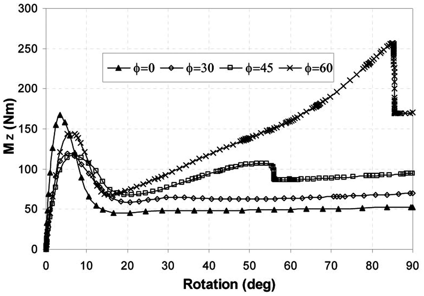
The contours of the principal logarithmic strains in folded configuration are given in Figure 15 for both tape springs A and B. The maximum strain is 0.7% for tape spring A and 1.1% for B, in which the tape springs have the same parameters.
The contours of logarithmic strain of 3-D folded tape spring A (left) and B (right) (RL = 10 m, RT = 0.3 m, L = 2.5, t = 2 mm, α = 100°, ϕ = 45°).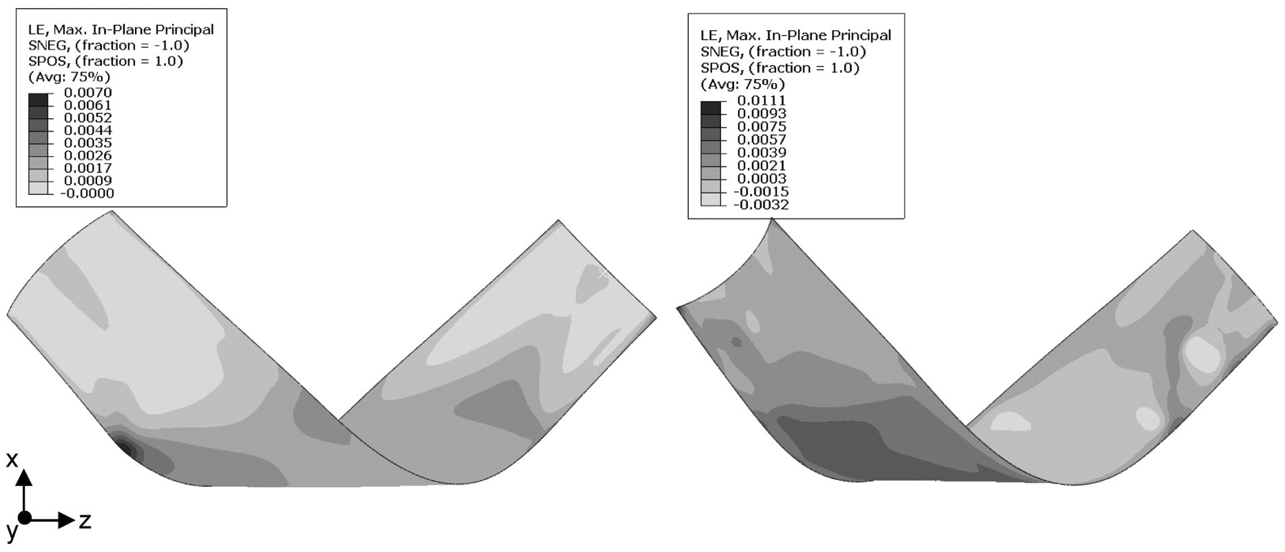
Tape spring reinforced thin shell reflector
In this section, feasibility of the curved large tape springs as a rib-reinforcing element of a deployable reflector is investigated by FEM analysis. Design parameters of the reflector are as follows: the diameter of the parabolic reflector is 6 m and the focal length F = 4.8 m. Reflective surface of the reflector is a thin parabolic shell made of composite material. The surface is supported by curved tape springs of configuration A or B, which are attached to the back of the reflector surface. The tape springs are subject to opposite-sense bending in configuration B whereas to equal-sense bending in configuration A. Main requirements of the reflector are its stiffness in deployed configuration and its mass. 14 It is required that the natural frequency of the reflector be greater than 1 Hz and its mass less than 1.5 kg/m2.
Reflector models supported by opposite-sense or equal-sense bending elastic ribs
In these models, the elastic supports consist of tape spring configurations A or B (Figure 16). Two different models with 8 and 12 ribs of each configuration are considered for the natural frequency analyses of the reinforced reflector. RT is taken to be 0.30 m in the model with 8 ribs whereas 0.15 m in that with 12 ribs. The subtended angle α of all ribs is assumed to be 60°. Ribs are placed evenly at circumferential distances starting from at a diameter of 0.9 m from the centre. RL of the ribs is taken to have the same radial curvature of the reflector surface. The reflector thickness of 0.3 mm is taken to be constant for both models.
Elastic rib supported reflector model with eight ribs: configuration A (left) and B (right).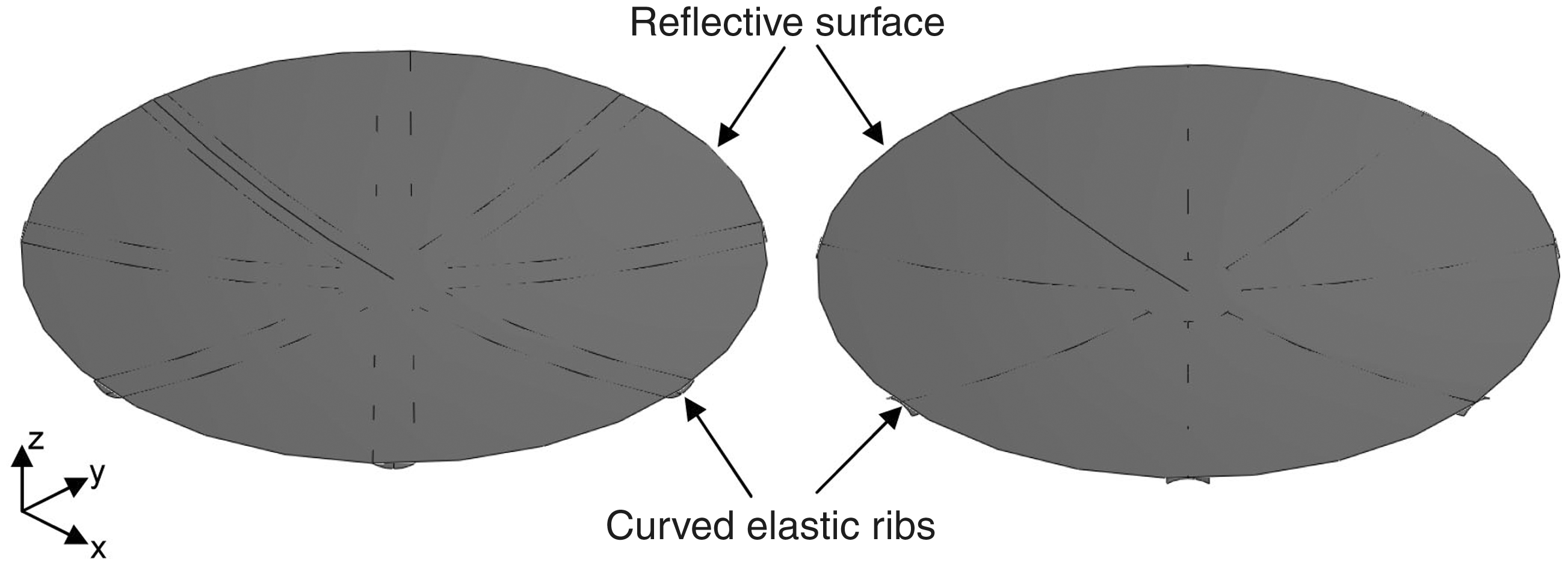
Materials of the reflective surface and the rib are the same, the triaxial carbon fibre/epoxy with quasi-isotropic properties: elastic modulus E = 30 GPa, Poisson’s ratio 0.5 and density 980 kg/m3. The ribs are attached to the reflective surface using tie constraints. Sides of the tape springs are connected to the reflective surface in configuration A, whereas the tape springs are connected tangentially to the reflective surface using the points defined at the middle of the cross section in configuration B. The structure is then meshed with a mesh size of 25 mm. S3 general-purpose triangular elements are used for the reflective surface whereas S4R quadrilateral elements for the ribs. Lanczos solution method is used for the natural frequency analysis.
The fundamental natural frequency is analysed by changing the rib thickness in both models and is given in Figure 17. The natural frequencies increase in both models with increasing rib thickness. The rate of increase is approximately the same for both models. It is concluded that provided the same rib thickness, 12-ribbed model is better than the 8-ribbed one for considering the lower mass and higher frequency for opposite-sense bending elastic ribs. On the other hand, the natural frequency of the reflector with 8 ribs is better than that of the reflector with 12 ribs subject to equal-sense bending. The reflector with the tape springs of configuration A has superior stiffness with almost two times higher natural frequency for the same mass of the reflector with the tape springs of configuration B.
Fundamental natural frequency vs rib thickness, tape spring A (left) and B (right).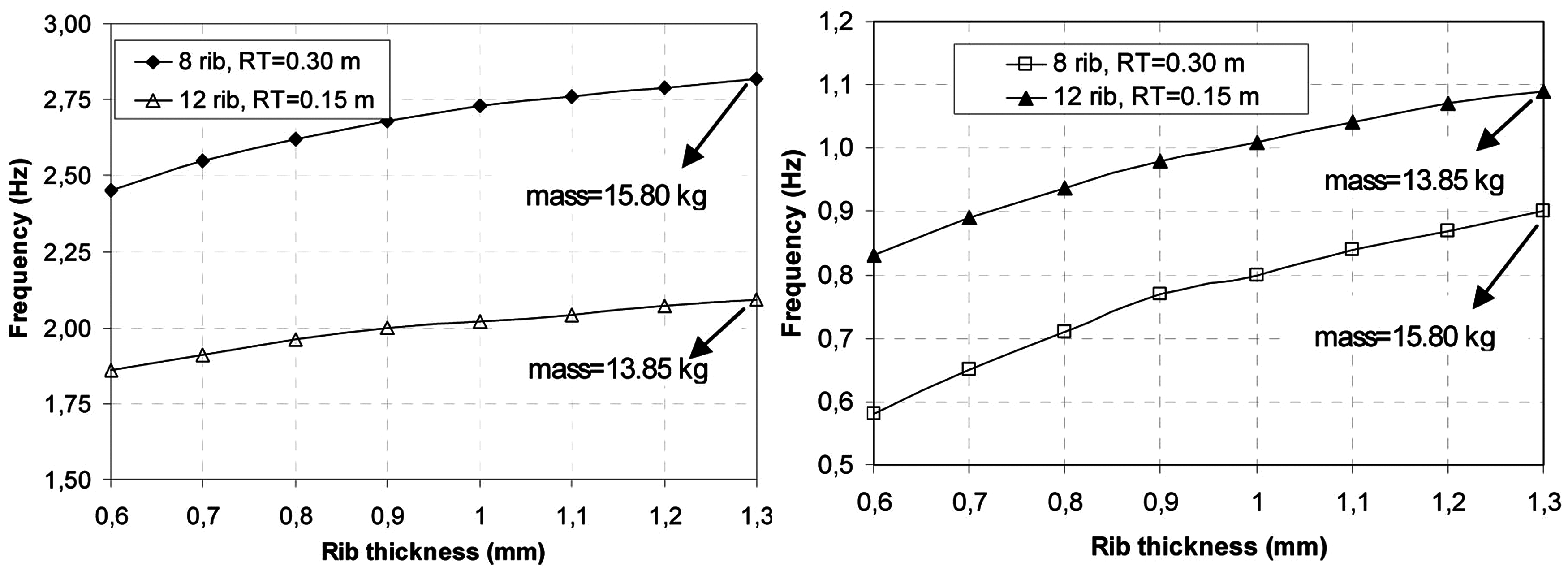
Breadboard model
Having found that configuration A is better, a breadboard model is manufactured and tested for packaging and deployment behaviour. The reflector is an axial fed parabolic antenna; it has a diameter 90 cm and a focal length 50 cm (Figure 18). It is made of plain woven glass/epoxy; the fabric has 0.1 mm thickness, 49 g/m2 areal density and the epoxy is Hexion L160. To provide more rigidity, the reflector surface is assumed to consist of four plies within a diameter of 0.35 m, three plies between the diameter of 0.35 m and 0.7 m, and two plies for the rest, as seen in Figure 19. The ribs consist of five layers of the same material; they have a thickness of 0.55 mm and a subtended angle of 60°, approximately. The reflector surface is supported by eight ribs which radially encircled the parabolic reflector surface with 45°. The ribs are attached to the reflective surface using short lengths of duct tape at radial intervals so that the ribs comply with the folding of reflective surface.
Equal-sense bending elastic rib supported scaled reflector model. Laminating case of reflective surface.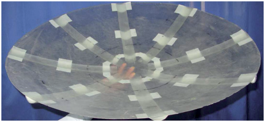
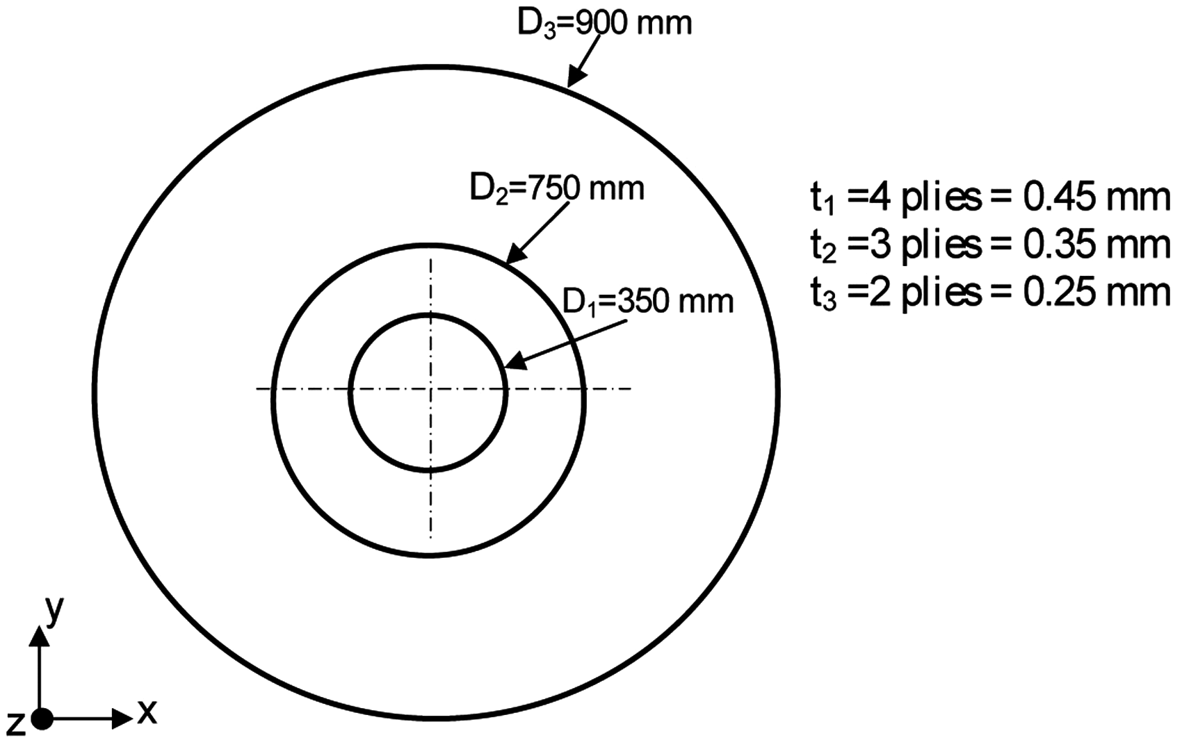
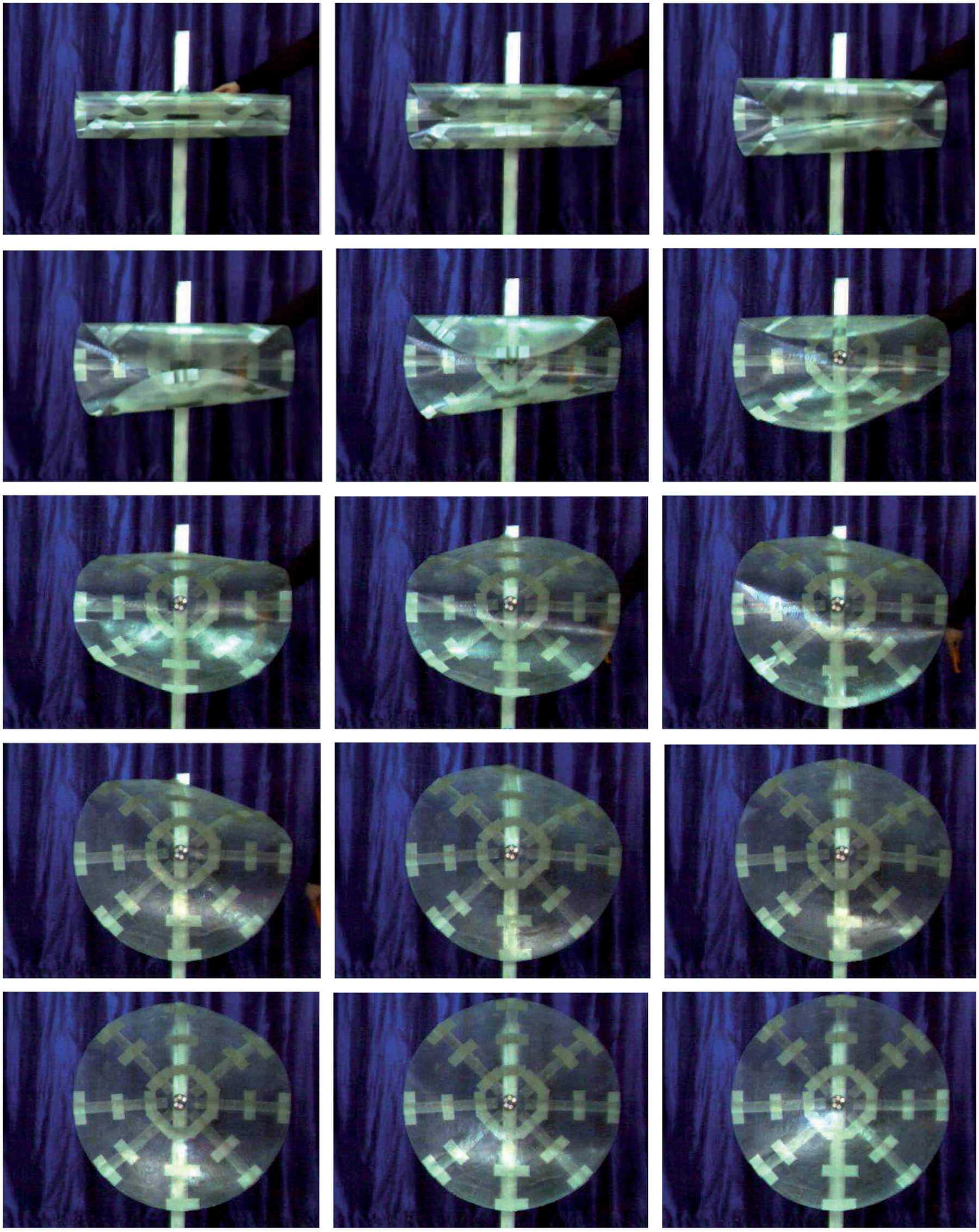
Figure 20 shows the folding process of the model in which two opposite sides of the reflector is rolled towards each other using two cylindrical cardboard rolls with diameter 0.1 m and length 0.6 m. Once the reflector structure is rolled, the cardboard rolls are removed, and then the model is held by a cable tie. The packaged volume is six times lesser than the initial volume. Self-deployment of the model is started by cutting the cable tie and is recorded by a high-speed video camera with a speed of 250 frame/s. The pictures of deployment sequence are shown in Figure 21. It is observed that the model has the self-deployment ability and takes the required shape after deployment.
Stages of folding of breadboard model. Deployment of breadboard model with time interval 0.05 s.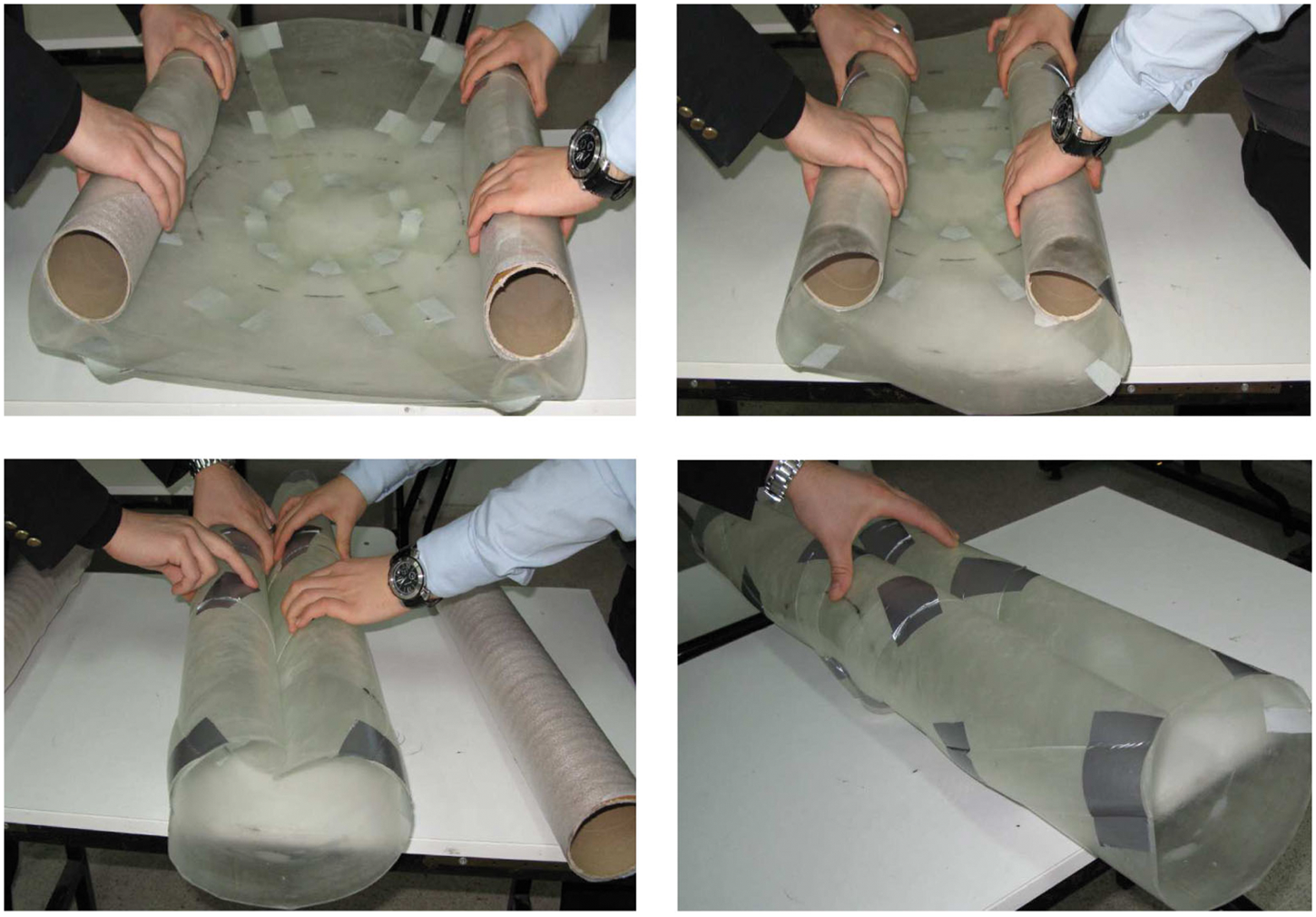
Conclusions
In this study, the bending behaviour of the curved elastic tape springs to be used as a support structure in deployable space reflectors is analysed by FEM and an analytical approach. 2-D and 3-D bending analyses are conducted for the curved tape springs made of triaxial weave carbon fibre/epoxy. The analyses are conducted for two different tape configurations A and B which initially have positive and negative Gaussian curvatures, respectively. The initial curvatures, subtended angle, projection length, and 3-D fold angle are considered as the design variables. In the 2-D folding analyses of the tape springs, the peak bending moments significantly reduce due to initial longitudinal curvature. Both the peak and steady moments increase with the increased subtended angle. The simple analytical approach is in agreement with the precise FE results, although there are up to 10% difference of the steady moments and the fold radius in most of the cases.
In the 3-D folding analyses of the tape springs, the peak moments about the fold line further reduce due to the presence of the 3-D fold angle. Significant moments about the perpendicular axes to the fold line occur during folding. These moments are relatively lower for the tape spring A for lower 3-D fold angles. The tape spring A has also lower strains in folded configuration compared to B.
The study of both the tape spring configurations as a rib of the thin shell reflector shows that both options met the stiffness and mass requirements of the reflector. The natural frequency of the reflector supported by the tape spring A is twice higher compared with the reflector supported by B.
The breadboard model shows the feasibility of the usage of tape springs as a support element of reflective surface. It has the ability of folding and self-deploying. The ribs are connected to the surface using duct tapes which allow the ribs for folding. However, the ribs of the tape spring A are connected to the reflective surface of the full-size reflector along their edges which could not fully comply with the folding of the reflective surface. Connection of the ribs to the reflective surface should be further studied in future design and analyses.
Footnotes
Funding
This study was funded by the Scientific and Technological Research Council of Turkey (grant no. 109M421) and Scientific Research Fund of Pamukkale University (grant no. 2009FBE007). Financial supports are gratefully acknowledged.