
Abstract
The fracture experiments of the monofilament composite material system is applied to evaluate the interface shear strength of the composite materials for a long time. This paper is based on the polarizing microscope, establishing the online observation fracture experimental platform and analyzing the formation process of the fracture according to fracture injury patterns of the carbon monofiber resin matrix composite system in the fracture experiment. Secondly, this paper also describes the forming process of the fracture injury patterns, diamond damage fracture, V damage fracture and double V damage fracture. The experiment shows under the tensile load. Matrix of different mechanical properties is the main factor to affect the carbon fiber fracture morphology and the stress distribution representation. Finally, by employing the finite element software ABAQUS as computing platform, and with the help of the user-defined subroutine, the numerical analysis method of the fracture process in the monofilament composite system is put forward. From The Micro Perspective, this new method explains the internal damage mechanism of composite material, which is the result of different fiber directional properties of interface between fiber and matrix due to the different chemical reaction extent of the interface phase.
Introduction
The carbon fiber reinforced composite materials become the new favorite of the materials application and research field due to its superior performance, manufacturing process and designability. With the further understanding, the monofiber model and the multi-fiber model are widely applied in the microscopic mechanical properties study of composite materials. In numerous experiments, the evaluation of interface shear strength 1 is the most important purpose and there are a lot of works concentrating on the reason of the different interface shear strength given by the fracture experiments, droplets debonding experiment, pull out experiment and ejector experiment. From the contrast of the four experimental methods, the fracture experiments can quantitatively evaluate the interface shear strength in the fracture experiments. Besides, it is found that the damage of the fiber in resin also approximates to the internal microscopic damage model of the composite laminates. Therefore, the fracture experiment is the most easy microscopic experimental method to observe the damage of the fiber and the stress field distribution.
The X-ray diffraction stripes analysis technique,2,3 acoustic emission technique, 4 – 12 Raman spectra measurement technology, 13 – 21 polarized light microscopy observation system 22 – 24 are employed in the test of interface mechanics performance, a new experimental system with the traditional method and new measurement is established. This system is used to detect the interface shear strength, the failure process of the plastic substrate and the influence and the stress concentration factor of the fiber spacing. This paper first introduces the observation platform of the fracture experiments briefly, and then evaluates the interface shear strength of two material systems. The mechanical properties of the two resin systems are measured, and the damage patterns are observed to estimate performance parameters of the material which influences the stress distribution on the fracture. This paper also provides the experimental platform to foresee and analyze the mechanical properties of laminates and the stress distribution of the damage. From the view of mechanics, properties of the fiber reinforced materials are decided by three main aspects, including fiber reinforcement, resin matrix and interface. According to different damage patterns of monofiber system, finite element analysis of the interface debonding and matrix crack with the employment of contact element, element birth and death and cohesive model in the universal finite element software is realized. Simulation analysis results have a good agreement with the experiment which reflects the basic failure mode.
Experimental
Design and construction of the fracture experimental platform
The whole set of fracture tests device is built, including the optical microscope lens, 3CCD and computer screen, and the displacement loading devices formed by the fixture and loading shaft. To realize online monitoring samples failure process, the microscope is located in the middle of the loading devices and the loading devices are set respectively on the both sides of the transmission light, to make the polarized light project on the samples. In order to search for the monofiber in the samples, micro-mobile platform is fixed on the bottom of the microscope to control the displacement of it so as to make the sample image lie below the objective. The experimental device is shown in Figure 1.
Design module of experimental device and the actual measurement system.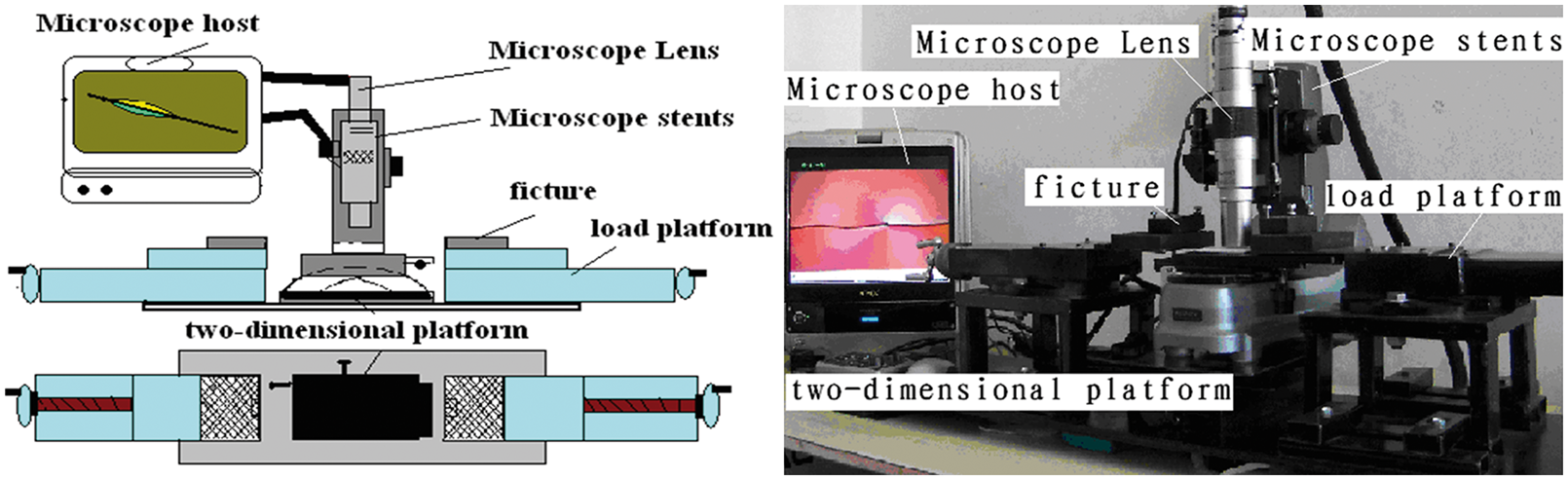
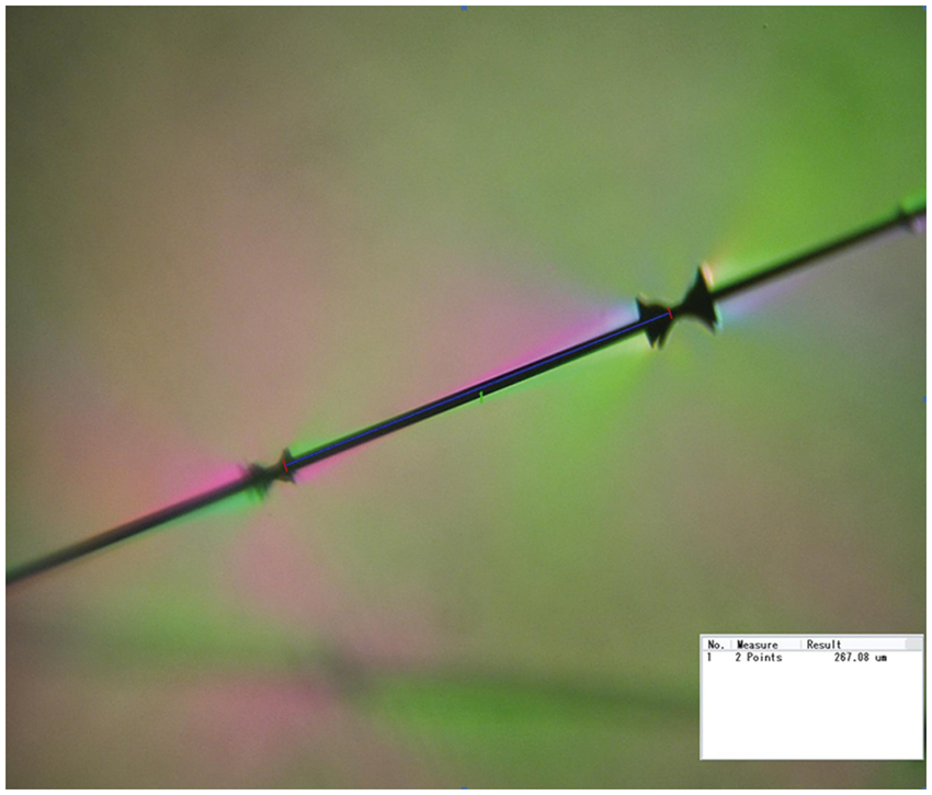
This experiment measures the saturated length of the monofilament fracture in the single carbon fiber T300/epoxy composite system and records the whole process of the fracture.
Mould design and sample production
The molding mould was used to solidify the sample. The mould has two parts: stainless steel slab stuck with stripping cloth and a metal frame. The size of the hollow mould and the experimental method is carried out by the ASTM D638-2003.
During the sample manufacture process, the carbon monofiber is fixed on the center line at first. The sample chose here is carbon fiber T300, the resin system 1 is synthetic of the epoxy resin128, the curing agent 593 and the toughening agents with mass ratio 100:30:10, and the mass ratio of system 2 is 100:30:5. During the curing process, the sample is heated up to 50°C first, then the temperature is maintained for an hour and at the same time the sample is vacuumed, after that, the temperature is heated to 80°C under the rate 2°C/min, and then the temperature is maintained for another 7 h, at last the sample is naturally cooled.
Figure 2 is the carbon fiber fracture saturated length of the monofilament composite material system 1 and 2 measured in the experiment.
Interface shear strength in the epoxy resin fracture experiment.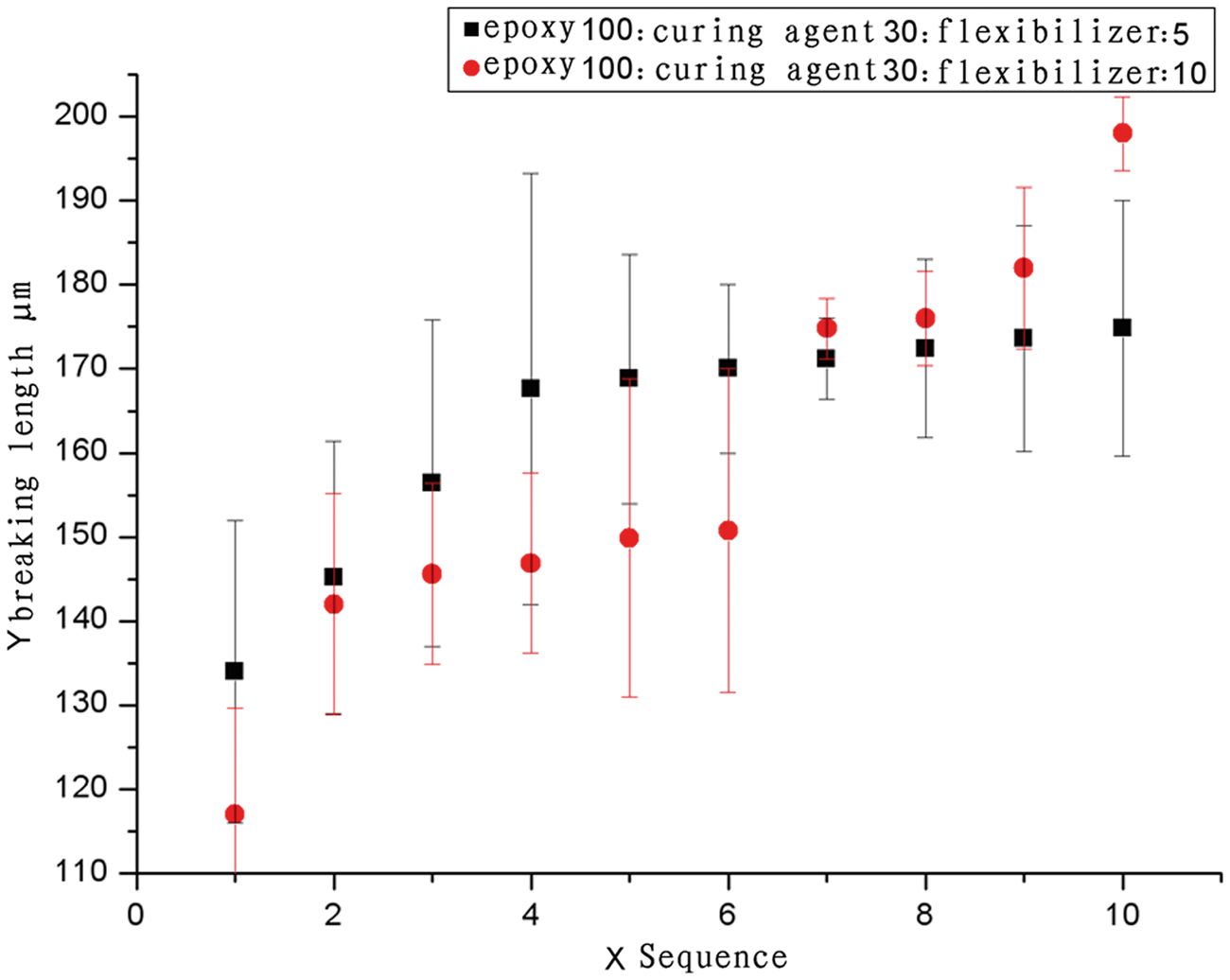
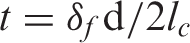
The calculation formula of the interface shear strength with shear lag theory is as follows:
The fracture damage pattern analysis
The transmitted light source of the polarizing microscope VHE900 is used to illuminate in experiment. The horizontal load is applied on the sample by the fixture. The sample is clamped in the centre of the 2 d adjustment test platform so as to observe the experiment process. Light-emitting component is put into the light source under the soleplate and the Polaroid is put in front of light source to polarize the incident light. Then the height of the camera is adjusted, and the loading device with the sample is put above the microscope platform to make the light source face to the gage length of the sample. The height of the camera is adjusted a second time until the brightness of the light source has an appropriate index for the search of the single fiber. After that, the Polaroid is inserted into the camera to analyze for the second time. Then the controlled load is applied on the sample. The change of the fiber, the change of matrix and its response to the polarized light are observed and recorded. It is observed that there are colorful stress field near the fracture and bright slit of light at the edge of the fiber.
The result of the experiment shows that there are obvious differences between the stress fields of different fiber fractures. The mechanical properties of material are analyzed to further recognize this phenomenon.
The mechanical properties tests of system 1 use ASTM D638 as the standard. The results are as follows: (Table 1; Figures 3 and 4).
Displacement vs. load curve of system 1. Stress field morphology of system 1. Sample size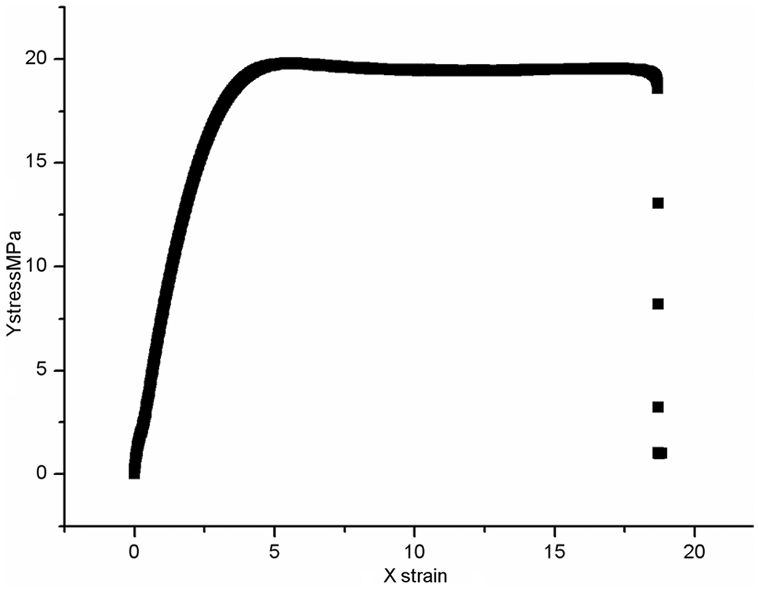

From the curve of load vs. displacement, the material system is bi-linear flexible resin. The regions of the stress mainly concentrate near the fracture of fiber and have no great range influence on the matrix. System 2 also uses the same standard as system 1 (Table 2; Figures 5 and 6).
Displacement load curve of system 2. Stress field morphology of system 2. Sample size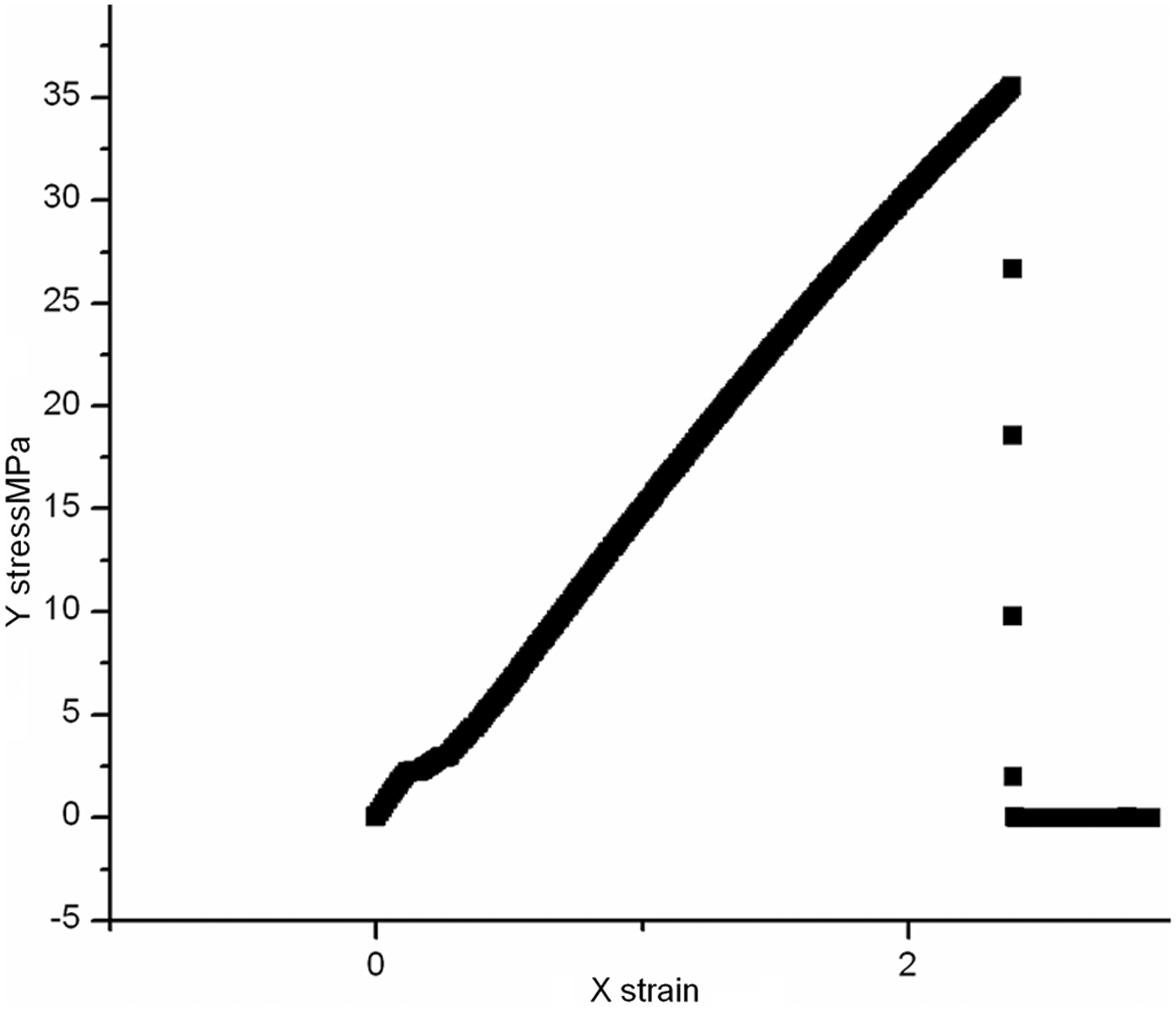
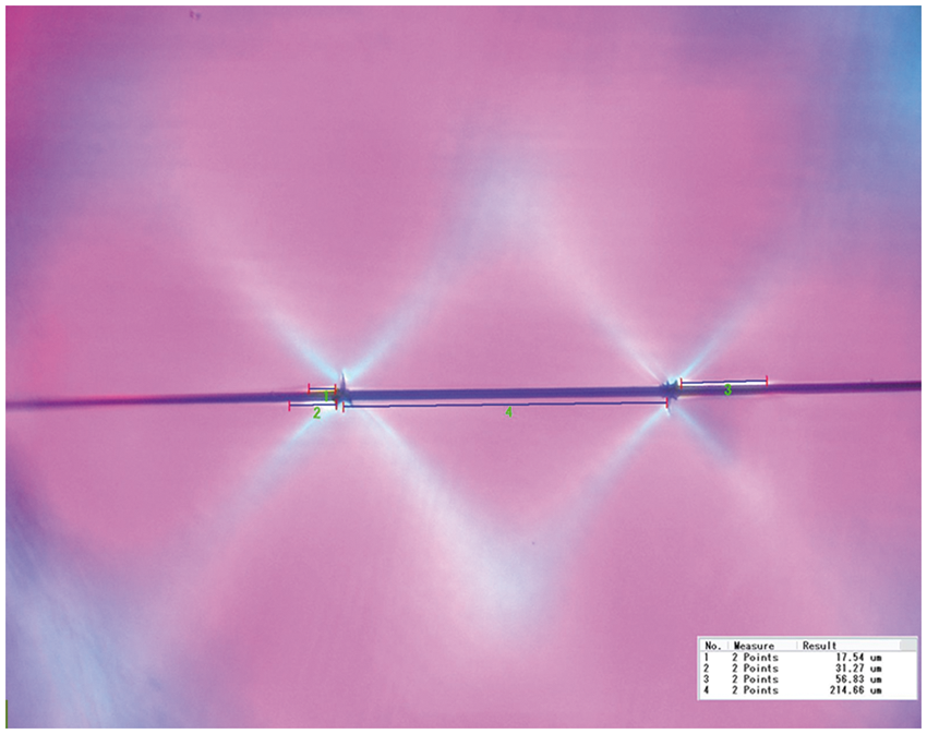

From the curve of the load vs. displacement, it can be observed that the modulus of this system is larger and the system is elastic. The stress-affected region near the fiber fracture presents a 45° shear zone and forms a cross-matrix stress distribution. The fracture of single fiber affects the matrix in greater range. From the analysis of these two systems, we can know the class of resin system has a great effect on the stress field distribution near the fracture, the higher the modulus, the greater the range of cross-distributed stress.
In the fracture experiments of the two samples with different mechanical properties, three fracture modes of monofilament are observed. The formation procedure of different fracture modes are as follows (Figure 7, Figure 8 and Figure 9).
Small diamond split forming process.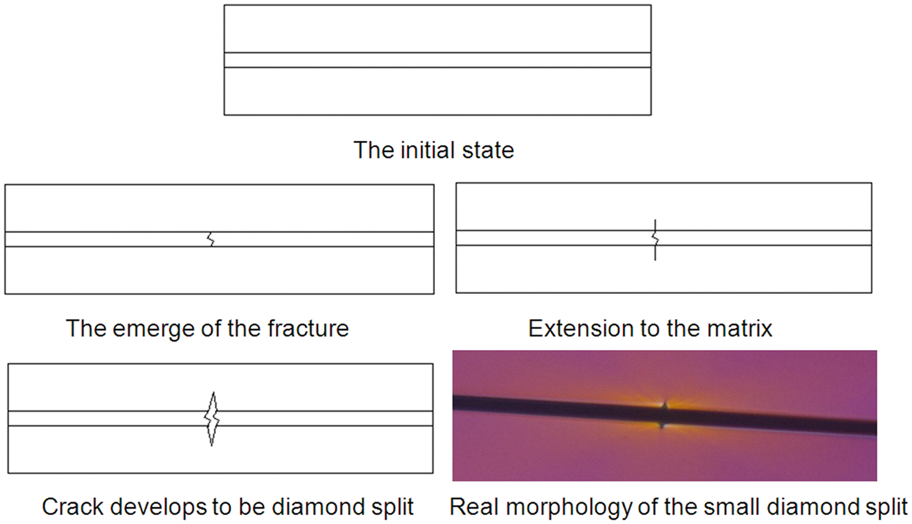
Small diamond split forming process is as follows: At the beginning of the fracture experiment, the fiber, interface and matrix are in perfect condition. As the breaking elongation of the fiber is smaller than that of the resin under load, the fracture emerges first on the fiber. If the interface bonding strength near the fracture is big, the crack of the fiber extends directly to the resin. If the load continues, the crack will extend to a diamond split (Figure 9).
Double V split forming process.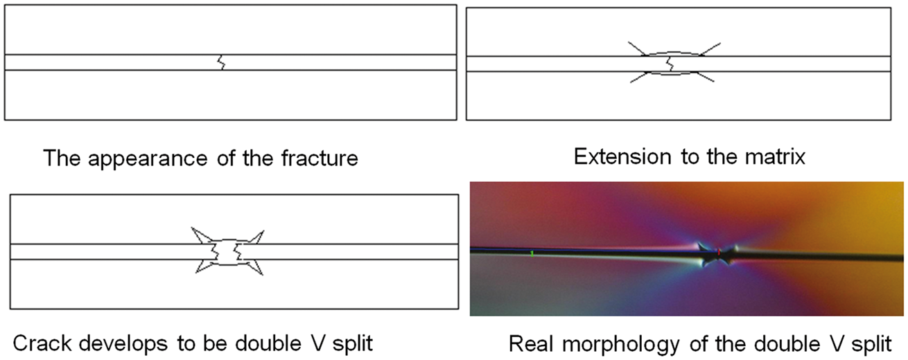
Double V split forming process is as follows: At the beginning of the fracture experiment, the fiber, interface and matrix are in perfect condition. As the breaking elongation of the fiber is smaller than that of the resin under the load, the fracture emerges first on the fiber. If the interface bonding strength near the fracture is small, the crack of the fiber will extend along the interface. When the crack extends to a stronger interface, it will turn its direction and extend into the matrix. If the load continues, the crack will extend to a double V split (Figure 8).
V split forming process.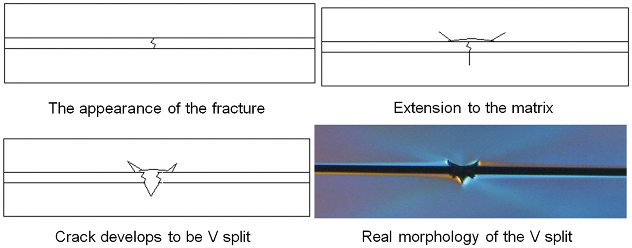
V split forming process is as follows: The V split is the mixture of the two fracture models above. The main reason is the different interface shear strength of two sides of the fiber. In the fracture experiment, the fracture also emerges first on the fiber. As shown in the plane observation figure, the interface bonding strength on the upside of the fiber near the fracture is smaller, the crack extends along the interface and then turns into the matrix. As the interface bonding strength on the downside of the fiber near the fracture is stronger, the crack extends directly to the fiber. If the load continues, the crack will extend to a V split (Figure 9).
Results and discussion
The result above shows the various damage modes in the monofiber composite system, including the fiber crack, the damage of the matrix around the fracture and the debonding of interface. The main reason of damages is the failure of material. To explain the damage of monofiber composite system in material level, general finite element software ABAQUS and the subroutine USDFLD are employed to simulate the damage modes of monofiber composite system and analyze the mechanical behavior of the matrix around the fracture.
The finite element model is established and along with the constitutive model of fiber and matrix, this finite element model describes the failure behavior of fiber and matrix damage in the fracture and damage process of the monofilament composite system.
The fracture process of the monofilament composite system includes two stages: elastic load transfer stage and damage developing stage. In the elastic load transfer stage, part of the external load of matrix is transferred to enhance fiber through the interface, the stress of fiber increases gradually. Under the external load, the vertical stress contours map of the system is presented in Figure 10. From the figure, it is clear that vertical stress of the fiber is larger than that of the matrix. This indicates that the fiber is the main load-carrying parts of the monofilament composite system. Figure 10(b) shows the axial stress distribution of the fiber under different values of loads.
Numerical results of elastic load transferring stage: (a) Contours of stress distribution and (b) fiber axial stress changes with the load.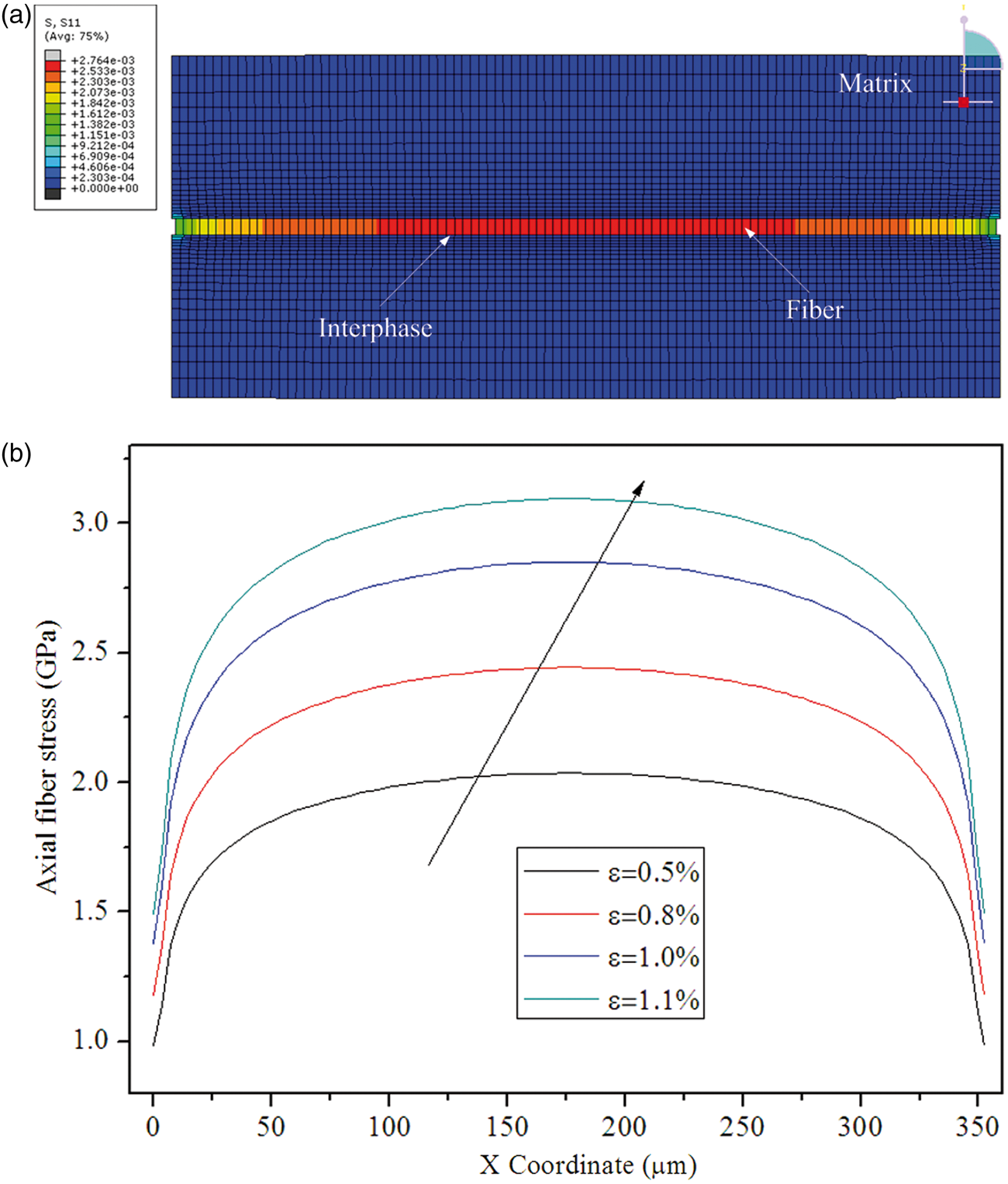
In the damage stage, in order to make the fiber fracture many times, the geometry size of the existing model needs to be modified. From the analysis, only when the length of the fiber in the system is longer than the invalid stress transfer length can the fiber fracture happen. So here the axial length of existing model is enlarged to make sure that fiber fractures many times under the external load. In addition, in order to simulate the stress redistribution of the matrix around the fiber fracture, radial radius of the model needs to be enlarged, and the change of the radial radius has little effect on the axial stress of the fiber, so that the analysis about the stress redistribution area in the matrix around the fracture can be better made.
The damage stage of the monofilament composite system is simulated and analyzed. When the stress in the fiber is greater than its strength, the fiber will crack for the first time. After the crack, the axial stress distribution of the fiber is shown in Figure 11.
Contours of axial fiber stress after fiber fragment.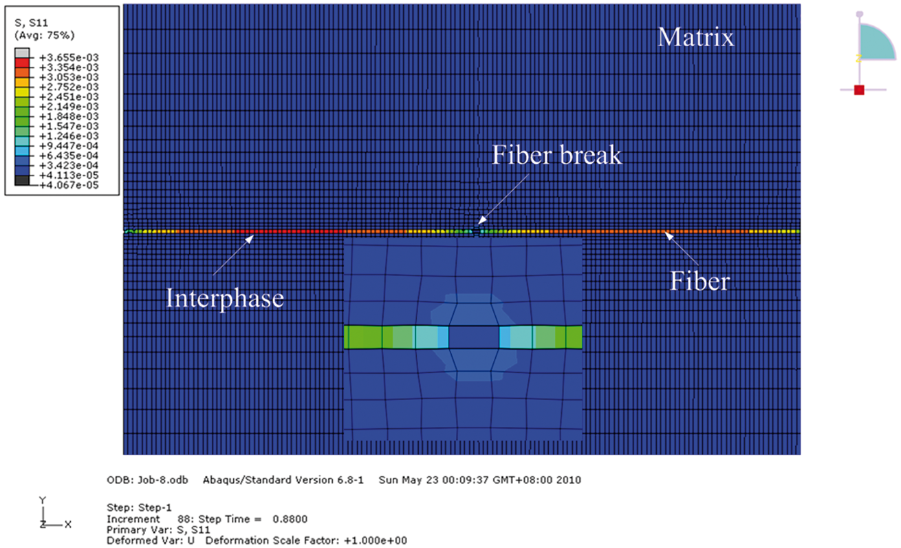
Figure 11 indicates that the axial stress of the failure fiber element is almost zero when the fiber fractures. Figure 12 presents the relationship between the stress of the failure fiber element and the applied strain load (The load is normalized.).
The axial stress curve of failure fiber element.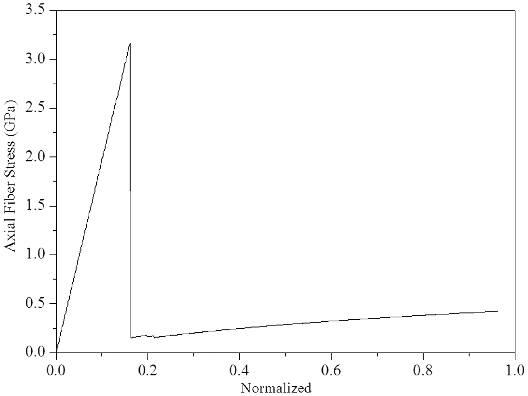
In Figure 12, in the elastic load transfer stage the stress of the fiber element increases with the external load. When the stress is more than its strength, the stress in the element decreases suddenly, and that means the element failure. After the failure, the stress raises slowly with the increase of the external load.
After the fracture of the fiber in the system, for the connecting function of the matrix, the fiber in the system still can carry load. So, as the external load increases, the stress in the fiber will recover gradually. After the first crack of the fiber, the axial stress distribution is shown in Figure 13.
Distribution of axial fiber stress after the first fiber fragment.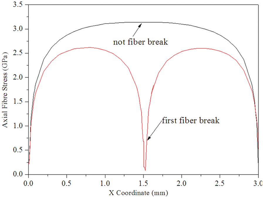
In Figure 13, after the fracture, the stress distributions in each segment of the fiber are the same. With the increase of the external load, the fiber in the system will crack for the second and third time. However, the carrying capacity of each segment decreases. The redistribution of the stress in the fiber is shown in Figure 14.
Redistribution of axial fiber stress after the third fiber fragment.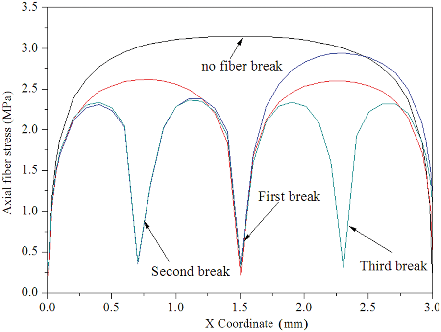
Figure 14 shows that after the first fragment of the fiber, with the increase of the external load, the second fracture emerges at the left fiber segment. The right segment then carries more external load at the same time, so the axial stress of this fiber increases (but still smaller than that before the fiber fractures). When the stress is greater than the strength of the fiber, the inner fiber cracks for the third time and the stress distribution of each fiber segment keeps the same.
The fiber fragment will cause the stress concentration near the fracture and make its redistribution. The redistribution form of the stress in the matrix near the fracture is shown in Figure 15.
Contours of von Mises stress in the matrix near fiber fragment.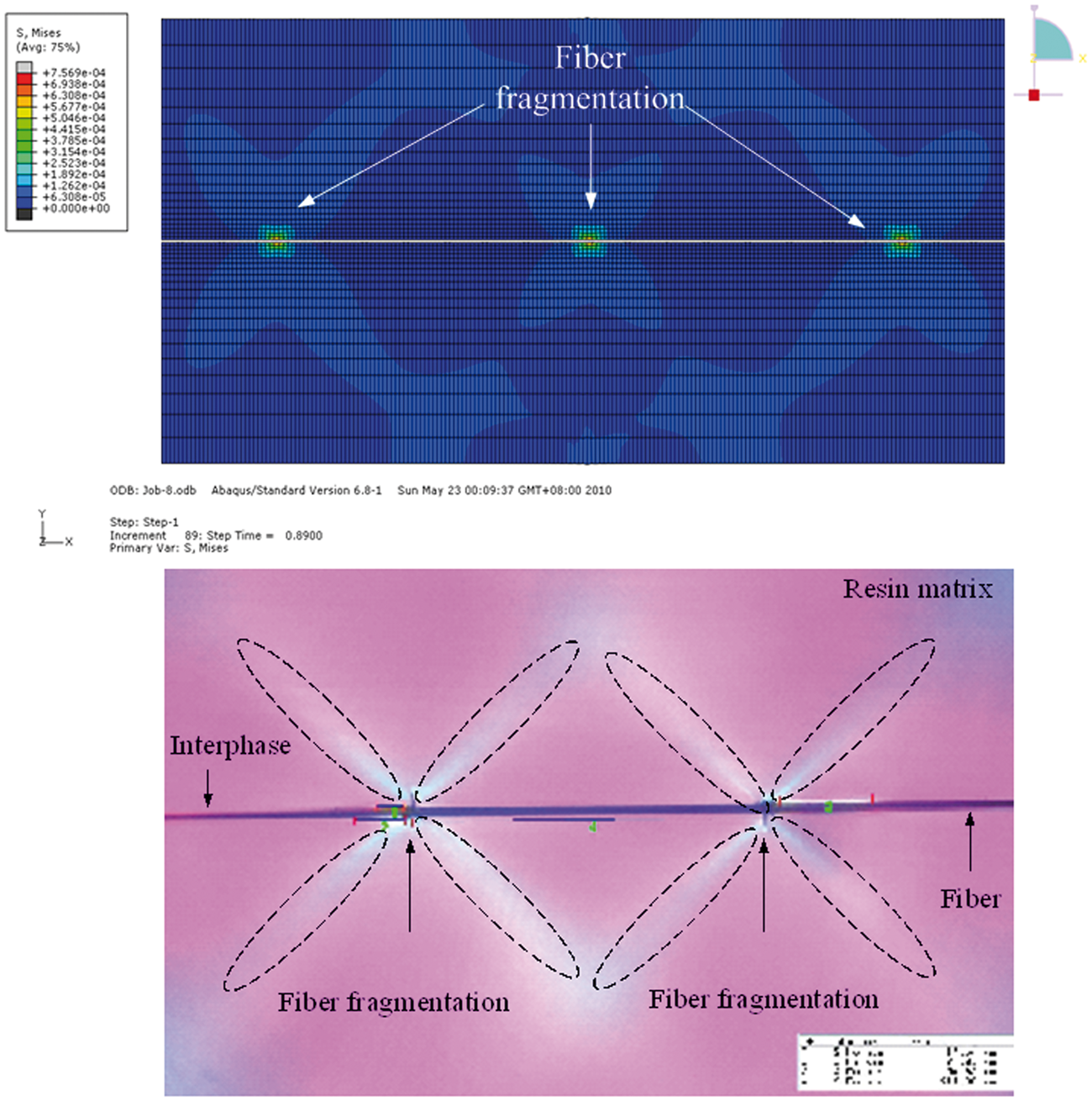
Figure 15 indicates that the matrix stress of the regions that are in 45° angle corresponding to the fiber is greater, which coincide well with the polarized light image of the experimental result. With the increase of the external load, the damage of the matrix will occur in this area definitely. Experimental result show that the damage emerges near the fiber fracture. In order to decrease the calculation costs, it is only needed to add a material constitutive model of the damage mechanical behavior to the matrix near the fiber in the simulation. The comparison of the simulation result and the experimental result of the matrix damage is shown in Figure 16, which indicates the correctness of the experimental analysis.
Damage model of matrix near fiber break.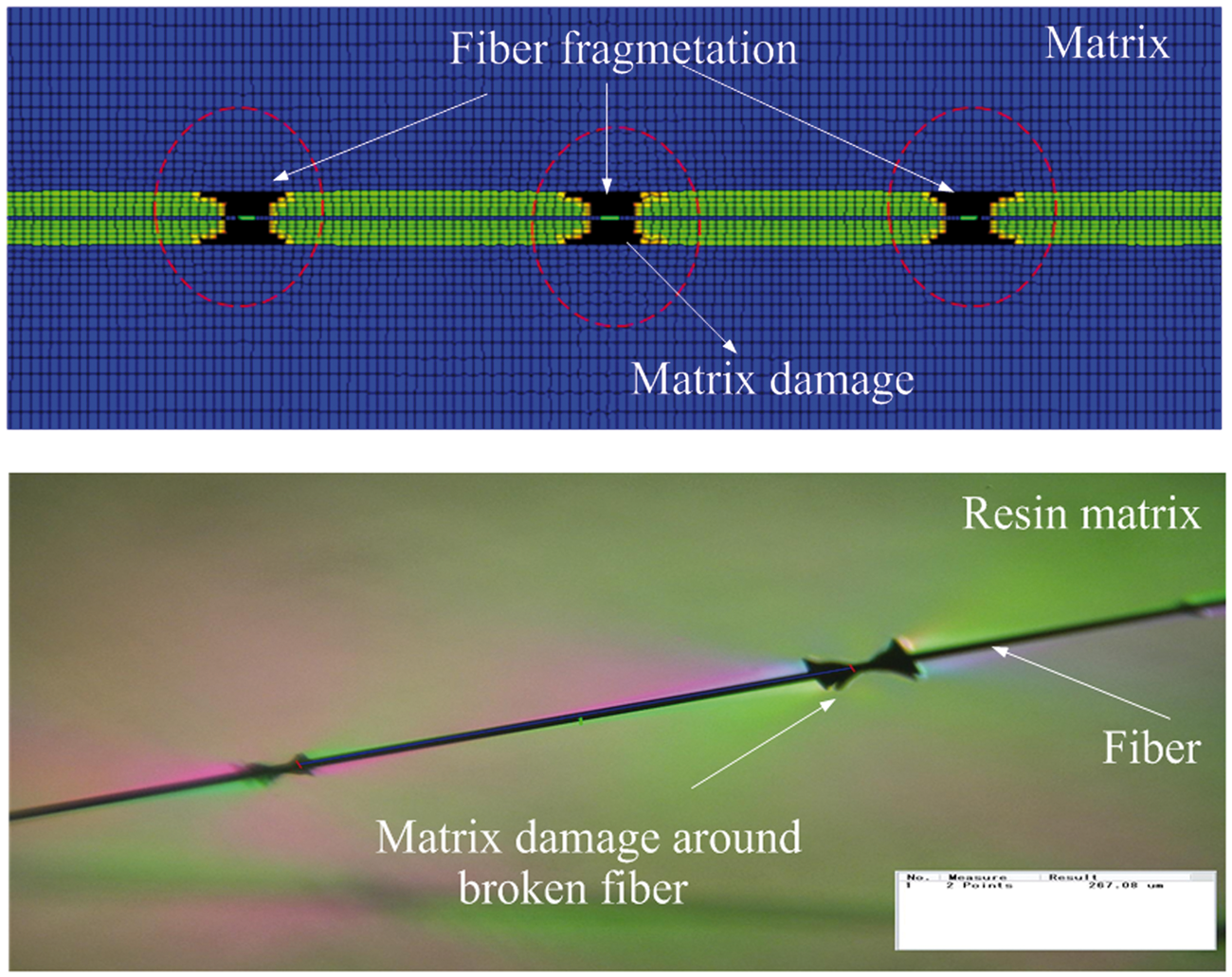
After the fiber fracture, shear stress will rise in the interface near the fracture. It indicates that the shear stress on the interface has the anti-symmetrical distribution, which is consistent with the experimental phenomena and further demonstrate the correctness of the numerical method. With the increase of the external load, the debonding of the interface occurs in this area.
Conclusion
This paper characterizes the damage mode near the fiber fracture of the single composite system damage in experiment, with the help of polarizing microscope. The result shows that when the fiber cracks, the polarizing image of matrix will present an obvious “cross” while an anti-symmetrical distribution will occur on the interface near the fracture. The damage mode of the matrix near the fracture is complicated and also presents “cross” shape.
Experimental results indicate that for different surface morphology of the fiber and different degree of chemical reaction, the adhesive strength of the axial interface are different and discrete. As a result, there are three different fracture forms in experiment, such as small diamond split, V split and double V split. The distribution of the stress field near the fracture mainly depends on the mechanical properties of the matrix. With the increase of the matrix modulus, the stress field enlarges gradually. The experimental result provides the powerful basis for the establishment of the analysis method of the damage process of monofiber composite system.
With the help of ABAQUS as the calculation platform, the numerical analysis method of the system damage process based on the user subroutine is established. Through the comparison with the experimental result, the correctness of this analysis method is proved, which provides the numerical results for the gradual damage analysis of monofiber composite system.
Footnotes
Funding
This work was supported by the National Natural Science Foundation of China (grant no. 11102054), the Key Project of Science and Technology of Heilongjiang (grant no. GZ09A207), Key Laboratory Opening Funding of Advanced Composites in Special Environment (grant no. HIT. KOLF. 2009030) and China Postdoctoral Science Foundation (grant no. 20100471081).