
Abstract
Repair of a cracked aircraft structure by an adhesively bonded composite patch has gained lot of importance in extending the fatigue life as well as improving the structural integrity of it. In the present work, an experimental study is carried out using digital image correlation (DIC) technique to analyze the behavior of single and double-sided adhesively bonded patch repair of an inclined center cracked aluminium panel subjected to uniaxial tensile loading. Further, the shear strain distribution in the adhesive layer is also estimated using the DIC technique. Shear strain concentration at the overlap edge in the adhesive layer is very high leading to patch debonding. Further, optimum patch dimension and patch thickness for the given cracked panel are arrived using a genetic algorithm-based optimization technique in conjunction with finite element analysis (FEA). With the optimum patch configuration, a 3-D FEA is further carried out and the obtained results are compared with the experimental prediction from DIC. The DIC prediction correlates with FEA contours on overall basis.
Keywords
Introduction
During the service life of an aircraft, it is subjected to severe structural and aerodynamic loads which results from repeated landings and take off, fatigue, ground handling, bird strikes, and environmental degradation such as stress corrosion. However, due to limited budgets and escalated procurement costs, aircraft service life needs to be extended beyond their design life. Hence, a reinforcement or repair of damaged aircraft structure is essential to improve its service life. These repairs can be generally classified as externally bonded patch repair1,2 or scarf repair3,4 depending on the structure to be repaired. Scarf repair is mostly preferred for primary load bearing structures, whereas externally bonded repair is preferred for secondary load bearing structures. The adhesively bonded patch repair reduces stresses in the cracked region by doing load transfer through patch into panel and thereby prevents the crack tip from opening and thereby from growing. The repair on these load-carrying structures must restore both strength and stiffness. Repair of aircraft structures made of aluminium using composite patch has been initiated by Baker et al. 1 in the early 1970s mainly to enhance the fatigue life of cracked aircraft structures. From geometrical consideration, bonded patch repair broadly falls into two categories: double sided (symmetric) and single sided (asymmetric). Based on the practical applications and space availability, symmetrical or asymmetric repair is considered. 2
Over last two decades, great advancement has happened in the area of finite element analysis (FEA), especially in case of composite repair applications.5–15 Chukwujekwu Okafor et al. 5 conducted both experimental and FEA for analyzing the stress distribution of cracked plates repaired with single-sided octagonal patch. They found that the zone of maximum stress shifted from the crack front in the case of cracked specimen to the patch edge in repaired specimen due to high peel stress development at the patch overlap edge. The peel stresses in bonded joints normally peaks at the overlap edge, which in turn can cause failure of the adhesive layer thereby reducing the performance of the repair. To reduce the severity of this peel stresses occurring at the overlapped ends, Duong 6 suggested usage of tapered patch and in the present work tapered patch is considered. There are only few works available on repair of panels with mixed-mode crack orientation.7–12 Hosseini-Toudeshky et al.7,8 have carried out fatigue crack growth tests for single-sided repair applied to thick and thin panels containing an inclined center cracks with patch of different lay-ups and thickness. Ayatollahi and Hashemi9,10 have done FEA based investigation to study the effect of composite patching on the stress intensity factor (SIF) reduction for an inclined center-cracked panel under different mode mixity.
Recently, Ramji and Srilakshmi 11 have studied mechanics of both single- and double-sided repair of an inclined center cracked panel using FEA. Ramji et al. 12 have also investigated the influence of different patch shapes on the repair performance in case of double-sided repair panel. They have found that extended octagonal patch shape has performed better in SIF reduction. It should be pointed out that a badly repaired structure can be more dangerous than the unrepaired one. For such a reason, the design of efficient patch can be done by estimating the optimal patch dimensions with respect to SIF reduction near the crack tip. Mathias et al. 13 have conducted genetic algorithm (GA)-based optimization analysis for getting optimum ply orientations and patch shape in the case of repair of aluminium panel with a center hole. They have used carbon fiber-reinforced polymer (CFRP) as the patch material. Brighenti et al. 14 have employed GA-based optimal search for finding the optimum patch shape applied to a straight center cracked panel. They have found that skewed patch performs best for such panel. A very limited study exists on the estimation of optimum patch dimensions applied to an inclined cracked panel involving any optimization technique.
Most of the work existing in the area of composite repair involves FEA-based study and a limited study exists on whole field experimental analysis applied to understand the stress/strain distribution at patch overlap edge as well as to measure the strain in the adhesive layer by assessing the development of peel stress or shear stress at overlap edge with increasing load value. Traditionally, researchers have used reflection polariscope 16 and strain gauges 2 for strain measurements in repair study. Off late, digital image correlation (DIC) is used in the field of experimental mechanics for its accuracy and relatively simple optics capable of whole field estimation of surface displacement and strain.17–25 DIC is easy to use since it involves simpler surface preparation on specimens. All the aforementioned studies related to adhesive strain measurement could be easily carried out using the DIC technique.
In the present work, initially, FEA in conjunction with GA-based approach is used to arrive at the optimum patch geometry pertaining to a global minimum SIF at crack tip. Later on, an elaborate experimental study involving DIC is carried out to investigate the whole field surface strain distribution on the repaired panel involving optimal patch geometry. The CFRP patch geometry chosen is of extended octagonal shape with tapered edges. But in the repaired panel, adhesive layer is the weakest link which would fail first under continuous loading. So, surface peel and shear strain over the adhesive layer especially at overlap edge is estimated using DIC technique. Also, the strain data obtained from DIC will be useful for getting stress vs strain behavior of the panel and also useful for predicting the ultimate strength of the repaired system. Finally, a three dimensional FEA study is carried out to estimate the strain field and SIFs for the repaired panel having the optimum patch configuration. The obtained strain fields from FEA are compared with the DIC prediction.
Digital image correlation
DIC refers to the class of non-contact optical methods that acquire images of an object, store these images in digital form, and perform image analysis to extract whole field surface displacement and deformation measurement.18–22 It provides information about the displacements and strains by comparing the digital images of the specimen surface in undeformed and deformed states, respectively. In principle, DIC is based on pattern matching technique and numerical computing.
19
In DIC, one of the most commonly used approaches employ artificial speckle patterns on the surface of specimen and compares sub-regions (subsets) from “deformed” and “undeformed” images to obtain a full-field displacement measurements as shown in Figure 1. The simplest subset matching algorithm is the cross-correlation, which provides the in-plane displacement fields u(x,y) and v(x,y).18–22 For the cross correlation process, many subregions in the image are compared.
Schematic of subset matching DIC: (a) undeformed and (b) deformed.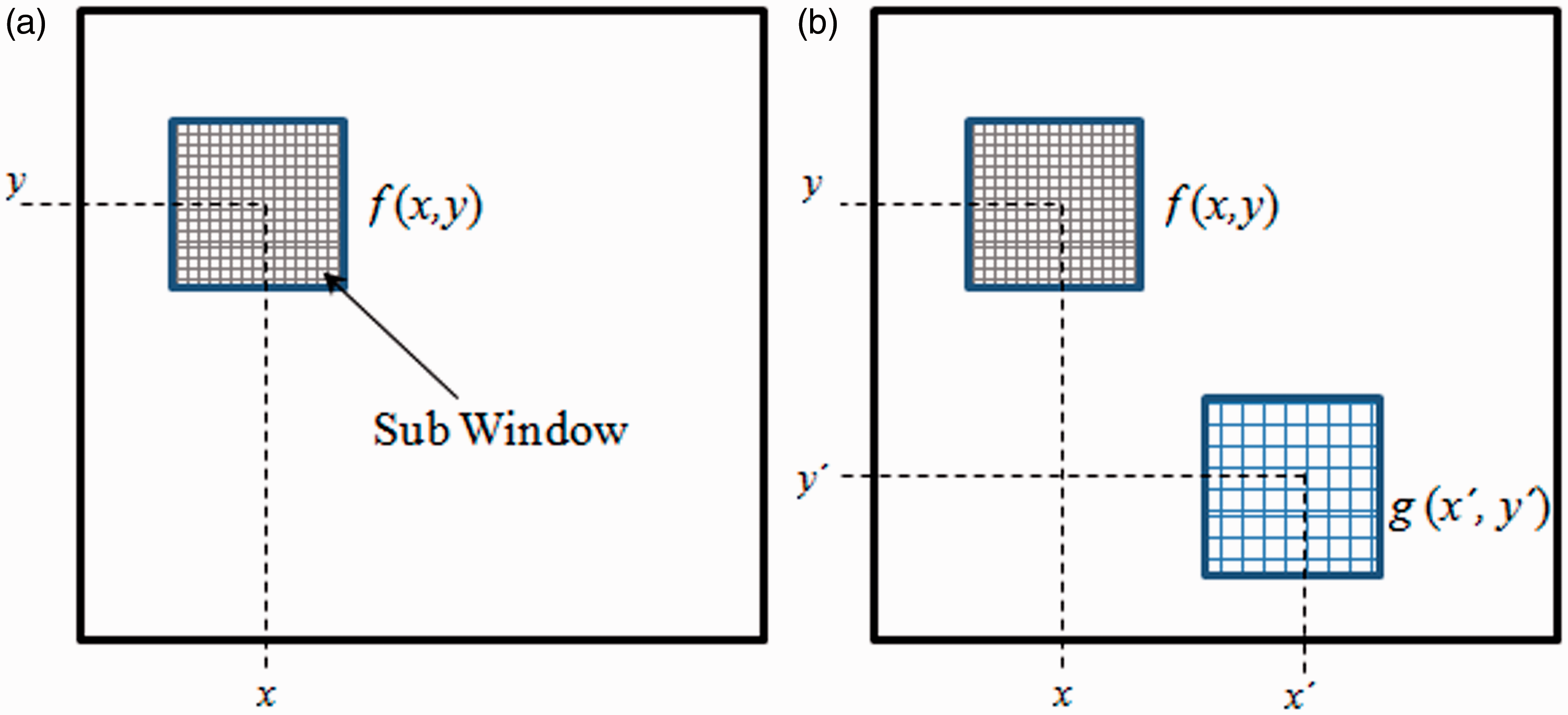
Moving least-squares (MLS) method is used to smooth the displacement field followed by a numerical differentiation of the displacement field to get the in-plane strain components. 22 In case of 2D DIC setup, only one camera is used for the measurement of in-plane surface displacements and strains, whereas 3D DIC setup has got two cameras for the measurement purpose. The 3D DIC setup utilizes a detailed calibration procedure to synchronize the camera co-ordinates and parameters. Once the cameras are calibrated, the sensor plane locations in the two views for the same object point can be used to determine an accurate estimate of the three-dimensional position of the common object location.18–22 After the calibration, the image acquisition process is synchronized so that both the camera acquire images simultaneously after triggering. In case of 3D DIC, one can get out of plane displacement in addition to in-plane displacement and strain.
Geometry and model configuration
The panel is made of aluminium alloy 2014-T6 plate having a dimension of 40 × 160 × 3 mm3, containing an inclined center crack ‘2a’ of length 10 mm. The crack is inclined at an angle of β = 45° with the horizontal. The specimen geometry considered in this work is shown in Figure 2. From an earlier study
11
it is observed that the unidirectional laminate with 0° lay-up gives highest reduction of SIF at the crack tip as compared to the other lay-up angle for a double-sided repair of inclined center-cracked panel. Because as the repair panel is subjected to in-plane tensile load, the maximum principal stresses field is along the loading direction and therefore the fibres lay-up in CFRP patch is kept along the maximum principal stress field, i.e. along the loading direction as it provides more stiffness. Hence, the patch is made of unidirectional (UD) CFRP laminate having a lay-up of 0° (i.e. fibers are aligned parallel to loading direction)
7
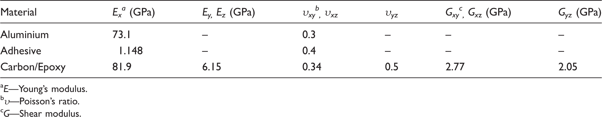
and is considered for both single and double sided repair. Araldite-2011 adhesive is used for bonding the patch over the cracked panel. The patch is bonded to the panel on one side in the case of single-sided repair and on both sides in the case of double-sided repair. The patch shape is of extended octagonal shape with tapered edges and its dimensions are arrived from finite element-based optimization technique and it is explained in the next section. The general material properties of aluminium panel, composite patch and adhesive are given in Table 1. The material properties of CFRP laminate are taken from Ref.25.
Geometry of the repair model with extended octagonal patch: (a) front view, (b) side view of symmetrical patch, and (c) side view of asymmetrical patch (all dimensions are in mm). Material properties. E—Young’s modulus. υ—Poisson’s ratio. G—Shear modulus.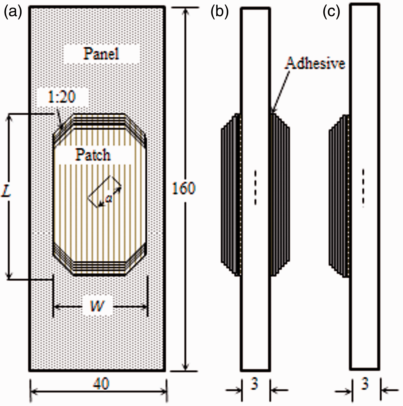
Finite element modeling and optimisation
Modeling of the cracked and repaired panel
FEA is the most effective tool for computing SIF in 3D fracture models. Modeling and analysis are done using ANSYS 13 which is a commercially available FEA package. For capturing very high stress gradient near the crack tip, a very fine meshing has been done around it as mentioned in Refs. 11,12 and shown in Figure 3. Initially, individual areas are created around the crack tip and meshed with plane element (mesh 200) having eight nodes. Later, all the areas are extruded in thickness direction to generate volume. Finally, all the generated volumes are meshed with 20 noded solid 186 element through sweep mode as shown in Figure 3(a). The panel, patch, and adhesive are modeled individually with the same 20 noded solid 186 element as per the dimensions. Convergence study for arriving at this particular mesh has already been carried out in an earlier study by Ramji and Srilakshmi
11
and the authors have adopted the same mesh here. In the thickness direction, the panel is meshed with six elements, adhesive with one element and patch with six elements as the number of layers are six. In this work, an extended octagonal patch shape is chosen as it gives lower KI and KII compared to other patch shapes as given in Ref. 12.
Finite element model: (a) cracked panel, (b) zoomed portion of crack tip, (c) zoomed portion of repaired panel with tapered patch, and (d) line diagram showing applied boundary conditions.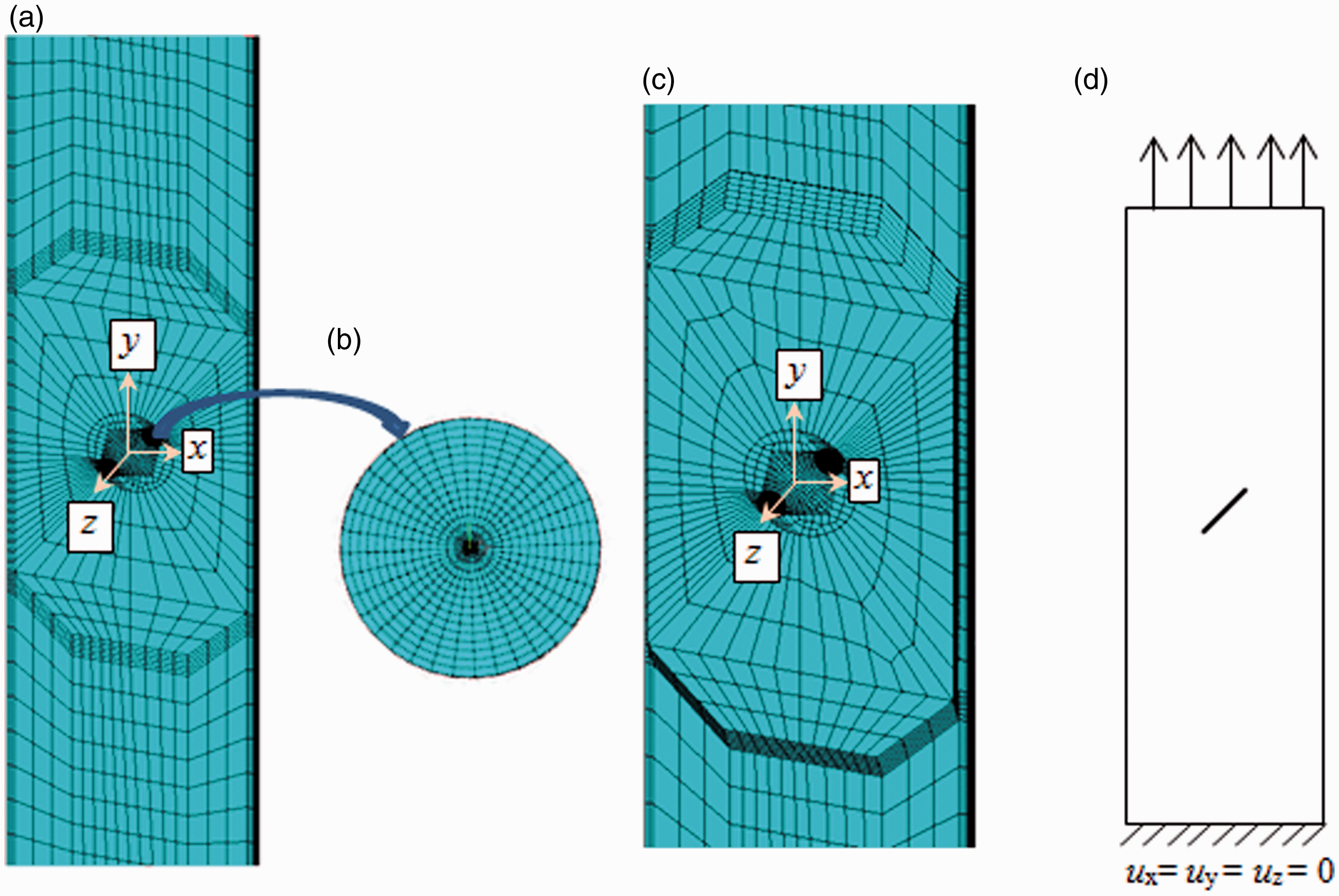
As the patch is made of a composite laminate having 0° lay-up, the layer angles are defined by assigning appropriate element coordinate system to the patch elements.12,26 Each layer is assigned one element in the thickness direction. It is assumed that patch is perfectly bonded on to the panel by the adhesive layer and it is simulated using multipoint constraint (MPC) algorithm. In MPC algorithm, all the three degrees of freedom are constrained. The MPC algorithm involves contact and target surfaces which come into contact with one another. MPC internally adds constraint equations to tie the dof's of the corresponding nodes between contacting surfaces such that no relative displacement exists between nodes and surfaces. It is a direct, efficient way of bonding surfaces at interfaces. 27 Figure 3(a) shows the finite element model of the inclined center-cracked panel. The zoomed portion of mesh surrounding the crack tip is shown in Figure 3(b). Figure 3(c) shows the single-sided patch repaired model, and the double sided patch repaired model is similar to it but contains patches on both sides. Regarding boundary condition, all dofs of nodes along the bottom surface (y = −L/2) are arrested (see Figure 3d). A tensile load of 15 kN is being applied as a pressure load on the top surface of the panel. The crack front is assumed to be normal to the panel surface, 12 but in real situation as the crack front grows it need not be perpendicular to the panel’s surface resulting in mode III SIF. Hence, in this study all the three modes are considered and respective SIF’s are estimated from energy release rate (G) using virtual crack closure technique (VCCT) for the given initial crack length as described in the next section.
Optimization using GA-based approach
GA is an efficient global search optimization method which operates on a population of potential solutions rather than from one single solution. It works on the principles of natural selection and genetics. In recent years, an increasing number of GA’s applicability in single-objective optimization is seen in the field of reliability and maintainability analysis. In single objective optimization, the solution is only a single point but in the multi-objective optimization solution is family of points known as Pareto-optimal set. In case of a single objective optimization, the comparison is trivial since a vector solution X is better than Y if the corresponding objective function (fitness) value f(X) is greater than f(Y). If there are N objective functions, two solutions X and Y must be related in terms of dominance of one solution over the other with respect to all N objectives. As a result of the multi-objective search process, convergence is achieved on a Pareto-optimal region of non-dominated solutions which can be subjectively managed by the decider to identify the preferred solution.
28
The application of GA and other rank-based algorithms to multi-objective optimization is of great attention in mechanics area. Mostly numerical technique such as FEA is preferred for generating the initial population for GA-based optimization study.
29
The optimization problem can be stated as
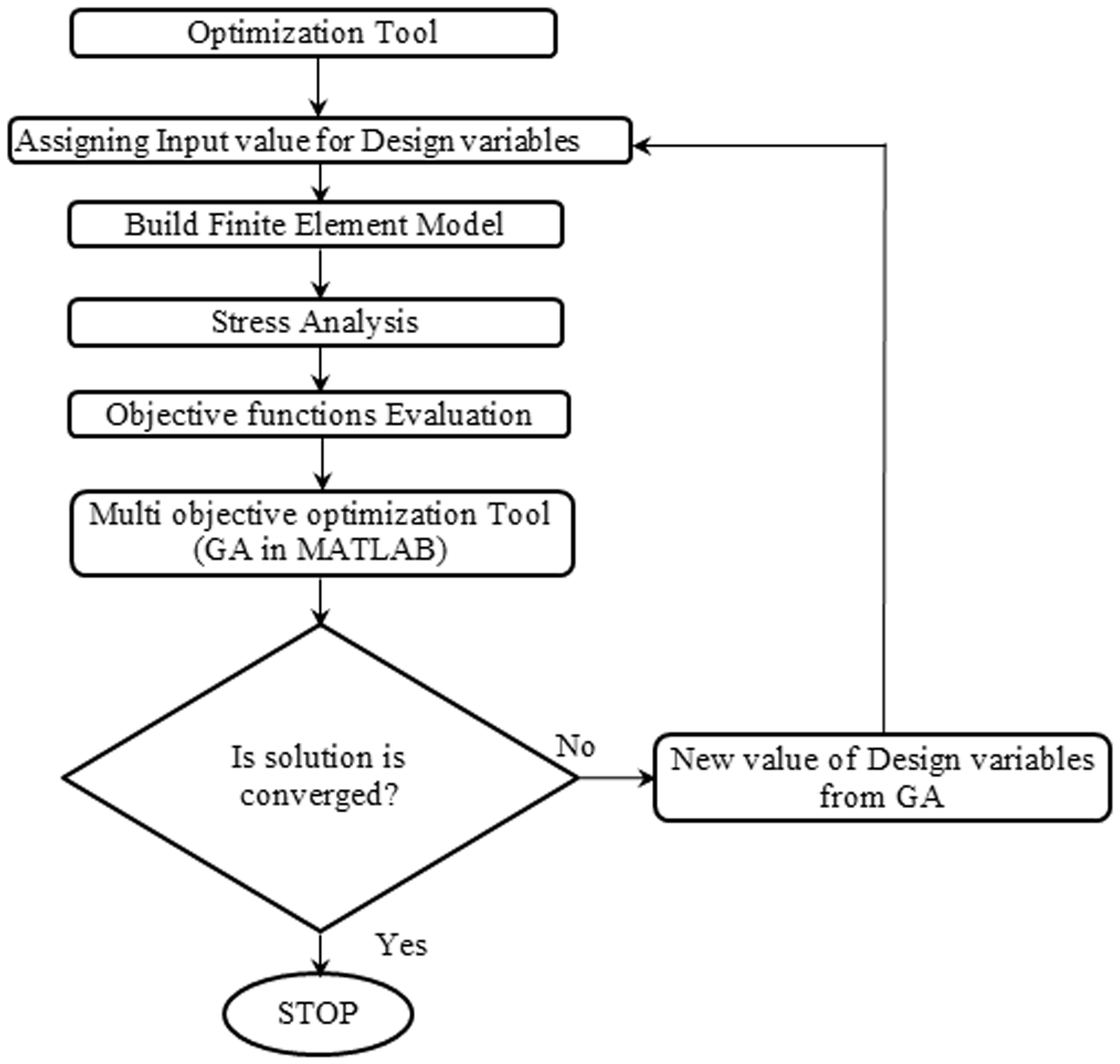
Flow chart describing the optimization procedure using genetic algorithm in conjunction with finite element analysis.
SIF evaluation
The analysis is carried out in the linear elastic fracture mechanics (LEFM) frame work. SIF is estimated from energy release rate using (VCCT)30 approach and VCCT can be only applied for LEFM case for estimating energy release rate. The cracked panel is of Al 2014-T6 which is of brittle nature. Hence, the plastic zone size will be small due to small scale yielding around the crack tip and one can use LEFM frame work for SIF estimation. Because of this assumption, SIF is overestimated as compared to elasto-plastic, and the design would be conservative. Also, the analysis is not based on exact stress–strain behavior of the panel and linear elastic model is assumed. Further, this assumption also could lead to higher SIF estimate whereas in actual it is of lower value.
31
The energy release rate for all the modes can be estimated using the procedure as mentioned in Appendix 1. From three G-values, SIFs are estimated using the following equations


Experimental study
Specimen fabrication
The panel is made of 2014-T6 aluminium alloy having a thickness of 3 mm. Inclined center crack of 10 mm is introduced using a wire cut electro discharge machine (EDM) involving 0.15 mm Brass wire. The specimen surface is prepared with forest products laboratory (FPL) etching process. 32 In this method, the surface of the panel is degreased with methyl ethane ketone and abraded with emery cloth, and then alkaline cleaning is done. The panel is soaked for 2 h at room temperature in FPL etch mixture containing 6.4% potassium dichromate, 23.4% H2SO4, and 63.2% water. Later, it is washed with clean cold running water, and dried in a hot air oven. The panel is repaired by bonding an extended octagonal CFRP patch over the notched region using Araldite 2011 adhesive supplied by Huntsman’s group. The Araldite 2011 is an intermediate strength adhesive having higher toughness and is generally used for repair applications. 33 It is a two part adhesive system and is applied over the specimen using an applicator gun to ensure thorough mixing and uniform layer thickness. It is cured at room temperature for 24 h. CFRP patch is made with the hand lay-up process and the fibre is of UD carbon fiber mat having a weight of 230 g/m2 (gsm). The matrix is prepared from epoxy resin LY556 mixed with hardener HY951 (Huntsman grade). The UD carbon mat is of Golbond® make. The resin and hardener are mixed carefully and gently to avoid bubble formation with a 10:1 ratio. Successive layer of carbon fiber mat and resin mixture is poured and then rolled to squeeze out the excessive resin and make it free of void. The composite laminate is allowed to cure at room temperature for 24 h. From the prepared composite sheet, the straight edge extended octagonal patch is fabricated as per the dimensions using abrasive cut-off wheel mounted on hand-held saw. 25
Specimens are then accurately machined to the necessary dimension by a milling machine with carbide-coated end mills. Since the number of layers is only six and to avoid the delamination while making stepped patch, tapering is provided on the straight edged octagonal patch using a smooth filing operation. This is more like a first cut approximation for making the tapered patch. Care is taken while bonding the patch on to the cracked panel such that the fibers in the patch are kept parallel to the loading direction. Both single- and double-sided repair behaviors are studied. The fabricated specimens (cracked and repaired panel) are shown in Figure 5(a) and (b). The surface of the specimens is then coated with a thin layer of white acrylic paint and over-sprayed with carbon black paint using an airbrush to obtain a random black and white speckle pattern. The specimen containing the speckle pattern is shown in Figure 5(c). Here, the air brush nozzle diameter is 0.25 mm. For the whole field strain analysis of cracked and repaired panel, the speckle size of approximately140 dots is applied over 1 mm2 of area (see Figure 5c). It results in an average speckle size of 95 µm. But in case of adhesive shear strain measurements, authors have taken a magnified image with higher spatial resolution (see Figure 12a) and approximately 3–6 speckle dots are present along the adhesive thickness. As the adhesive thickness is 134 µm, the average speckle size turns out to be in the range 20–60 µm.
Fabricated aluminium specimens painted with artificial speckle pattern: (a) cracked panel, (b) panel repaired with extended octagonal patch, and (c) zoomed portion of the cracked panel with speckle pattern.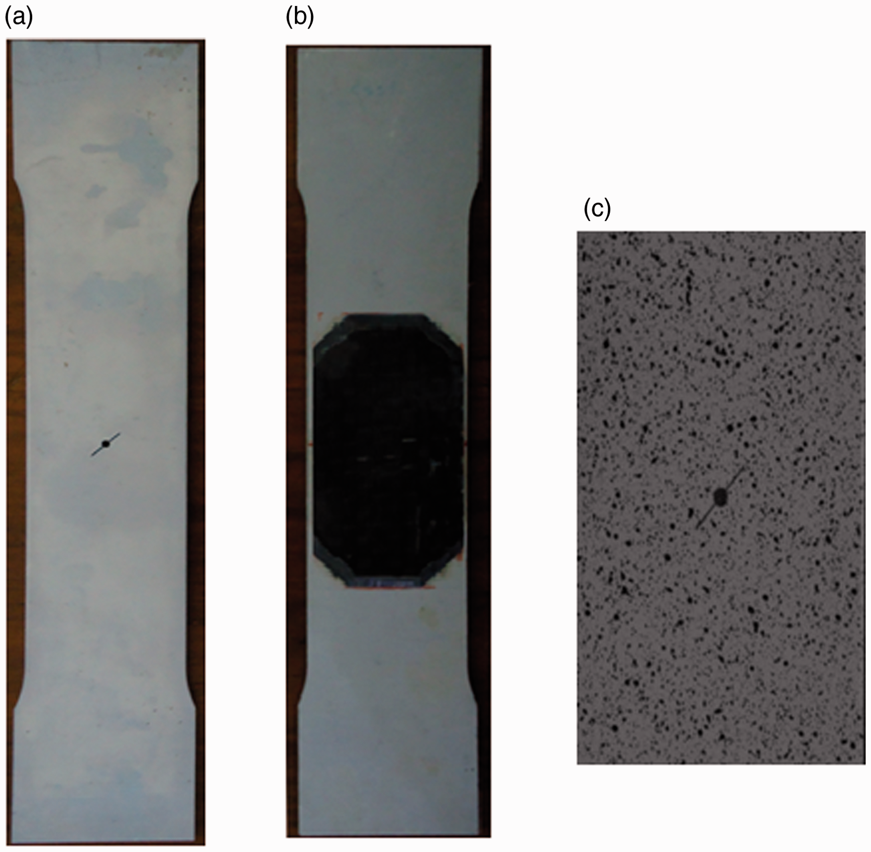
Test setup for 3D DIC study
Figure 6 shows the DIC setup along with the loading equipment used in the present study. The 3D DIC system comprises of a pair of CCD cameras (2448 × 2048 spatial resolution and frame rate of 15 fps), Schneider Xenoplan lenses of 35 mm focal length, a portable computer system fitted with an image acquisition card and a white LED light source of 30 W to ensure adequate image contrast. The DIC setup is from correlated solutions Inc., USA. The specimens are loaded using a computer-controlled MTS Landmark® servo-hydraulic cyclic testing machine of 100 kN capacity. Self-adjusting hydraulic test fixtures are used to grip the specimens. Uniaxial tensile load is applied along the longitudinal direction of the test specimens using displacement control mode with a crosshead speed of 1 mm/min. Initially, after adjusting the focus and aperture of CCD cameras, they are calibrated for each specimens individually using standard grid pattern. Cameras are connected to the mobile workstation laptop and images are grabbed at a predefined rate of three images per second. In this experiment, the camera is placed at a distance of 730 mm from the specimen to achieve a maximum field of view. In order to estimate the shear strain in the adhesive layer, a 2D DIC setup is employed where the CCD camera is fitted with a Tamron lens of 180 mm focal length. As one has to achieve a magnified view of the thin adhesive layer, Tamron lens is preferred as they are macro lens capable of close-up magnification of 1:10 ratio.
Experimental setup involving 3D DIC setup.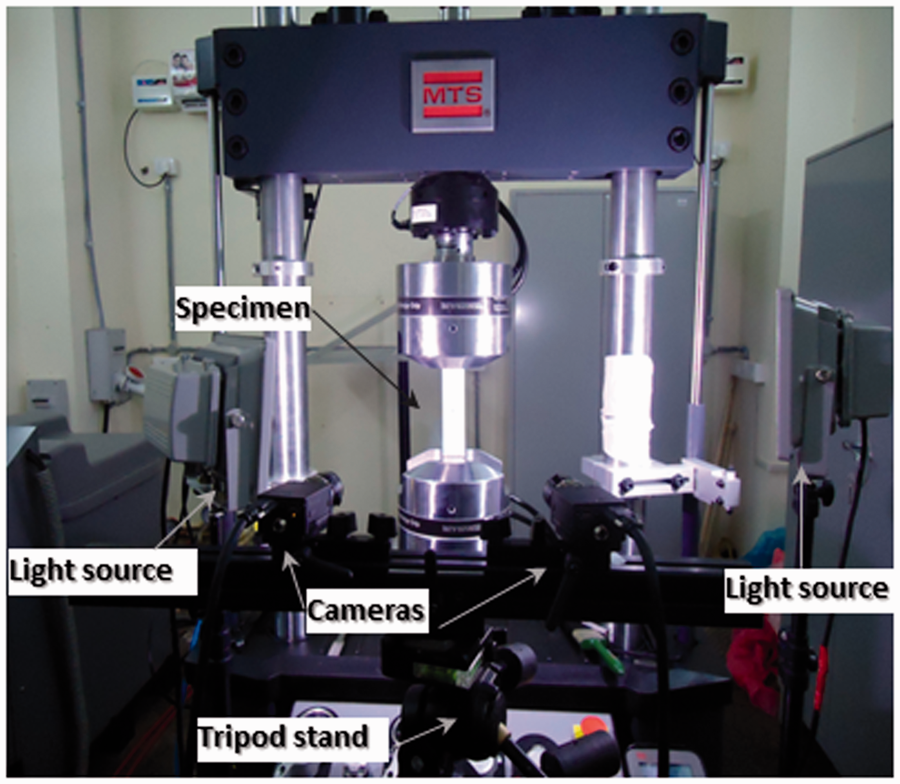
Results and discussion
Parametric optimization involving GA
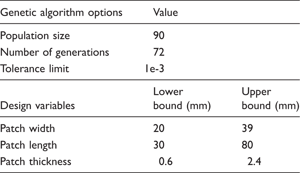
The GA technique is applied to determine the optimal patch dimensions of a patch for repair of an inclined center-cracked panel under mixed mode loading and it is adopted from Refs. 28,29. Here, the optimization is carried out for the double-sided repair panel. The lower and upper bounds of design variables and the GA parameters used in optimization algorithm are summarized in Table 2. The upper and lower bounds are governed by the panel geometry. The multi-objective GA solver in MATLAB is used to solve multi-objective optimization problem and the optimal solution is arrived from the Pareto front as shown in Figure 7(a). Pareto plot shows the trade-off between two objective functions SCF and J-integral value. It is also defined as the set of non-inferior solutions. A non-inferior solution is the one in which an improvement in one objective requires a degradation of another. For example, in Figure 7(a) A and B are clearly non-inferior solution points because an improvement in one objective leads to degradation in the other objective, i.e. at point A, J-integral value is higher whereas at point B, SCF is higher. Therefore, selection of non-inferior solution point would be at point C leading to lower J-value and SCF. In this study, convergence is assumed to be reached when the function tolerance limit of 1 e-3 is reached. Figure 7(b) shows the average spread with the number of generations. In this procedure, each generation is assumed as 90 iterations. From Figure 7(b) one can see that the convergence is achieved after 30 generations and is the same afterwards until it gets terminated. This algorithm has terminated with minimum SCF value of 1.04 and J-value of 0.19 for patch geometry of 38.2 × 78.3 × 2.1 mm3. These optimum dimensions are compared against the composite repair manual system (CRMS) guidelines as mentioned in Appendix 2. From this study, the optimum patch dimensions considered are 38 × 78 × 2.1 mm3. To avoid the severity of the peel stresses occurring at the overlap ends, tapering is provided at the edges with a ratio of 1:20 as mentioned in Ref. 2. The same patch dimension is also kept for the single-sided repair configuration.
Parametric optimization plots: (a) Pareto plot and (b) average spread. Optimization parameters.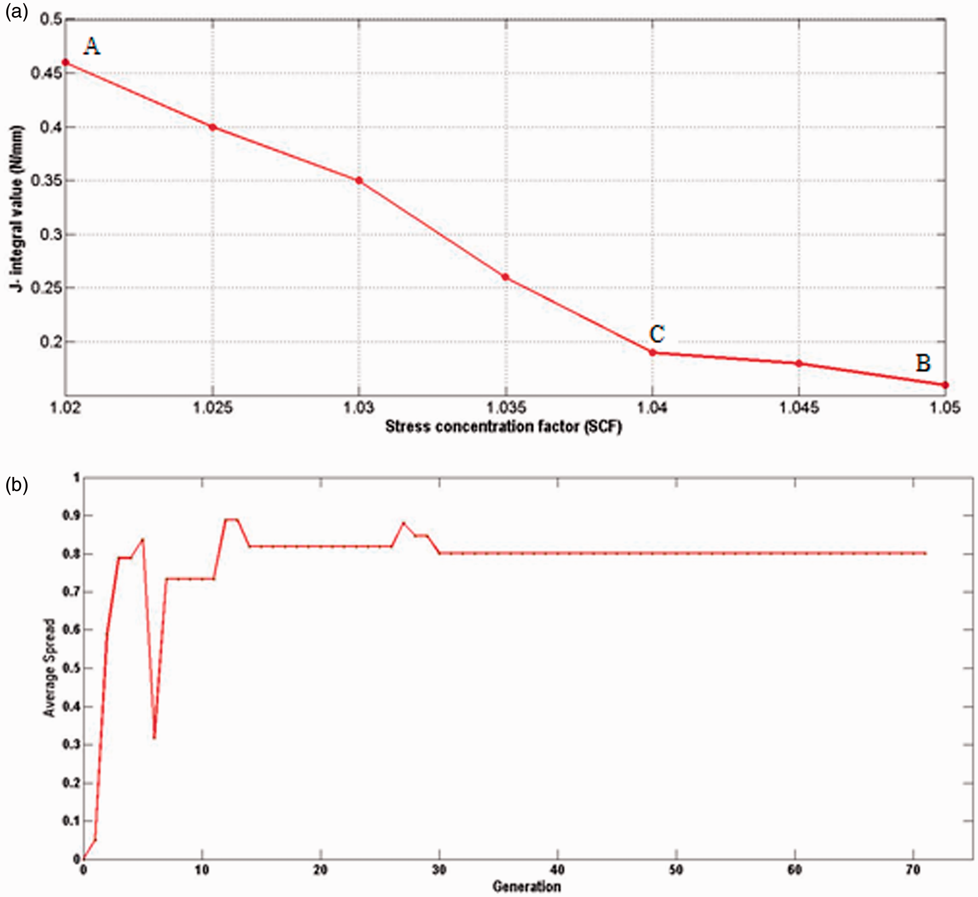
The specimens are fabricated with the aforementioned optimum patch dimensions, and whole field strain analysis is carried out both experimentally and numerically and is discussed in detail in the following sections.
Variation of SIF in repaired panel
SIF variation through the panel thickness for the single- and double-sided patch model is compared with the unrepaired panel in Figure 8. There is a drastic reduction of KI, KII and KIII values of about 70% in case of double-sided repair and the variation is symmetric through the thickness of the panel. In case of single-sided patch, due to existence of out of plane bending, both KI and KIII values are higher at unpatched surface as compared to the patched surface. Also, in the single-sided patch repair, the value of KI at the unpatched surface is more than that of unrepaired value. This is due to linearly increasing bending stress (σy) across the panel thickness arising due to eccentric loading.
11
From Figure 8 it is observed that on overall comparison SIF reduction is highest in the case of double-sided repair and it works very effectively.
SIF variation along crack front obtained using finite element model involving VCCT approach: (a) KI, (b) KII, and(c) KIII.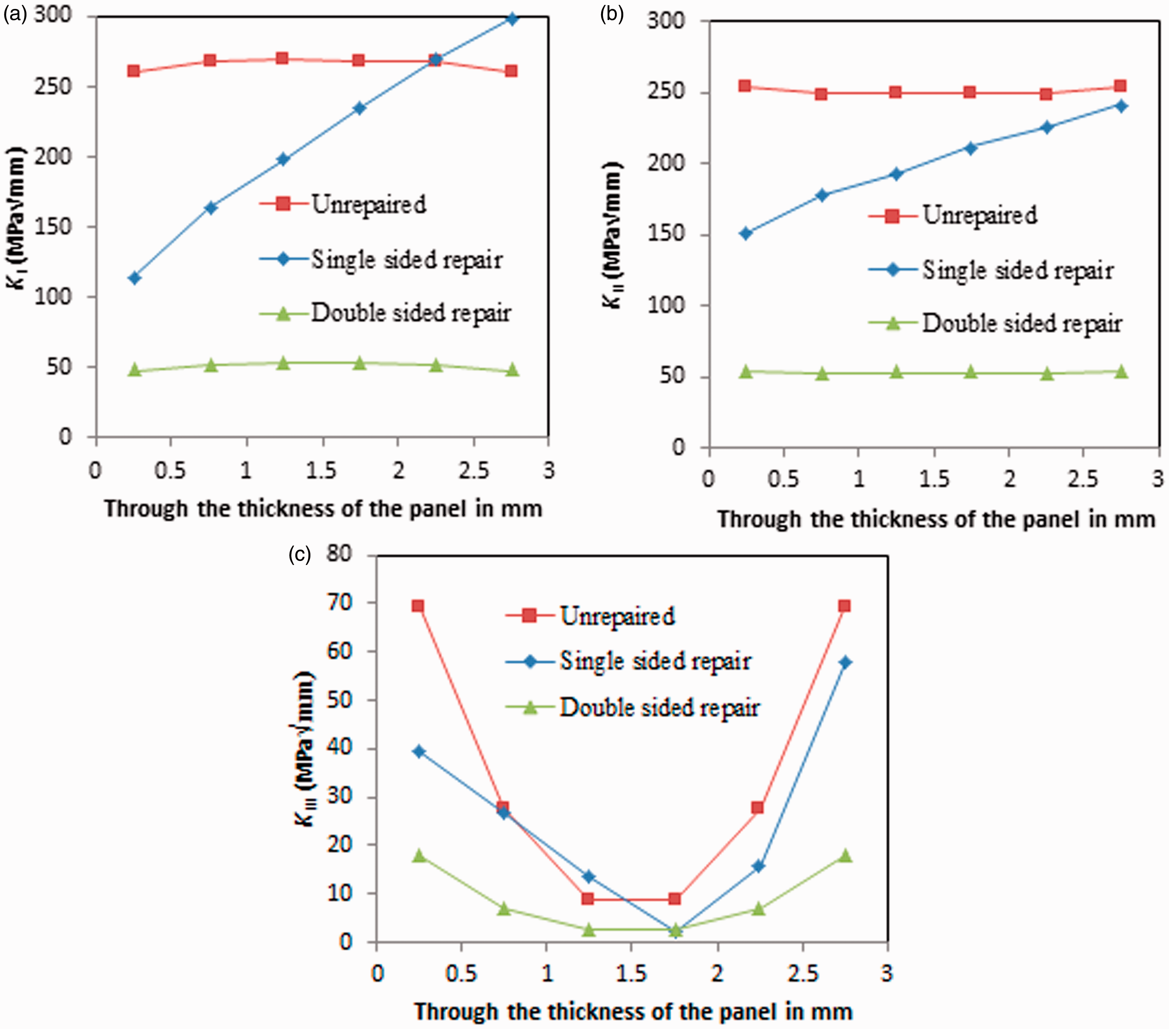
Whole field strain distribution
The behavior of cracked panel subjected to tensile load is studied using 3D-DIC technique. The images acquired by the camera system are post-processed using the available Correlated Solutions Vic-3D software
34
to obtain the whole field displacement and strain field in the vicinity of the crack tip in the case of unrepaired specimen. The region of interest (ROI) for correlation is chosen as 335 × 870 pixels. A subset size of 29 × 29 pixel is selected with a step size of seven pixels for DIC calculations. Figure 9(a) shows the contour plot of ɛyy for cracked panel obtained from DIC at a load of 15 kN. It is evident that as the load increases, crack propagation occurs along a plane perpendicular to the loading direction with increasing load as the crack is inclined. Overall, authors have used the same scale for plotting the strain contour obtained from both DIC and FEA for qualitative comparison. Always the FEA contour scale is adjusted with the DIC scale for all comparative plots. Figure 9(b) shows the whole field strain surrounding the crack tip obtained from FEA. In DIC measurement, the algorithm avoids the data very close to a crack tip as it has a boundary, and precisely one does not get the crack tip strain field. Therefore, Vic-3D software leaves out few pixels close to the boundary and exactly it does not estimate the strain in those pixels. Due to this, one cannot get sharp contours near the crack tip from DIC as compared to FEA plot. On overall basis, the feature of the fringe pattern surrounding the crack tip looks similar for both DIC and FEA strain contour plots under the same scale.
Contour plot of longitudinal strain (ɛyy) over the crack area at a load of 15 kN for unrepaired panel: (a) DIC and (b) FEA.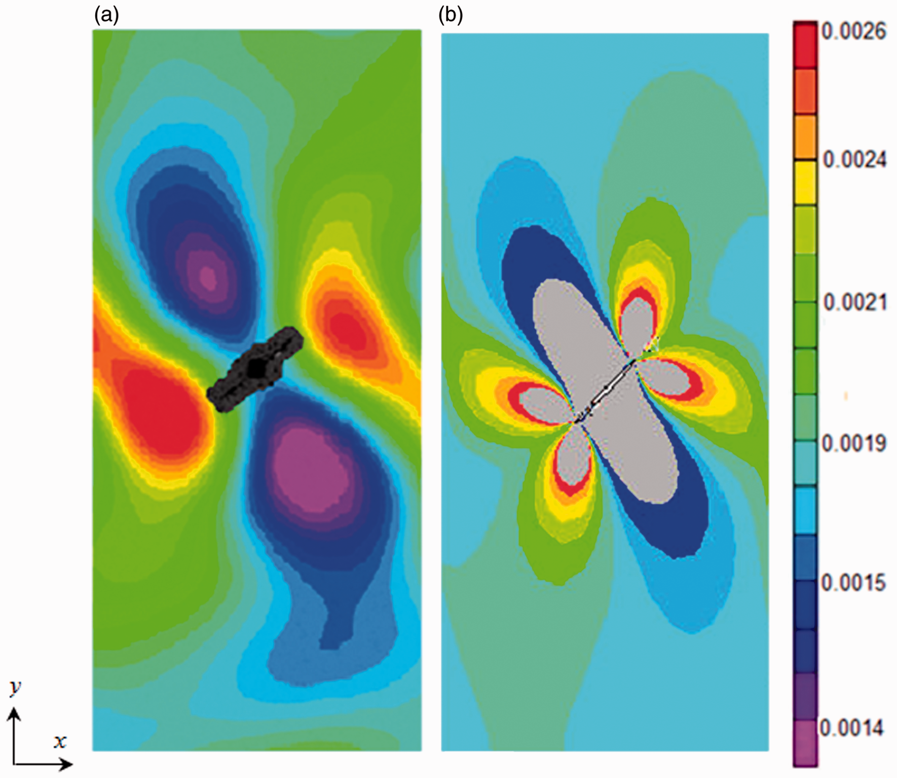
Further, whole field strain analysis over the patched area of single sided repair is studied. The ROI for correlation is chosen as 39 × 109 mm which corresponds to 466 × 1750 pixels. Figure 10 shows the comparison of whole field strain contour obtained from DIC with the FEA result at a load of 15 kN. The maximum value of ɛyy is observed at upper and lower edge of the patch along the y-direction (loading direction) and is lower at the patch center (see Figure 10a). This is because one cannot measure the strain at the crack tip and therefore overlap edge bears the maximum strain due to high stress concentration, leading to patch debonding from the panel as the load increases. Figure 10(b) shows that the whole field ɛyy strain contour from FEA. Here too, the strain values are higher at overlap edges other than the crack tip location. In the contour plots, the patch shape of the specimen and FE model look slightly different because in the case of FE model the tapering is provided by modeling stepped patch, whereas in the experiment the patch edge is tapered with smooth filing operation as mentioned in the previous section. The failure initiates with partial patch debonding at overlap edge followed by the fracture of the panel. On an overall basis, the longitudinal strain contour obtained from DIC and FEA agrees well.
Comparison of whole field strain contour (ɛyy) over the patch area for the single-sided patch repaired panel at a load of 15 kN: (a) DIC and (b) FEA.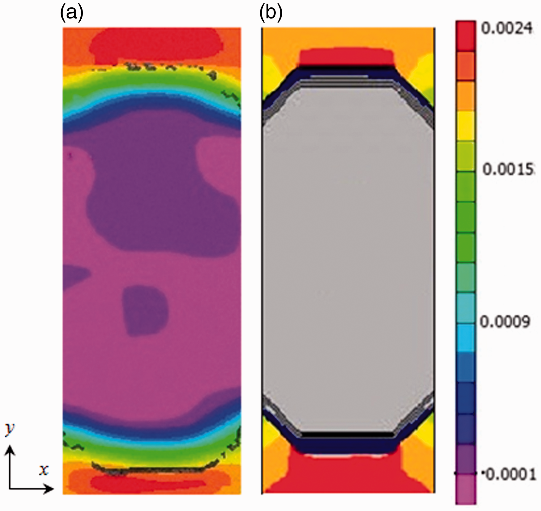
The whole field strain distribution over the patched area of double-sided repair is estimated by taking ROI as 39 mm × 104 mm which corresponds to 458 × 1670 pixels. Contour plots of ɛyy for double-sided repaired panel obtained from DIC and FEA are shown in Figure 11 corresponding to 15 kN load. The contour plot of ɛyy (see Figure 11(a)) is similar to that of single-sided repaired panel. In the DIC plot, a highly straining zone appears at the patch edge as the crack tip strain values cannot be measured. The strain field predicted from FEA and DIC agrees broadly at the contour level. In this case too, the failure initiates with partial patch debonding at the overlap edge followed by complete fracture of the panel which is very similar to the single-sided patch behavior.
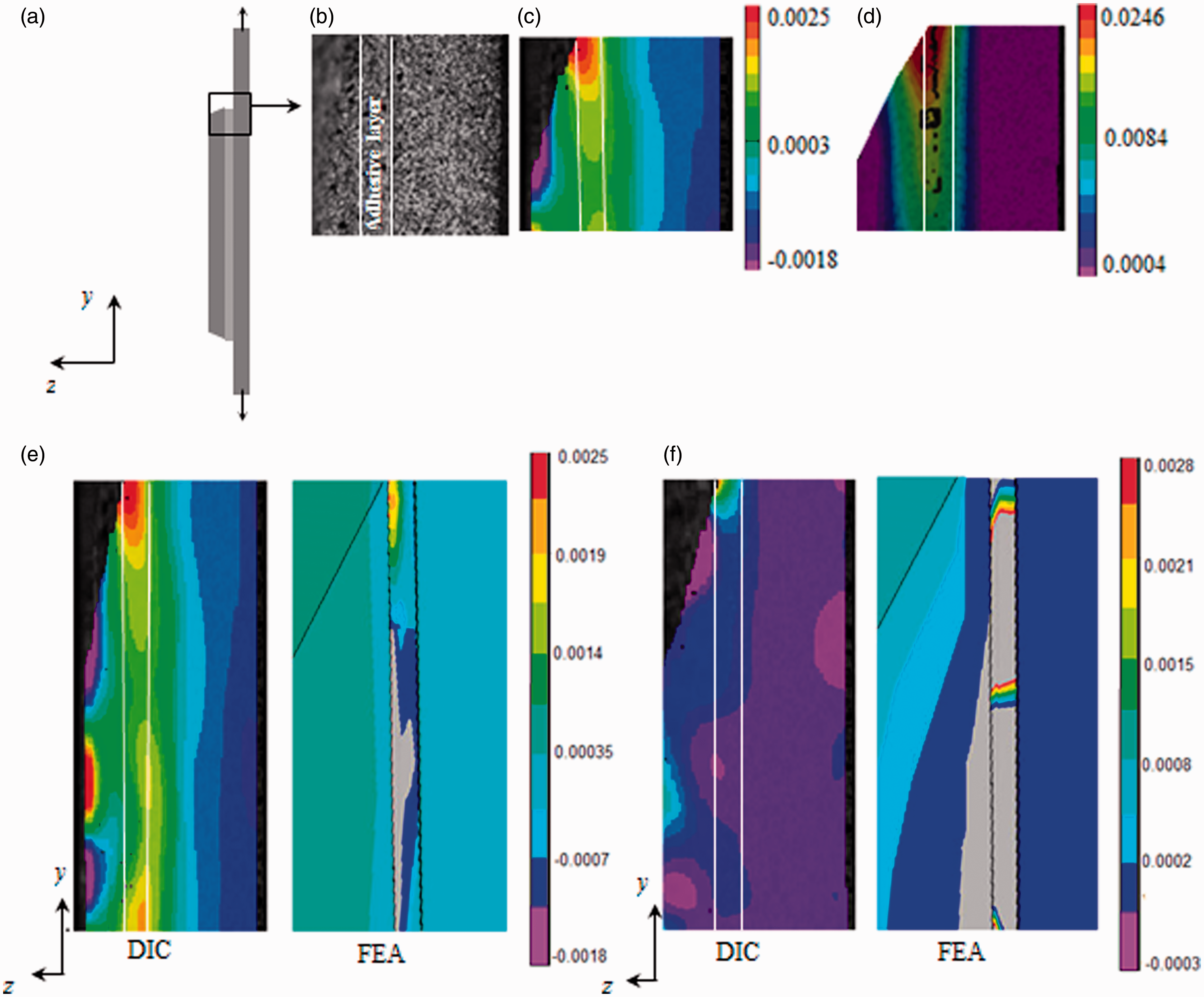
Comparison of whole field strain contour (ɛyy) over the patch area obtained from DIC and FEA for the double-sided patch repaired panel at a load of 15 kN: (a) DIC and (b) FEA. Surface speckle pattern and peel strain distribution in single-sided patch repaired panel: (a) line diagram of setup, (b) Speckle pattern with marked adhesive layer, (c) peel strain (ɛzz) field at 35% of failure load, and (d) peel strain (ɛzz) field at 60% of failure load and comparison of strain contour obtained from DIC and FEA at a load of 15 kN (e) ɛzz (f) ɛyz.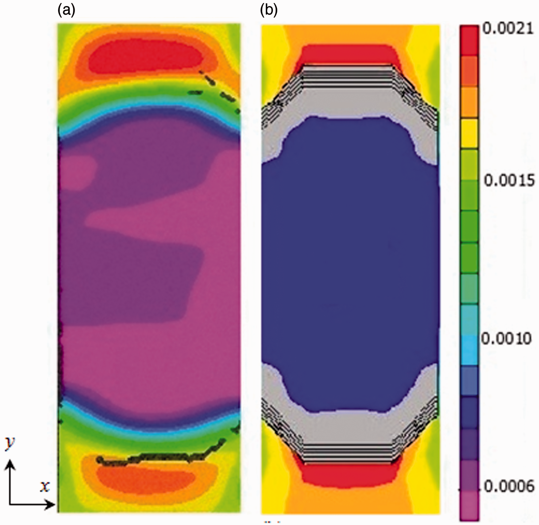
Strain field in the adhesive layer
The average thickness of the adhesive layer is 0.134 mm and is measured using an optical microscope (see Appendix 3). In the repair model, the shear and peel stresses are higher at the edge of the adhesive especially at the interface between adhesive/patch and adhesive/panel. Also, load is transferred by the adhesive layer to the patch over the crack zone by shear deformation. To perform the strain measurement in the adhesive layer using 2D DIC setup, CCD camera is focused on the thickness side of the specimen and it is fitted with a Tamron zoom lens of focal length 180 mm. Figure 12(a) shows the side view of the single-sided repair along with the region of interest, whereas Figure 12(b) shows adhesive layer with speckle pattern and a very fine speckle pattern has been applied for strain measurement in the adhesive layer. Later, correlation solutions Vic 2D software is used to get the adhesive shear strain distribution through the thickness. The observed area is about 6 mm × 14 mm, ROI is 41 × 41 pixels, and the sub-step size is 7 pixels. Figure 12(c) and (d) shows the peel strain contour (ɛzz) at 35% and 60% of failure load. It can be observed that the peel strain is maximum at the patch overlap edge. This high stress concentration near the patch overlap edge leads to patch debonding as the load increases (see Figure 12d). The same experimental setup is adopted for estimation of shear strain (ɛyz) in the adhesive layer.
Figure 12(e) and (f) shows the peel and shear strain (ɛzz and ɛyz) distribution in the adhesive layer of a single-sided repair specimen at a load of 15 kN. From Figure 12(e), it can be observed that the peel strain is maximum at the overlap edge. This high stress concentration near the free edge leads to patch debonding as the load increases. Figure 12(f) shows the shear strain variation and it is evident that the maximum strain is located at the patch overlap edge between the adhesive–patch interface. This shear strain concentration is due to abrupt change in geometry at the patch end. For qualitative comparison purposes, the peel and shear strain field in the adhesive layer obtained from FEA is also shown. The shear strain concentration also happens at the interface between the adhesive and patch, thereby confirming DIC prediction. It can also be observed that shear strain is maximum at the overlap edge and gradually reduces as the distance from the overlap edge increases. One can conclude that the shear and peel strain concentrate near the overlap edge of the adhesive resulting in patch debonding.
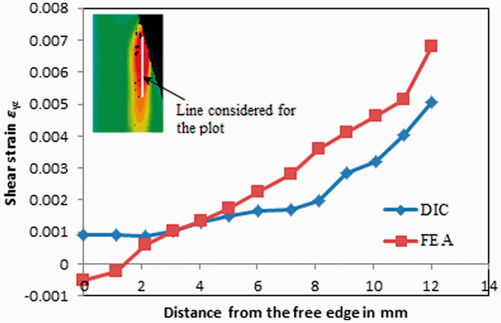
Generally, in the case of adhesively bonded patch repair, the damage initiates from the adhesive–panel interface due to adhesive layer failure. The strain field of ɛzz and ɛyz obtained in case of double-sided repair at 15 kN load is shown in Figure 13. It could be observed that a high peel strain occurs in the adhesive layer closer to inner side of adhesive/panel interface and subsequently the patch peels off from the panel as the load level increases. Shear strain distribution in the adhesive layer is shown in Figure 13(b). Looking at the DIC plot, one can see that a maximum value occurs at the right side overlap edge. This indicates that patch debonding initiates from the top in the right side patch and from the bottom in the left side patch. Due to high shear strain levels in the adhesive layer the load transfer capability of the adhesive decreases leading to patch debonding and then load is directly taken by the cracked panel resulting in complete fracture at higher load level. From Figure 13 it is understood that strain contour plots (ɛzz and ɛyz) obtained from FEA overall matches with DIC contour. Figure 14 shows line plot of the shear strain variation along the adhesive–patch interface edge. The shear strain decreases as one moves away from the overlap edge and a better correlation exists between DIC and FEA prediction, thereby confirming the accuracy of FEA analysis.
Comparative plot of strain along adhesive–patch interface involving both DIC and FEA at a load of 15 kN for double-sided patch repaired panel. Variation of shear strain along adhesive–patch interface involving both DIC and FEA at a load of 15 kN for double-sided repaired panel.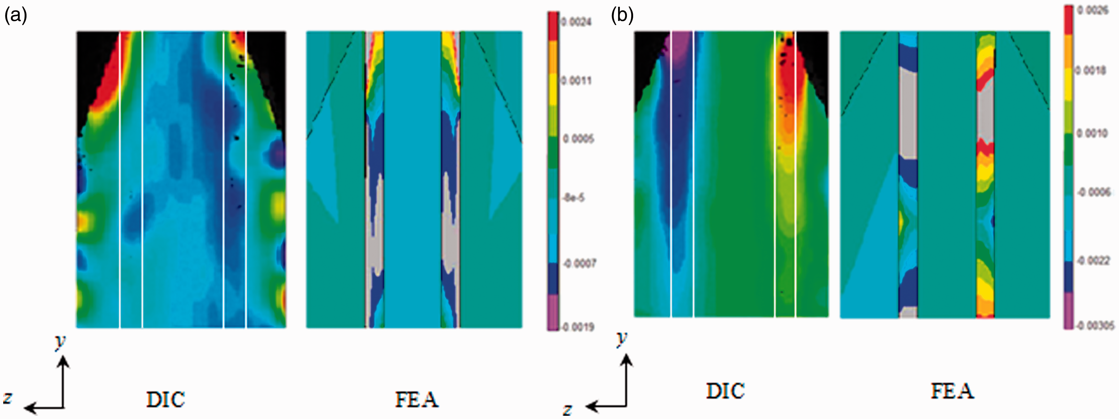
The failure mechanism observed in cracked as well as single- and double-sided patch repaired panel is shown in Figure 15. It can be observed from figure that the crack propagates along a plane perpendicular to the loading direction as the load increases (see Figure 15a). In the case of repaired panel due to shear and peel strain concentration, adhesive layer near the patch overlap edge results in partial patch debonding followed by the fracture of the panel similar to the cracked panel (see Figure 15(b) and (c)). The partial debonding happens due to adhesive layer failure.
Fracture mechanism: (a) cracked panel, (b) single-sided repaired panel, and (c) double-sided repaired panel.
Experimental performance of unrepaired and repaired panel
The key interest in the composite repair system is the stress transfer from crack front to the patch overlap edge. The variation of longitudinal strain ɛyy for cracked and repaired specimens is plotted with respect to the applied stress shown in Figure 16. From Figure16 it can be observed that the reduction in strain due to repair is relatively small. This is probably due to the small stiffness of the adhesive layer compared to that of the panel and patch. Araldite 2011 adhesive is of intermediate grade with higher toughness
33
and Young’s modulus of adhesive material is 60–75 times smaller than the panel and patch material. The effectiveness of patch also depends on the stiffness ratio which is nothing but the ratio of patch stiffness to the panel stiffness (Eptp/Ests). Normally, the recommended stiffness ratio ranges from 1 to 1.6 as mentioned in Ref. 5. In this study, the stiffness ratio is 0.9 and hence much stiffening is not there and it could be improved if the patch thickness is increased.
Longitudinal stress (σyy) vs longitudinal strain (ɛyy) obtained from DIC at a location far away from the crack zone.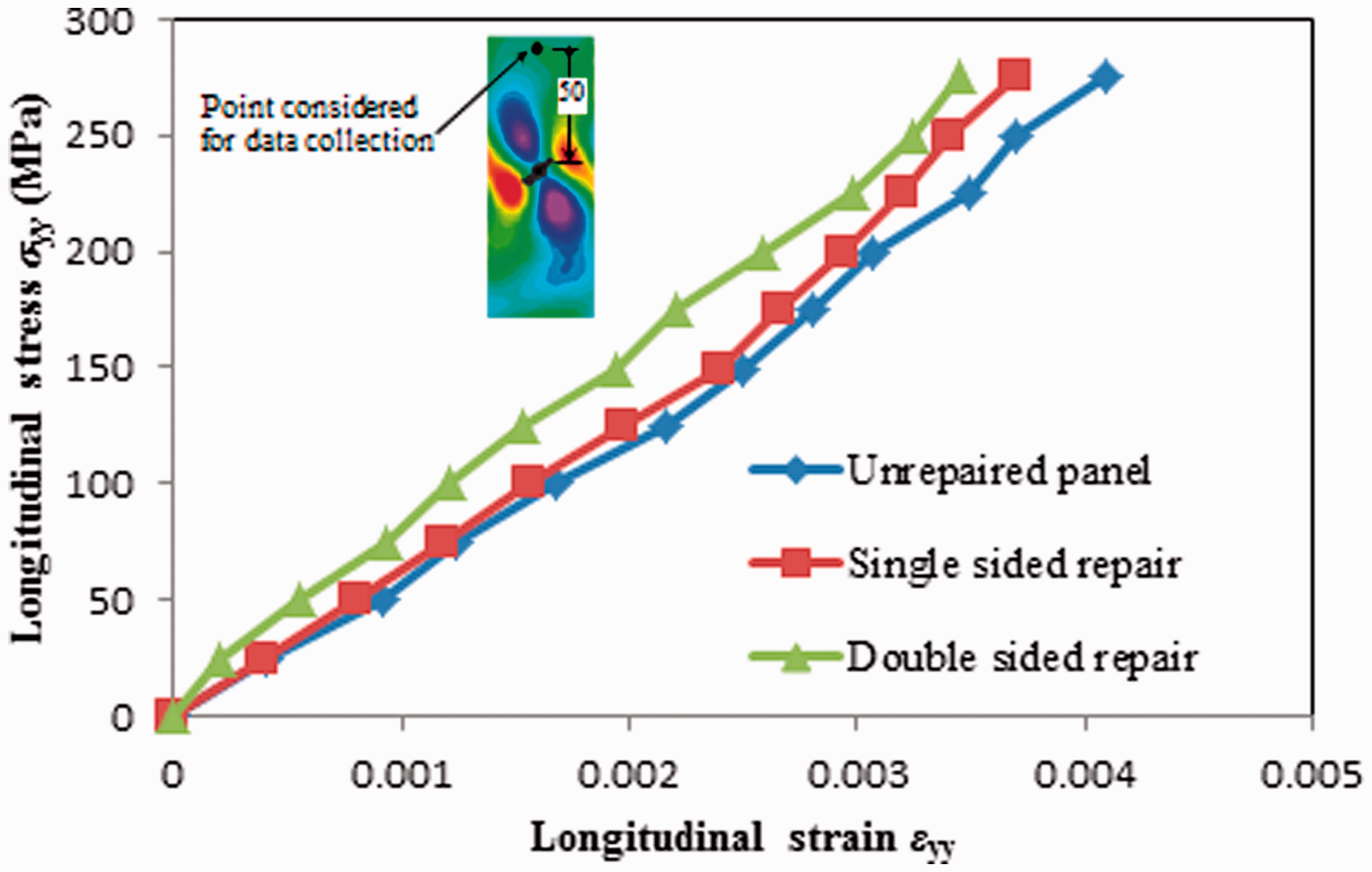
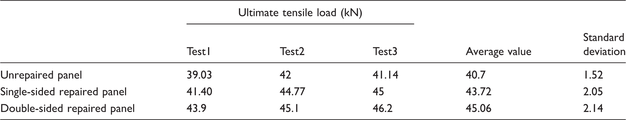
To compare the strength of the unrepaired and repaired structure, load versus displacement curve for all the three cases is plotted in Figure 17 and they are obtained from the experiment. From Figure 17, it can be confirmed that the stiffness of double-sided repaired panel is the highest. The failure strength is estimated as failure load upon gross cross-sectional area of the specimens. On that basis, for the unrepaired panel the failure strength is 316.66 MPa, whereas for single- and double-sided repaired panels it is 341.6 MPa and 383.34 MPa, respectively. Table 3 shows the standard deviation of three successive tests carried out for all the configurations. From the Table 3 it is clear that ultimate load-carrying capacity and the strength of the double-sided repaired panel are higher than both single and unrepaired panel, and therefore it is generally preferred for repair applications.
Load vs displacement obtained from MTS test machine. Standard deviation in peak load for three successive test results.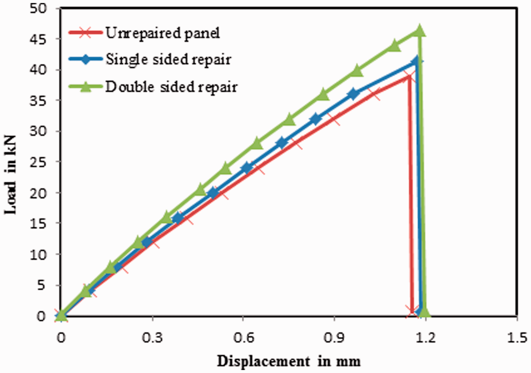
The strain field obtained from DIC shows us the critical location leading to damage initiation and further helps us in predicting the damage initiation load. DIC is also very useful for whole field strain measurement and it is useful for comparing the FEA prediction. The important aspect of DIC utilization is proved for adhesive layer strain measuring where the thickness is very small.
Challenges in composite patch repair applied to new generation aircrafts
This work is very much relevant to the new generation of aircraft, e.g. Boeing 787 or A350, which are commercial aircrafts with composite wings and fuselage. This repair technology can easily be extended to repair of damaged composite panels. Depending on the type and location of the damage, structural composite repair can be executed through resin injection or externally bonded or scarf-based repair. 4 The first technique of resin injection repair is a temporary measure to stop the spreading of damage. The second technique of externally bonded repair can provide a permanent restoration of structural strength, but one cannot get the smooth surface and it is useful for repair of secondary load-bearing structures. The third technique of scarf repair can offer structural strength as well as a flush surface, and thus it is very useful for external skin panels. It is primarily used for repair of primary load bearing structures where the thickness is large. In scarf repair, each repair ply overlaps the damaged ply by giving a straighter, stronger load path.3,4,35 Performing scarf repair is not easy and it requires greater skill set. A widespread of research has been carried out on experimental and numerical investigations of externally bonded patch repair applied to composite panels with open hole configuration.25,29,36–38 It is very similar to the repair of metal panels, and damage in repaired composite panel involves debonding of composite patch from the panel followed by complete failure of the panel under different failure modes such as delamination, matrix cracking, fiber pull out, and fiber splitting.25,38 Here too, the adhesive is the weakest link and its failure happens at the overlap edge which leads to overall failure.
Conclusion
In this work, both DIC- and FEA-based studies are carried out to evaluate the performance of bonded patch repair of inclined center-cracked aluminium panel. Initially, an optimum patch dimension for the given inclined cracked panel is arrived using GA-based optimization technique in conjunction with FEA. Following the optimization, the study on cracked and repaired panel is carried out using 3D DIC setup. Full field strain variation over the surface of the panel as well as patch is estimated. It is found that highly localized strains always develop around the patch overlap edge and the crack propagation is always perpendicular to the loading direction. To make the study complete, both shear and peel strain distribution in the adhesive layer is also predicted using 2D DIC setup. From the DIC estimation, one can conclude that the shear strain concentrates in the adhesive layer at the patch overlap edge resulting in adhesive layer failure leading to partial patch debonding at overlap edge. This results in reduction of load transfer capability of the patch leading to complete fracture of the panel at higher loads. For both the repaired cases, partial debonding of the patch followed by complete failure of the panel is observed. Full field strain variations obtained from the experiment are compared with the finite element results and they are found to be in agreement. The failure strength of the double-sided repaired panel is found to be more than that of the single-sided and unrepaired panel. Also, SIF reduction in case of double-sided repair is highest and therefore it is recommended for bonded patch repair applications. The utility of DIC as an accurate experimental technique for whole field strain prediction in repair applications is established and it is found very useful to understand the mechanics of adhesively bonded patch repair especially for adhesive shear strain measurements where the layer is too thin.
Footnotes
Funding
This research received no specific grant from any funding agency in the public, commercial, or not-for-profit sectors.
Conflict of Interest
None declared.
Acknowledgements
The author’s wishes to thank Mr Jagadeesan and Mr Praveen kumar, central workshop, IIT Hyderabad for helping us in preparing CFRP patch. Also we would like to thank Mr Mohammed Kashfuddoja, Research scholar, Engineering optics lab for carrying out adhesive shear strain measurement experiment.