
Abstract
Curved section is regarded as the weak point of composite structures because of the delamination caused by the stress concentration. In the present work, L-shaped specimens made of randomly oriented short fiber-reinforced polypropylene were prepared to investigate the effect of the radius of the curved section of composite structures on the strength and the damage modes. The results of tensile tests and finite element analysis indicated that the radius greatly affects on the stress distribution and the damage modes, and showed good agreement with former researches using different composites. The strengths of the materials were extrapolated from the results of tensile tests and finite element analysis in this research. Finally, allowable radii of the curved section of the composite structures of two kinds of materials were given respectively.
Introduction
Carbon fiber-reinforced thermoplastics (CFRTP) is considered to be promising ultra-lightweight material for automotive manufacturers not only because it can be applied in the special automobiles to realize extremely driving performance but also because it can improve the energy efficiency of mass-production vehicles to mitigate the global oil consumption and CO2 emission. 1 To ensure the application of CFRTP on mass production, we need to develop comprehensive knowledge about the mechanical properties of the CFRTP materials, parts, and the structures.
The researches on mechanical properties of randomly oriented short carbon fiber-reinforced thermoplastics (SCFRTP) were started from 1990s, among which the theoretical approaches to calculate the tensile properties were investigated by Fu et al.2–4 For most CFRTP, the fibers oriented in-plane quasi-isotropic, so the through-thickness strength can be relatively low compared with the in-plane strength, and therefore even small tensile stress in the through-thickness direction is enough to cause composite failure by delamination.5–7 A lot of trials have been conducted to measure and predict the interlaminar tensile strength and delamination performance of composites.5–27 Because the stress concentration is easy to occur at the curved sections of the composite structures, fractures such as delamination probably start from the curved section. Because the curved sections are considered to be the weak point of the composites, a lot of efforts have been made to conduct the experimental and theoretical studies of stress distributions, damage modes, and mechanical models on curved composite specimens.6–8,10–14,20–23,28–36 Among the researches of composites structures, the I-shaped,28,29,31,34 C-shaped20,21,30 and L-shaped,6,13,22,24,32,33 are considered as the main shapes for industrial applications. The L-shaped specimens were regarded as representative specimens not only for the investigation of damage modes of composites but also to evaluate the interlaminar tensile strength of the material.
However, the L-shaped composites in the former researches were mainly unidirectional/quasi-isotropic laminates and woven fabrics,6,13,32,33 and little attention has been devoted to the randomly oriented SCFRTP. Because the randomly oriented SCFRTP are considered as one of the promising materials for mass-production vehicles, since they are suitable for making complex shape parts, 1 we need to conduct more studies on the mechanical properties and the behavior of the curved parts of these materials under loading.
The objective of the present work was to investigate the effects of the curvature of L-shaped specimens of SCFRTP on mechanical properties and damage modes. Two kinds of randomly oriented short fiber-reinforced polypropylene (PP) were used in this study. L-shaped specimens were formed in different radii. Tensile test and finite element method (FEM) were conducted to investigate the effect of radius, the damage modes, and the stress distributions. The results of tensile tests and FEM indicated that the radius greatly affects the stress distribution and the damage modes of the specimens, and showed great agreement with former researches using graphite-epoxy laminates L-shaped specimens.13,22 The strengths of the materials were extrapolated according to the results of the tensile tests and the FEM. Allowable radii of the curved sections of two kinds of SCFRTP were given to avoid delamination in this research.
Materials and methods
Materials
Two kinds of materials, which are produced for the mass production vehicles, were used in this research (Figure 1). One is CMT (carbon fiber mats-reinforced thermoplastics), which is composed of PP and CF papers (randomly orientated carbon fiber monofilaments). This material is suitable for making complex shape parts, but the carbon fiber volume fraction Appearance of CMT (a) and CTT (b).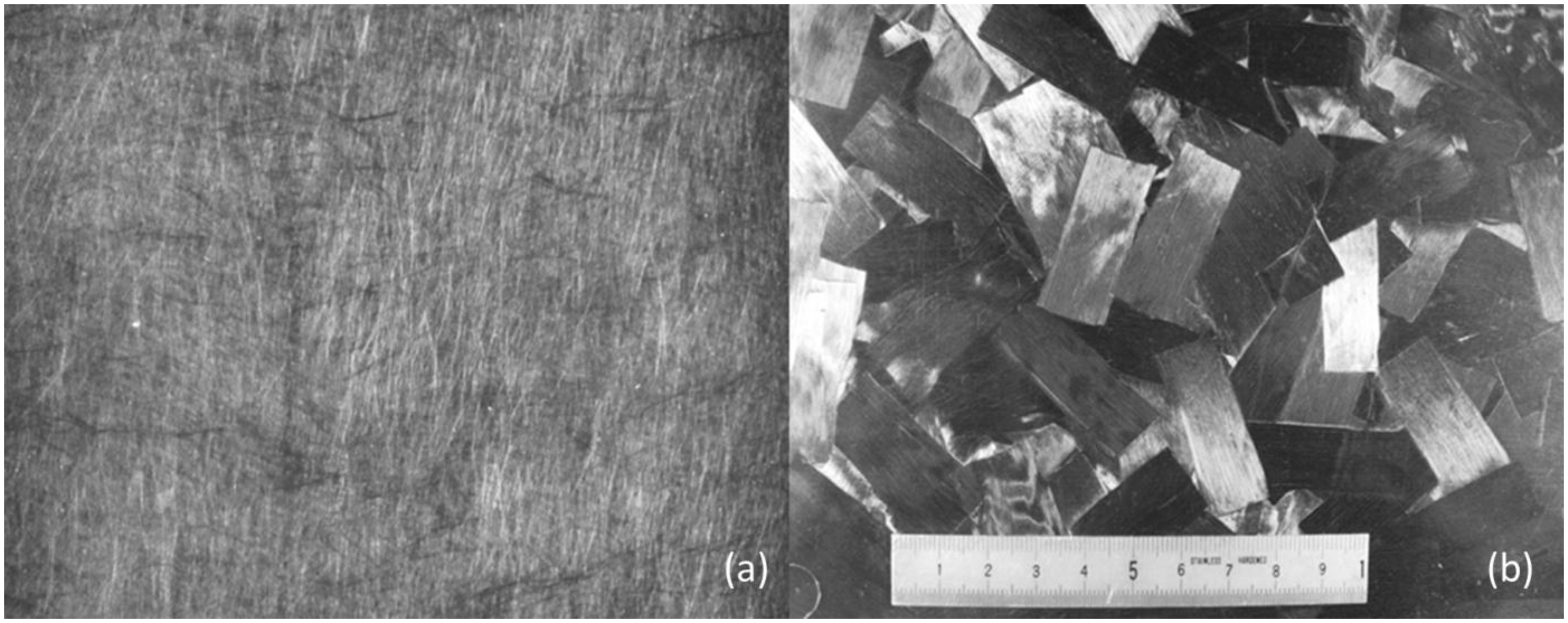
The other material is CTT (chopped carbon fiber tape-reinforced thermoplastics), which is composed of randomly orientated cut CF/PP unidirectional prepreg tapes. The cut tapes size is 35 mm along the fiber direction and 15 mm in width. Because the fibers were impregnated before material molding, the CTT is good at flow molding for making complex shape parts. Additionally, the
The most apparent difference between CMT and CTT is the carbon fiber impregnation rate before the molding process. CMT is composed with the unimpregnated CF papers before the molding while the CTT is composed with pre-impregnated tapes.
The CMT material is provided by TORAY INDUSTRIES, INC, and the CTT is provided by MITSUBISHI RAYON Co., Ltd and TOYOBO CO., LTD.
Specimens
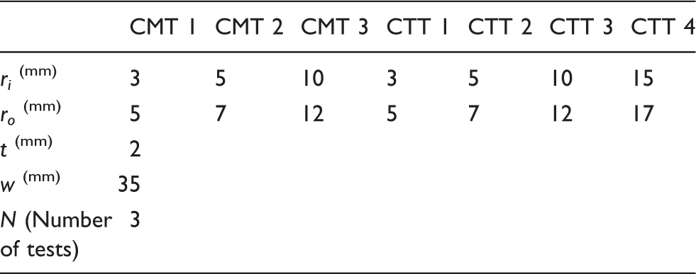
The 90°-bent L-shaped CF/PP specimens were manufactured by heat-and-cool pressing molding, which is one of the dominant molding techniques. Through the molding process, the materials were cut in 35 mm of the width and then heated up to 220℃ by infrared heater, and simultaneously the L-shaped molds were individually heated to 150℃. Then, the material was pressed under 10MPa pressure added by hydraulic-controlled pressing machine and cooled down to 85℃. The molding process is shown in Figure 2. Three kinds of specimens of CMT material and four kinds of CTT material with different radii were perpared. The size of specimens was set the same, i.e. width w = 35 mm and thickness t = 2 mm. The detailed dimensions of the specimens are shown in Table 1. All the specimens were checked by CT-scanning to ensure that no voids and internal damages existed.
Molding processes of the specimens. Specimens types and dimensions.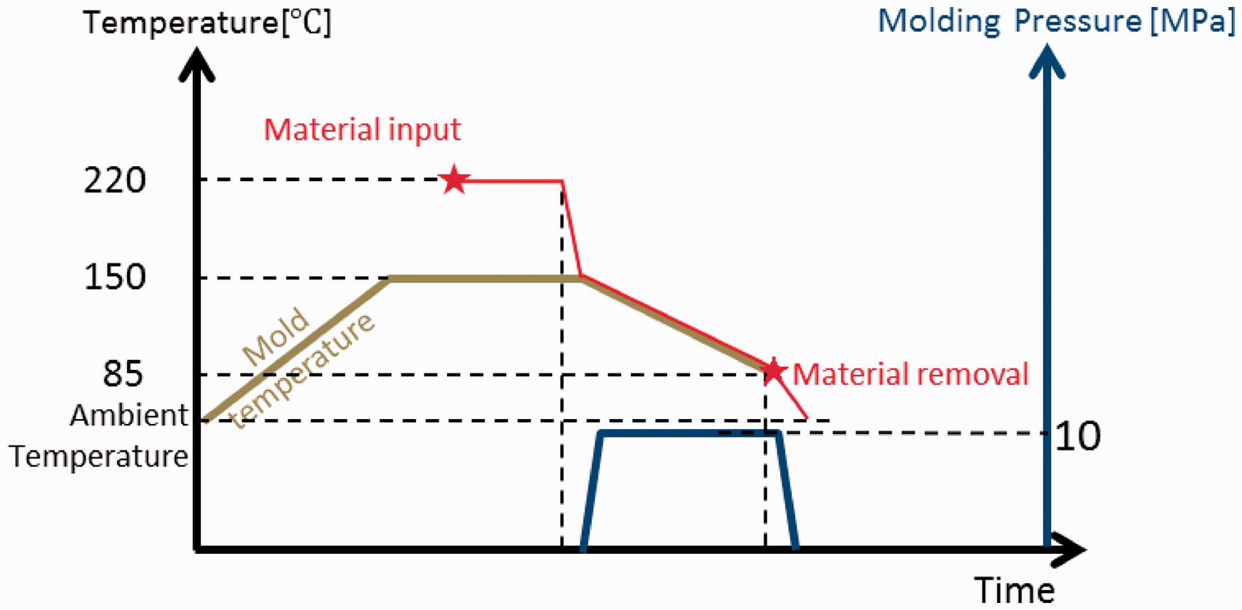
Experimental procedure
Schematics of the L-shaped tensile test is illustrated in Figure 3. Attached to each arm of the specimens was a hinged loading mechanism that was held by the grips of a tensile testing machine. The load cell was set to 5 kN with a measuring accuracy of ±0.5%. The tensile displacement rate was set at the speed of 1.0 mm/min during the loading process. Loads and displacements were recorded digitally by the testing machine until the failure occurred on the specimen.
Schematics of L-shaped tensile test specimen.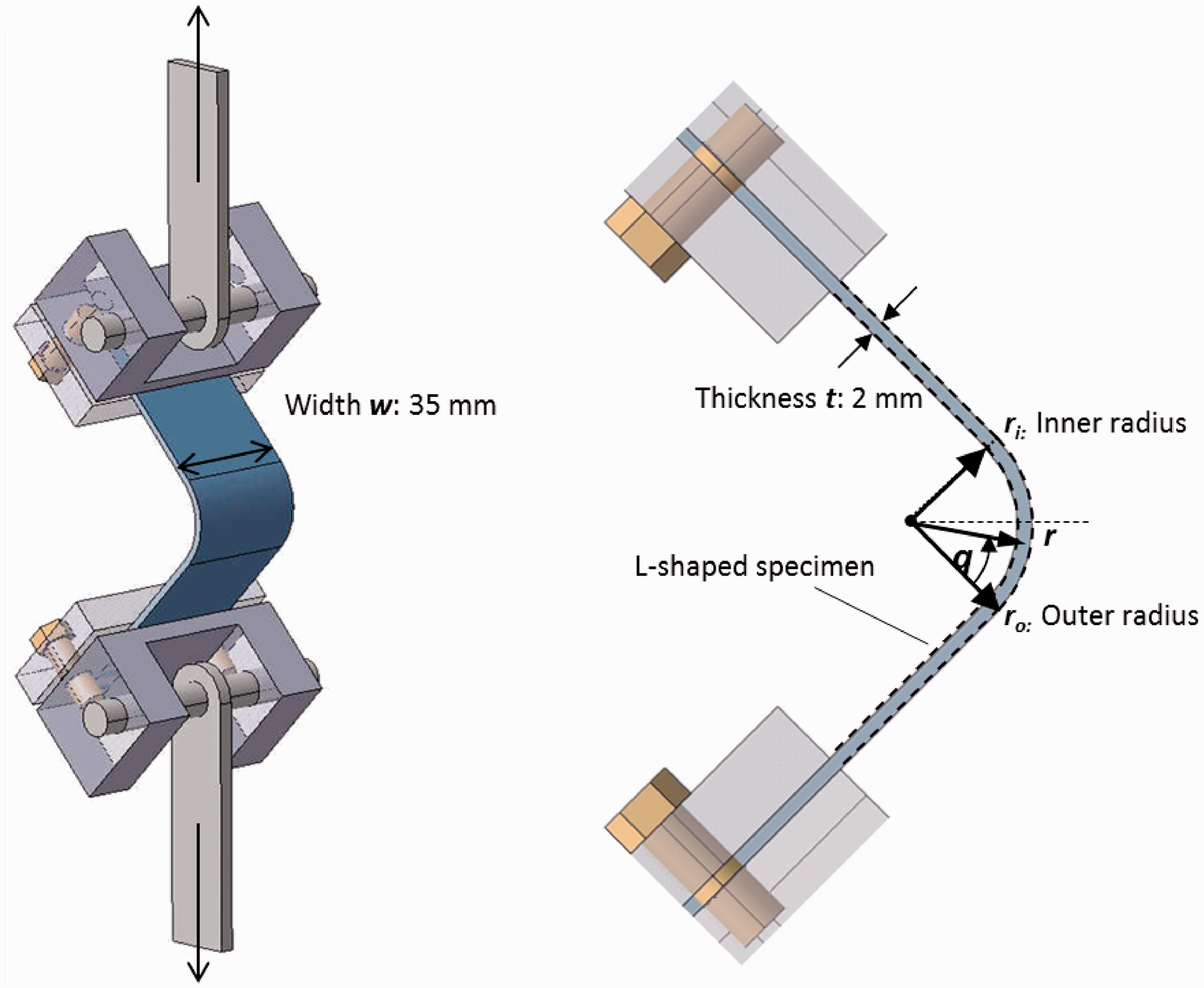
Finite element method
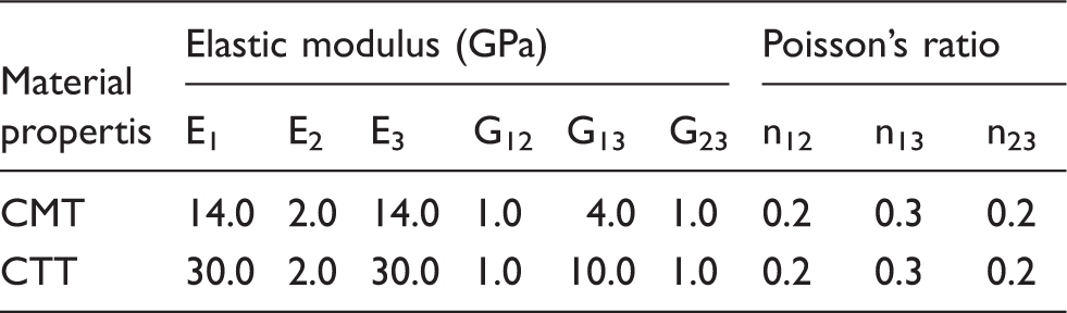
A 2D finite-element model was used on the curved beam specimen to verify the relationship between load and displacement well as to analyze the stress distribution in the curved section of the CF/PP. Only a half size model of the bending test specimen was needed because of the symmetric geometry; the normal direction of the symmetry plane was constrained in the y direction. The specimen was fixed on both sides of the contact face of the loading fixture, and the loading was added to the fixture at a rotation free hinge (Figure 4). ABAQUS 6.11 was used to support the analysis, and material directions 1, 2, and 3 were determined as illustrated in Figure 4. Direction 1 was parallel to the longitudinal direction of the beam; direction 2 was parallel to the thickness direction of the beam, in other words, perpendicular to the longitudinal direction; and direction 3 was perpendicular to planes 1–2. The material properties, respectively, along directions 1, 2, and 3 were determined by the experimental data and given by the corporations provided the materials as indicated in Table 2. All elements were four-nodded quadrilateral with 20 elements in the thickness direction of the specimen model, and the influence of nonlinearity was considered as well due to deformation that occurred during the test.
Finite-element model. Materials parameter settings.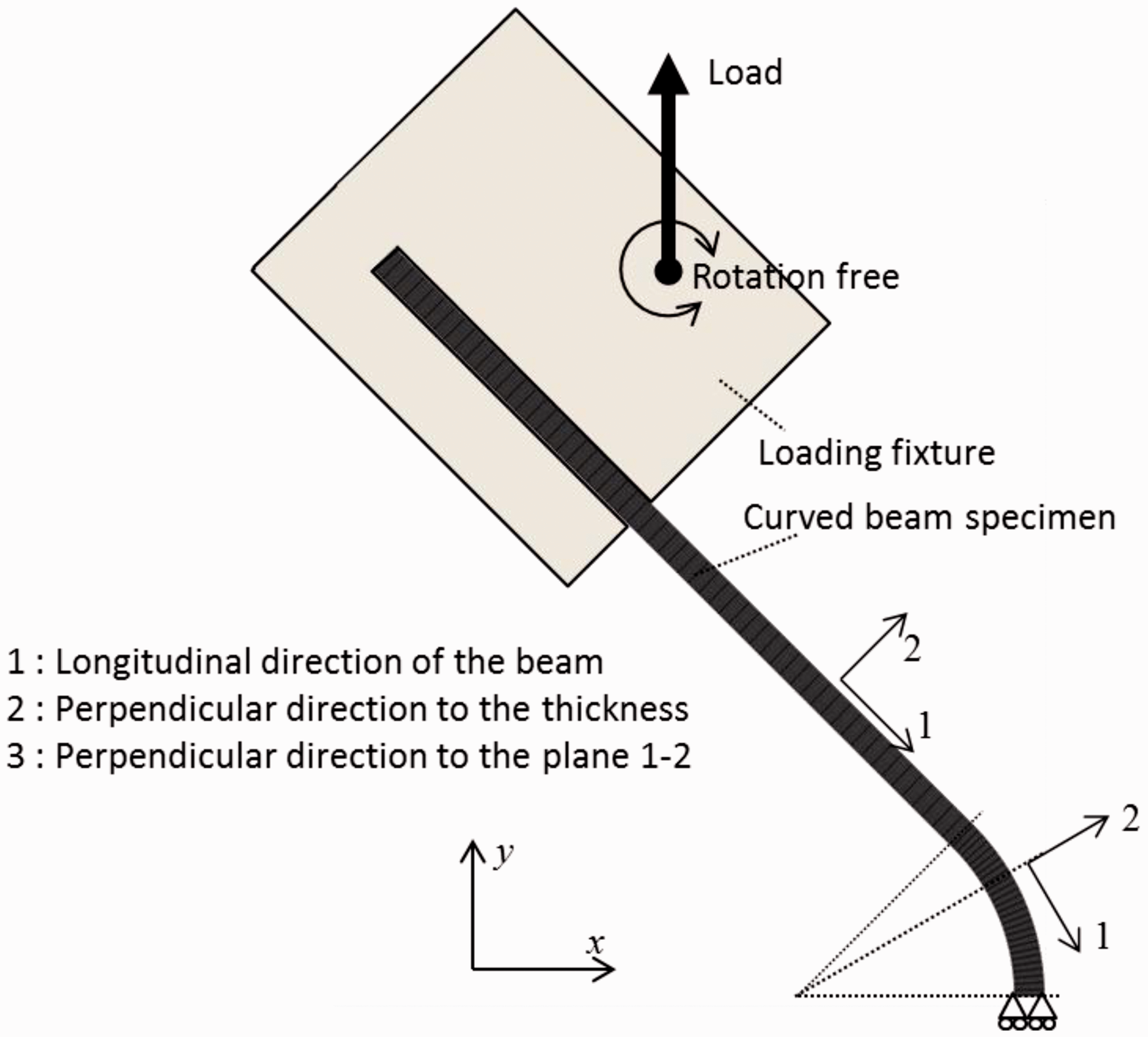
Results
Tensile test
Tensile tests for L-shaped CMT and CTT specimens with different radii were conducted, and the load–displacement curves of the specimens were recorded till the specimens failed.
From the load–displacement curves of CMT specimens illustrated in Figure 5, the individual differences between the three specimens with same radius are small. Moreover, the differences of specimens curve slopes with different radii were small. The failure that occurred in CMT specimens were totally shown as brittle fracture and the curves also exhibited a sudden vertical drop after a smooth growth. The maximum loading force demonstrates a positive correlation to the radius of the specimens.
Load–displacement curves of CMT specimens.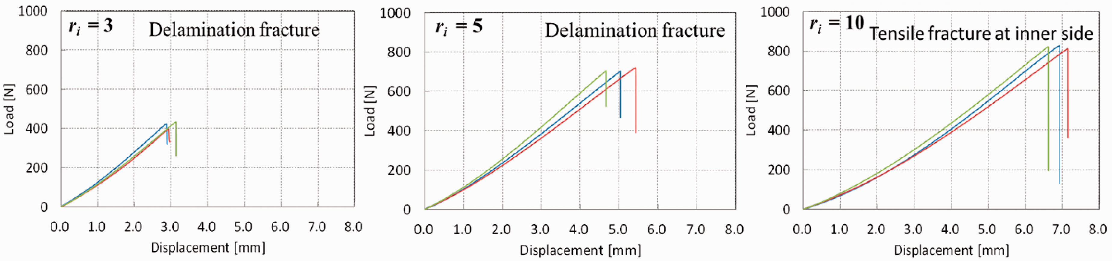
In comparison, the load–displacement curves of CTT specimens (Figure 6) indicated that the individual differences of the curves of specimens in same radius were bigger than the CMT specimens. Furthermore, the average curve slopes were different with different radii, as the slopes expressed an increasing trend with the increase of specimen radius. The failure of CTT specimens showed as ductile fracture on the curves; the load–displacement curves of CTT specimens showed an inflection point and nonlinear growth after the initial smooth growth, and the nonlinear growth of the curves showed great individual differences. Same as in CMT specimens, a positive correlation between the maximum loading force and the radius of specimens was demonstrated in CTT specimens.
Load–displacement curves of CTT specimens.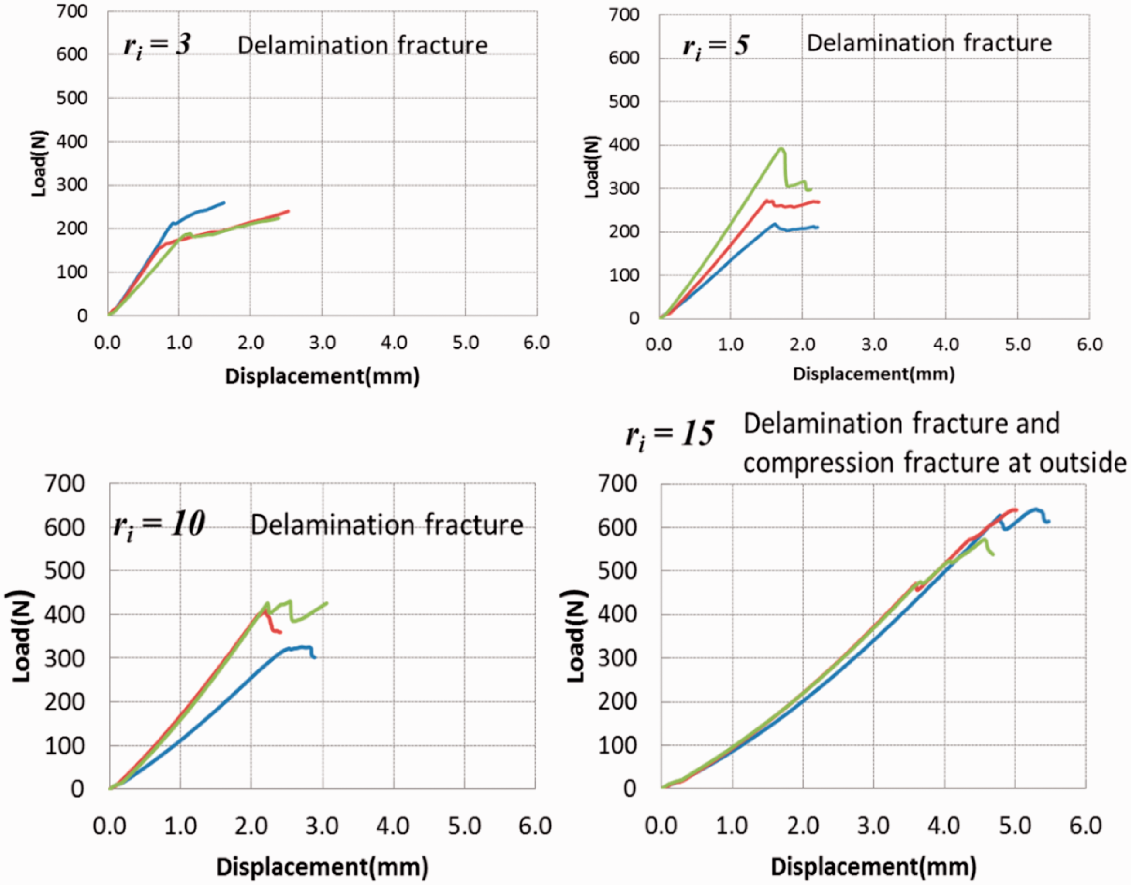
Three different damage modes indicating the delamination, tensile fracture on the inner side of the curved section, and the compressive failure on the outside of the curved section occurred in the tensile tests (Figure 7). For CMT specimens, delamination fracture occurred on the curved section of the specimens with View of fracture modes. Delamination (a). Tensile fracture on the inner side of curved section (b). Compressive fracture on the outer side of curved section (c).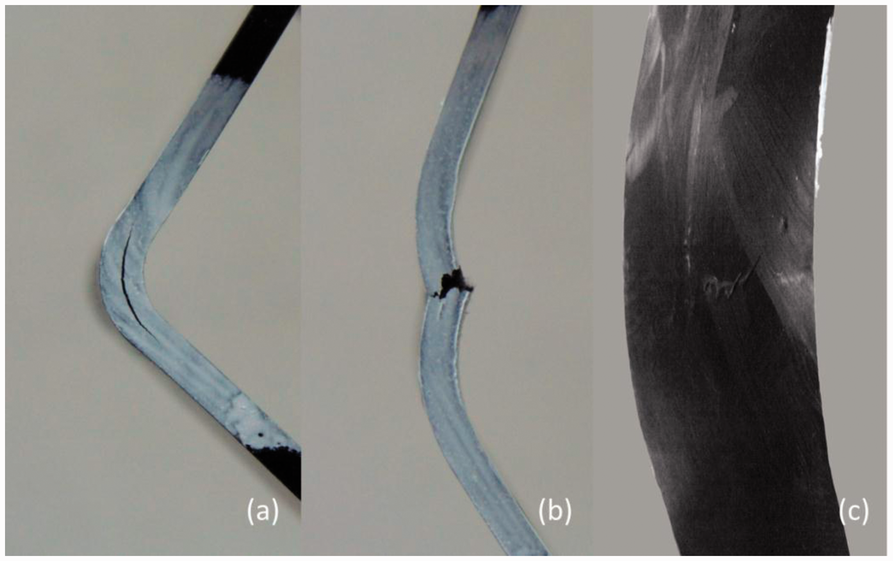
FEM results
Finite element method was used to conduct further investigation. The finite-element analysis was based on the tensile tests. The loading condition was set following the elastic load–displacement curves illustrated in the Figure 8. The FEM loading force presented by the plots was matched to the curves. The FEM results were demonstrated as stress distribution of the specimens under maximum loading force. The stresses were separated into two different directions—directions 1 and 2 which have been mentioned in Figure 4. The stress parallel to direction 1 is called tangential stress and the stress parallel to the direction 2 is considered as the radial stress. The tangential stress and the radial stress distributions at the maximum loading force condition were calculated through computer simulation, respectively.
Comparison between tensile test and FEM.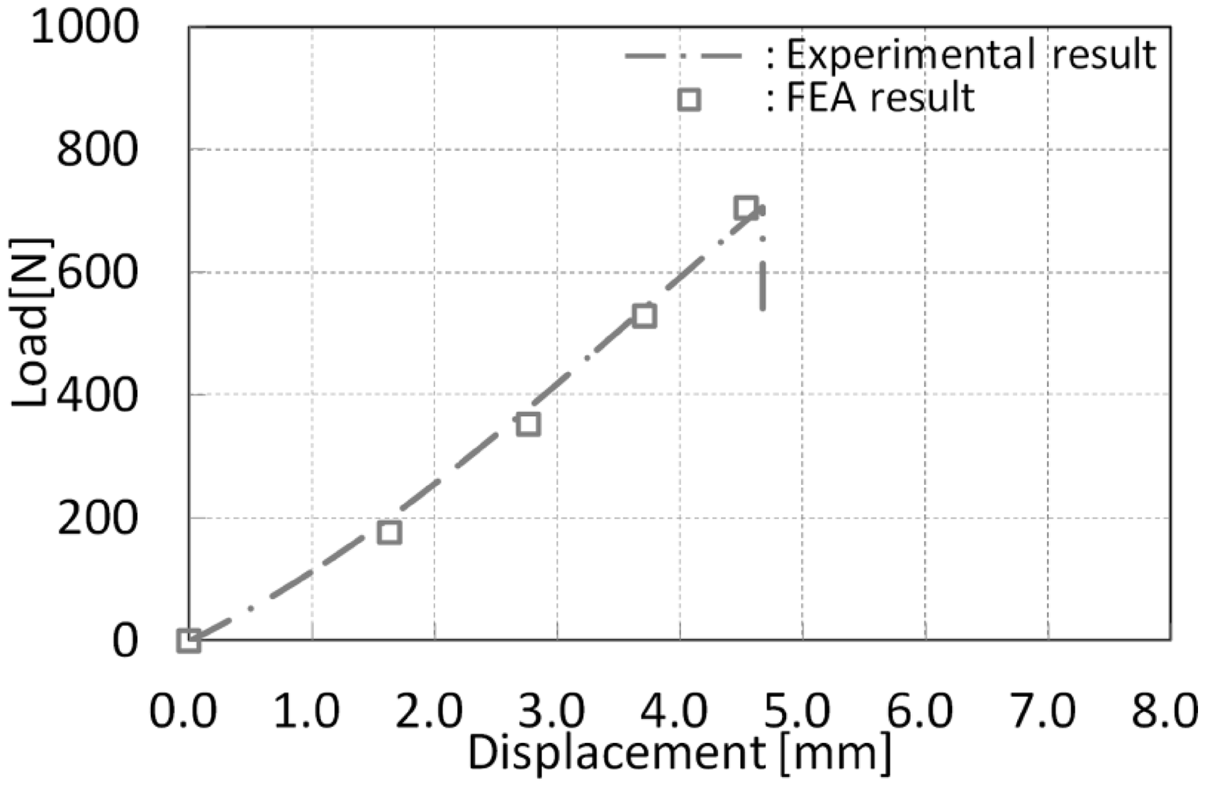
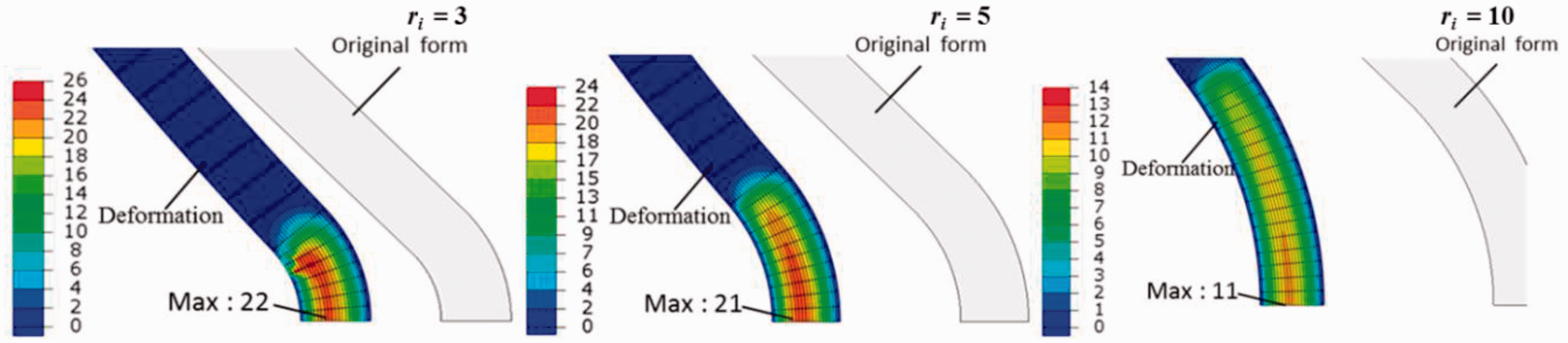
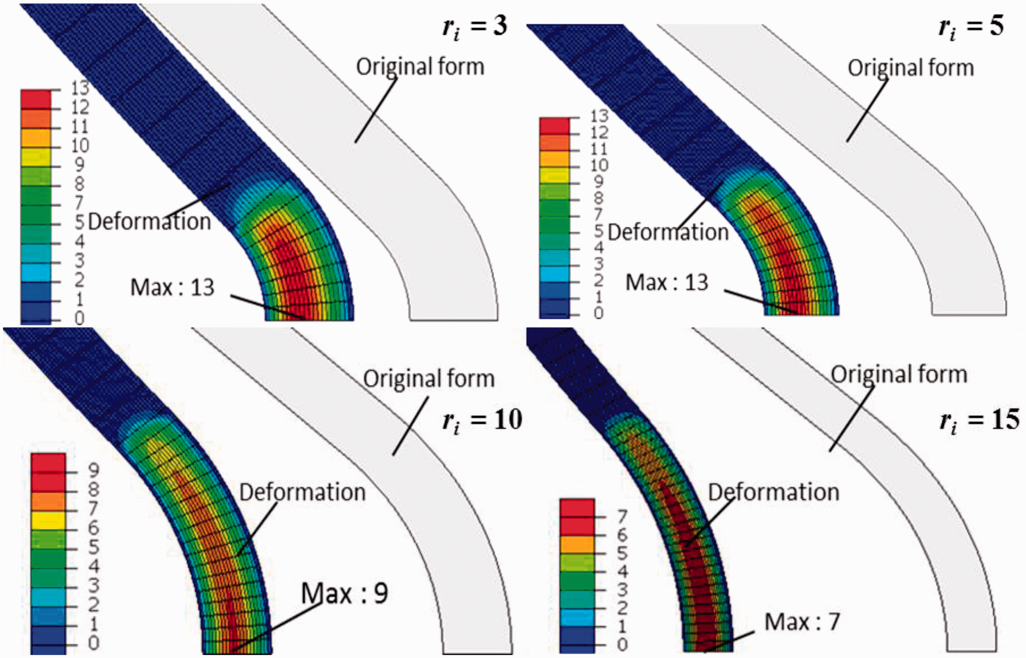
For the CMT specimens, the tangential stress distributions were illustrated in Figure 9. From the figure we found that both the maximum tangential stress and the minimum tangential stress, which indicated the maximum tensile stress on the inner side and the maximum compressive stress on the outer side of curved section in this research, increased with the increase of radius. In addition, for all the specimens in the same radius, the maximum tensile stress was higher than the maximum compressive stress. The radial stress distributions are illustrated in Figure 10. The radial stress was regarded to be the interlaminar tensile stress in this study. Contrary to the tangential stress distribution, the maximum radial stress decreased with the increase of radius. The radial stress distributions showed higher concentration at small radius. The specimen deformation imitated by the FEM also increased with the increase of radius.
The tangential stress (tensile/compressive stress) distributions of CMT specimens with different radii. The radial stress (interlaminar tensile stress) distributions of CMT specimens with different radii.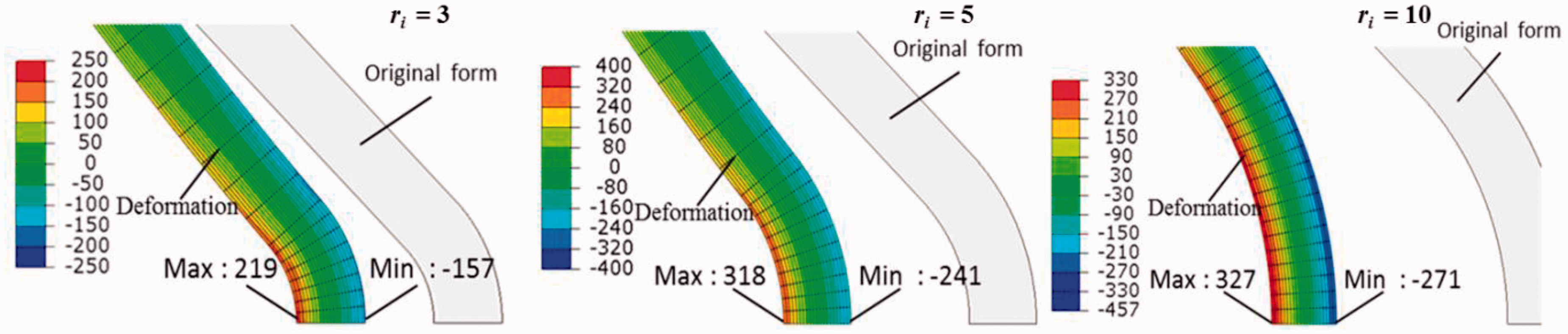
The tangential stress and the radial stress distributions of CTT specimens are illustrated in Figures 11 and 12. Same with the CMT specimens, both the maximum tangential stress and the minimum tangential stress increased with the increase of radius in CTT specimens; the maximum tensile stress was higher than the maximum compressive stress for the specimens in the same radius; the maximum radial stress decreased with the increase of radius and radial stress distributions showed higher concentration of small radius; also, the specimen deformation increased with the increase of radius. But despite the higher The tangential stress (tensile/compressive stress) distributions of CTT specimens with different radii. The radial stress (interlaminar tensile stress) distributions of CTT specimens with different radii.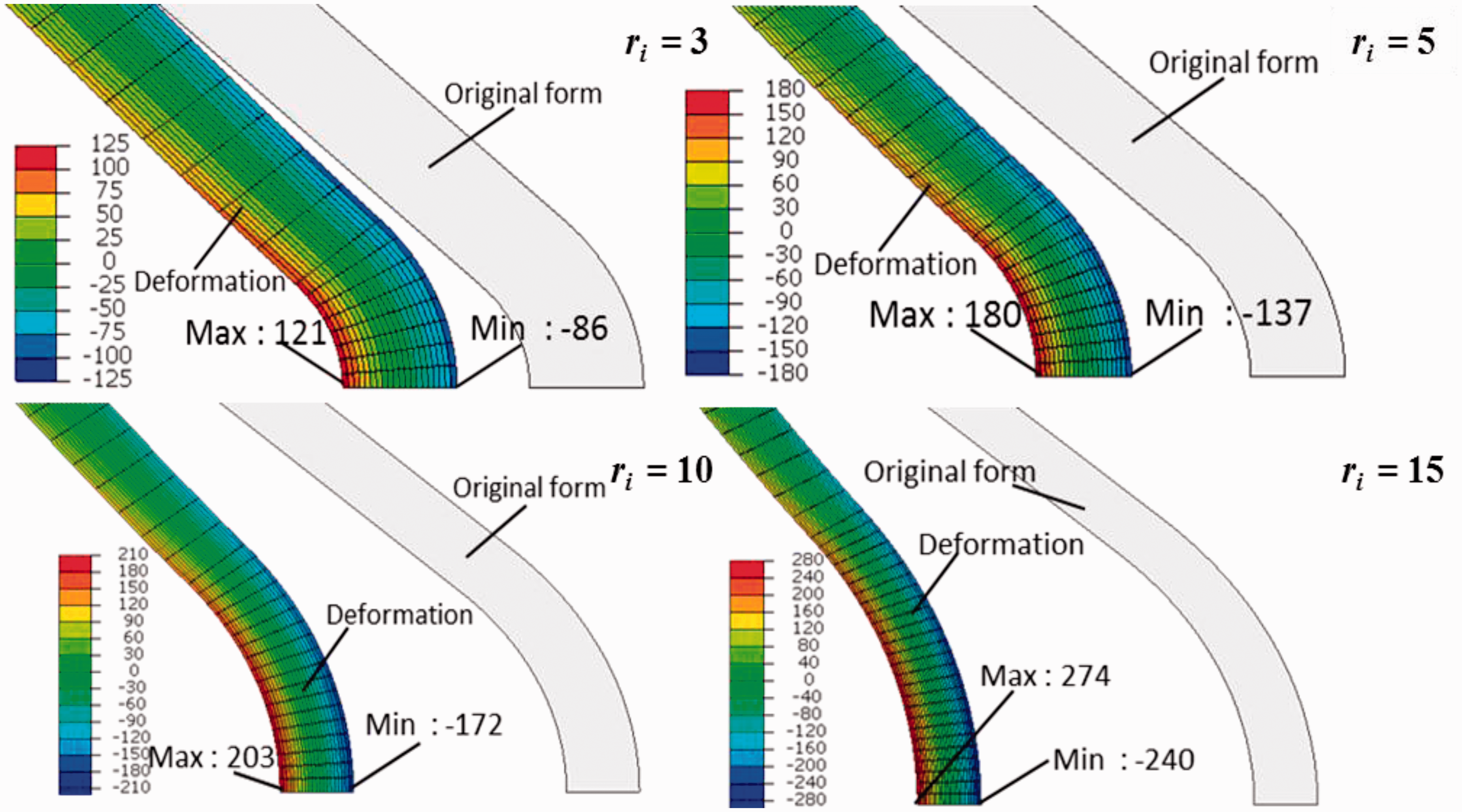
Discussions
The focus of our study was to evaluate the effects of curvature of the L-shaped specimens on the mechanical properties and the damage modes of SCFRTPs. To accomplish our objective, we conducted L-shaped tensile tests and finite-element analysis of two types of SCFRTP—the CMT and CTT. Considering the results given from the tensile tests and the FEM analysis, the geometric dimensions of the curved section demonstrated great effect on the mechanical properties and the damage modes of the specimens. In detail, the radius of the L-shaped specimens affects the stress distributions and the damage modes greatly.
The tensile tests in our study evaluated the effect of the radius change on the maximum loading force and damage modes of the specimens. The main trend we observed was that with the radius increasing, the maximum loading force was increased and the damage mode shifted from delamination to the fracture caused by tangential force (i.e. tensile fracture and compressive failure). Also the load–displacement curves demonstrated that the specimen stiffnesses with different radii were similar when the damage mode was same, and the stiffness decreased slightly when the damage mode shifted from delamination to tensile fracture and compressive failure.
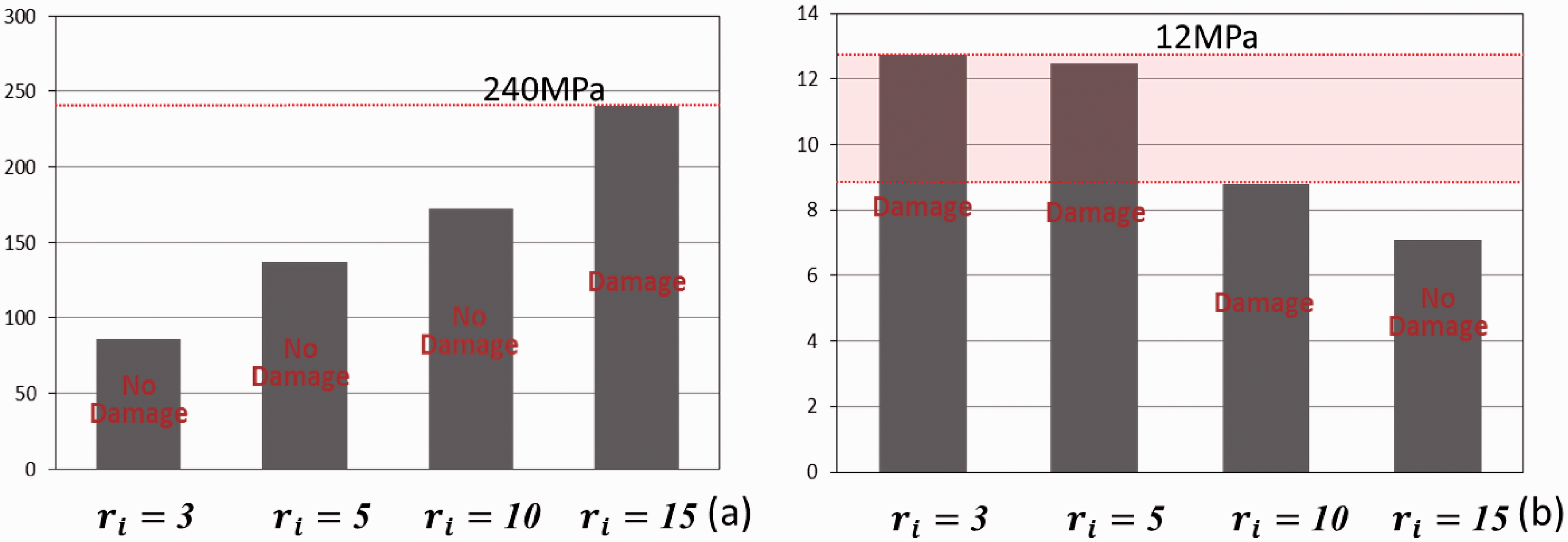
The FEM analysis in our research evaluated the stress distribution in the curved section of the specimens. From the results we found that the tangential stress (tensile stress and compressive stress) increased with the increase of specimen radius while the radial stress (interlaminar tensile stress) decreased with the increase of specimen radius. And the maximum tensile stress was higher than the maximum compressive stress in same specimen. Also, much higher interlaminar tensile stress concentration was found in small radius specimens. Under consideration of the results of the FEM and tensile test, we found that it is possible to extrapolate the strength of these materials. As the stress distribution shown in Figures 9–12 represents the stress state at failure, the strength of the materials can be extrapolated as the maximum stress accounted with the corresponded damage mode. In CMT specimens, as the specimens with Extrapolated tensile strength (a) and interlaminar tensile strength (b) of CMT. Extrapolated compressive strength (a) and interlaminar tensile strength (b) of CTT.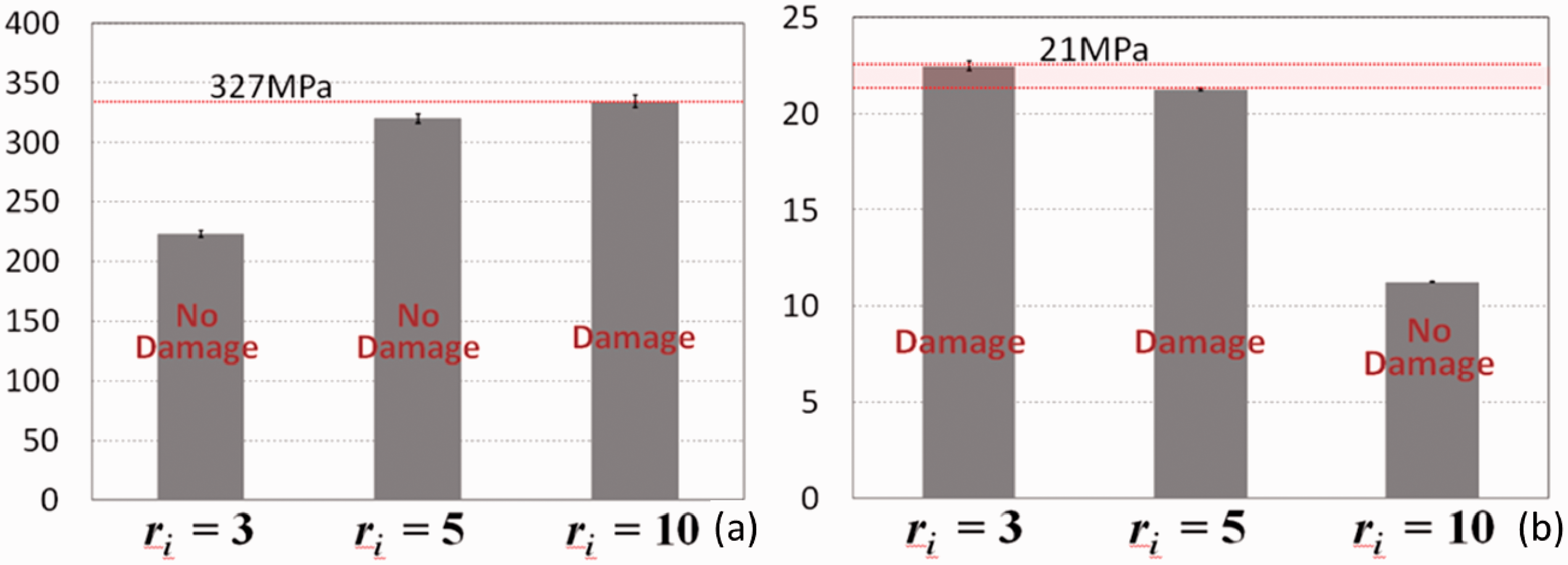
The results showed an abnormal phenomenon that despite the higher
The load–displacement curves given by tensile tests showed that the CMT specimens failed as brittle fracture, while CTT specimens failed as ductile fracture. We considered this difference as a consequence of the difference of the fibers’ residual stress generated during the molding process. Some researches indicated that the fiber flexural residual stress will generated during the compressive molding process of CF paper materials, and this residual stress behavior as the bending energy in fibers.38,39,43–45 Because the fibers in CMT are unimpregnated before the molding process, the interaction and the impregnation process between the fibers and the resin during the molding process will generate higher residual stress than the CTT composed with the pre-impregnated tapes. 45 We assume that the different fracture modes we observed in the tensile tests were effected by the bending energy stored in the curved fibers induced by the residual stress.
Both CMT and CTT materials have quite low interlaminar tensile strength compared with tensile/compressive strength because both CMT and CTT are fiber-in-plane oriented materials that contain the fibers mainly oriented in the principal plane. According to the rule of mixtures, the interlaminar tensile strength is surely much lower than the in-plane strength, because the interlaminar tensile strength is mostly provided by the matrix. Consequently, the stress concentration will lead to early delamination during the tensile test.
From the discussion above, radial stress concentration and delamination will occur during L-shaped tensile test when the radius of the specimen is small, and the interlaminar tensile strength can be extrapolated by FEM calculation. Therefore, this study can be regarded as an approach to determine the interlaminar tensile strength of fiber-in-plane oriented composites. However, in industrial applications, the difference of the in-plane and out-of-plane strength of the composites must be taken into consideration for mass-production vehicles: parts are designed with tensile or compressive strength to ensure the light-weight effect because these materials have much higher strength at in-plane direction. Otherwise, if the corner part is designed with tensile or compressive strength, the section will probably destruct at an unexpected lower load when its curvature radius is too small. The damage mode would shift from delamination to in-plane fractures (tensile/compressive fracture) with the increase of radius, as studied in this research. So the allowable radius of the composites for industrial applications needs to be decided to avoid the delamination. Accordingly, the allowable radius of CMT and CTT in this research will be
In conclusion, we evaluated the effects of different radii on the mechanical properties and the damage modes of CMT and CTT L-shaped specimens. The radius is key factor to determine the stress distribution and the damage modes of the specimens. Materials strengths were extrapolated according to the tensile tests and FEM results. The materials used in this study were aimed to be applied to the mass-production vehicles, so an allowable radius at curved section was given to each material to avoid delamination.
Additional work is underway to build a new FEM model with the consideration of plasticity and delamination progress. Additionally, structural strength of complex shape will be designed by FEM, and the methods to improve the interlaminar tensile strength through meso-structure will be taken into account.
Footnotes
Funding
This study was conducted as a part of the Japanese METI project “the Future Pioneering Projects/Innovative Structural Materials Project” since 2013fy. The authors would like to express sincere appreciation to the project members who have provided valuable information and useful discussions.